Thank you, Norm. Right now all knowledge is good knowledge.---Brian
You are using an out of date browser. It may not display this or other websites correctly.
You should upgrade or use an alternative browser.
You should upgrade or use an alternative browser.
Rockerblock I.C.--Something a little different-
- Thread starter Brian Rupnow
- Start date

Help Support Home Model Engine Machinist Forum:
This site may earn a commission from merchant affiliate
links, including eBay, Amazon, and others.
Barnbikes
Well-Known Member
- Joined
- Jul 19, 2014
- Messages
- 194
- Reaction score
- 41
Back when I was displaying hit and miss engines with my dad. There was a guy who would bring a throttle-governed engine and he ran it simply by putting a small brass tube connected to a 20lb tank in the carb opening and simply adjusted the valve on the tank till it ran the way he liked.
Barnbikes--I know that can be done, but if possible I want to do it the "right way". I'm not sure exactly what the "right way" is, but by the time I'm finished, I will.---Brian
Brian,
Have you looked at F.A.M.E. Tips and Links? The third tip is by Richard Williams (the designer of the demand valve that you have). He shows a picture of the regulator directly on the gas bottle, a short length of hose to the demand valve and then the hose to his engine. No sign of a pressure gauge!
http://www.floridaame.org/
Dave
The Emerald Isle
Dave, I have seen that. I've almost worn the internet out looking for information about running small engines on propane. I won't be real clear about it until the regulator I ordered shows up here and I see if it can be mounted directly to a propane bottle.---Brian
After a lot of reading and research, I have found out the following. Normal outdoor gas barbeques run on approximately 11" of water column propane pressure. 14" of water column equals 1 psi. The instructions in the "kit" I purchased from Jerry Howell recommends 1 to 3 psi pressure. I just took a tour thru my local Walmart (shudder) and found that they have a regulator intended to run an outdoor barbeque. This regulator screws right onto a propane tank and has a 16" long flexible high pressure line that runs from the regulator to the barbeque. It does have a gauge on it but the gauge doesn't have any numbers on it, just "low" medium" and "high". This unit retails for $26 and would probably be good enough for what I am doing. I have seen posts where this is what was used in conjunction with a "gas demand valve" to run small model engines. I don't believe the regulator was pressure adjustable, but there was a valve on it which closed off flow from the tank, so it would be to some extent "flow regulated" which is not what I want. My instructions in the "kit" seem to recommend using 1/8" bore silicone tubing between the regulator and the demand valve, and between the demand valve and the engine. It also seems that the "demand valve" is of particular use on throttled engines. the engine vacuum is what pulls open the "demand valve" and lets propane flow to the engine. As you increase the throttled speed, this makes the engine vacuum increase, ( this is exactly opposite to what I know--if you ever drove a car with vacuum operated windshield wipers, you would know that when you stepped on the gas to speed up and pass another car in the rain, then the engine vacuum would drop and the damned wipers would quit just when you needed them the most.) which allows more propane to flow to the engine as it is revved higher. If the engine for some reason stalls out or quits, there is no vacuum, so no propane will flow.

$24.99
$27.99
HOZLY 5PCS/Lot ISO30 Tool Holder Clamp Flame Proof Rubber Claw CNC Machines Automatic Tool Changer
HOZLY

$99.99
AHS Outdoor Wood Boiler Yearly Maintenance Kit with Water Treatment - ProTech 300 & Test Kit
Alternative Heating & Supplies

$24.99
$34.99
Bowl Sander Tool Kit w/Dual Bearing Head & Hardwood Handle | 42PC Wood Sander Set | 2" Hook & Loop Sanding Disc Sandpaper Assortment | 1/4" Mandrel Bowl Sander for Woodturning | Wood Lathe Tools
Peachtree Woodworking Supply Inc

$94.99
$109.99
AHS Woodmaster 4400 Maintenance Kit for Outdoor Wood Boiler Treatment
Alternative Heating & Supplies

$39.99
$49.99
Sunnytech Low Temperature Stirling Engine Motor Steam Heat Education Model Toy Kit For mechanical skills (LT001)
stirlingtechonline

$12.56
$39.95
Complete Plans for Building Horse Barns Big and Small(3rd Edition)
ThriftBooks-Atlanta

$40.02
$49.99
Becker CAD 12 3D - professional CAD software for 2D + 3D design and modelling - for 3 PCs - 100% compatible with AutoCAD
momox Shop

$45.99
Sunnytech Mini Hot Air Stirling Engine Motor Model Educational Toy Kits Electricity HA001
stirlingtechonline

$89.99
Outdoor Wood Boiler Water Treatment Rust Inhibitor- AmTech 300 & Test Kit
Alternative Heating & Supplies

$519.19
$699.00
FoxAlien Masuter Pro CNC Router Machine, Upgraded 3-Axis Engraving All-Metal Milling Machine for Wood Acrylic MDF Nylon Carving Cutting
FoxAlien Official
![DreamPlan Home Design and Landscaping Software Free for Windows [PC Download]](https://m.media-amazon.com/images/I/51kvZH2dVLL._SL500_.jpg)
$0.00
DreamPlan Home Design and Landscaping Software Free for Windows [PC Download]
Amazon.com Services LLC
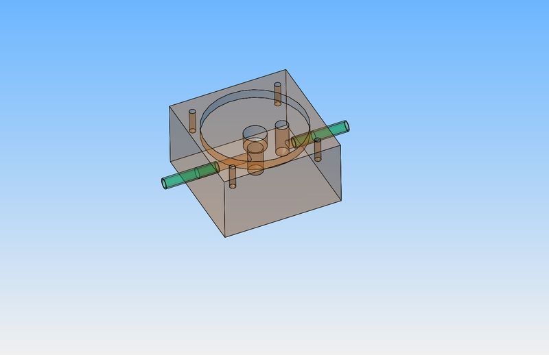
I just found out that my "real work" schedule has been shifted this week and I don't have to go in tomorrow. so---without giving away anybody's "proprietary" drawings, I think I will work on the gas demand valve tomorrow. The block of aluminum is 1 3/4" square x 1" thick. The brass inlet and outlet tubes are 4 mm o.d. x 1/8" i.d. x 0.8" log, and are Loctited into place.


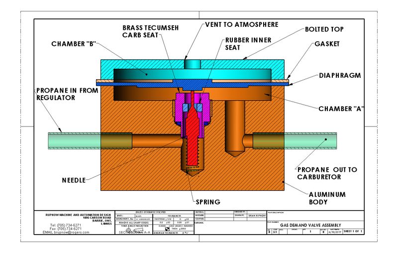
Okay--Let's see if I can get this right. Gas from the regulator flows to the left hand side marked "propane in from regulator". Propane can not get past the closed red needle valve which is firmly held against the "rubber inner seat" by the spring. Then you try and start the engine, and the engine creates a vacuum that sucks on the port marked "Propane out to carburetor". This suction pulls the diaphragm down, which acts on the top end of the red "needle" and forces it down away from the "rubber inner seat" in the "brass Tecumseh carb seat". As soon as the "needle" is pushed away from the "rubber seat" the Propane begins to flow thru this newly created path into chamber "A" and then out to the carburetor. As long as there is any suction from the engine, propane will flow to the carburetor. As soon as the engine piston is past the intake stroke and beginning to go up on the compression stroke, the vacuum from the engine stops and the "spring" closes the red "needle" into the "rubber inner seat" and the propane stops flowing until the cycle repeats itself.--THIS POST HAS BEEN EDITED--I HAD IT BACKWARDS THE FIRST TIME


Hello Brian, You have everything correct. With propane and its very high pressure in the container, it is imperative to control that pressure safely. So the reason for the regulator to be connected to the container. When that pressure has been safely controlled, it is a piece of cake to control the low pressure safely. Norm
Norm--I feel a bit like the magician did, the first time he sawed a woman in half.--Jeez, I hope this comes out right-----
The reason I am stumbling around a bit on this propane business is that A--I have never built one before, and B--the owner of the outfit that now sells Jerry Howells plans is a complete LaLa and knows absolutely nothing about the plans he is selling. I contacted him for technical advice about how everything goes together, as there is no assembly drawing with the "kit". His response was that he had no idea, he was not a technical person, and that although he now has the rights to Jerry Howells stuff, he doesn't have a clue how it works himself. He suggested that "Anybody who can build an engine can probably figure it out without much problem."
BaronJ
Grumpy Old Git.
Hi Brian,
I don't post much but follow your work with some awe. Re the demand valve, it might be instructive to get hold of an old washing machine water valve and take it apart.
HTH
I don't post much but follow your work with some awe. Re the demand valve, it might be instructive to get hold of an old washing machine water valve and take it apart.
HTH
ICEpeter
Well-Known Member
Hello Brian,
If I am not mistaken, the person you talked to is the son of Jerry Howell who inherited / took over Jerry's business after Jerry's passing. I might be wrong but that was my understanding after the change in Jerry's website some time ago.
Peter J.
If I am not mistaken, the person you talked to is the son of Jerry Howell who inherited / took over Jerry's business after Jerry's passing. I might be wrong but that was my understanding after the change in Jerry's website some time ago.
Peter J.
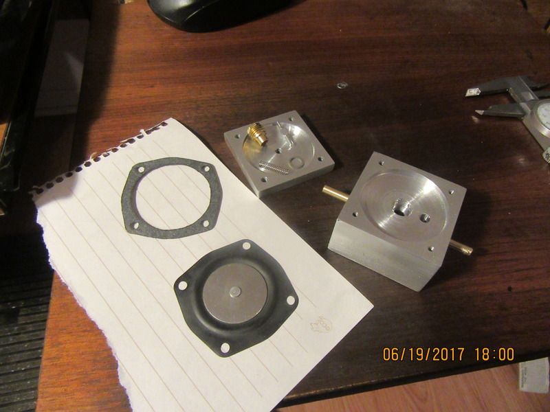
Today I made the main body, the bolt on "top" and the inlet and outlet tubes. This picture shows the components I made, along with the purchased components. I have to assemble it and make sure it works the way I think it should. I will let you know tomorrow. The test I envision is crude but should work. Good wife will be the propane tank and blow into the tube which will eventually be connected to the propane tank. I will be the engine, and suck on the other tube. Wife shouldn't be able to blow any air unless I provide some vacuum on the other tube. I just hope good wife doesn't find out I compared her to a propane tank on the internet.!!


Hah---I didn't have to enlist good wifes help after all. I can suck on the engine side, and get air. The only way the air can get to me is by coming thru the tube which will be attached to the propane bottle. I can not blow thru the tube which goes to the propane bottle which means that the needle valve is sealing unless there is some vacuum on the engine side. I did have to put the gasket on the other side of the diaphragm from where I show it in my drawing. When it is arranged as I show it in my diagram the diaphragm puts enough pre-load on the end of the needle valve to keep it from closing all the way and lets it bleed air. I am rather impressed with the way this valve works. Of course I won't know for certain until the regulator I have ordered gets here, but so far, so good.
A common theme that I am seeing in all of the research on running a small i.c. engine on propane is that the fuel discharge orifice in the carburetor must be enlarged by about 50% and that the air intake diameter should be reduced by gluing in a bushing. (This creates more "suction at the "gas demand valve"). Of course the trick seems to be in knowing just how much to reduce the air inlet. Best suggestion is to put a piece of tape over the air inlet opening and poke a hole in it, starting with a small hole and then enlarging it in stages, trying the engine to see how well it runs after each "hole size adjustment". The line which feeds propane to the carburetor hooks up to the same port on the carburetor that the gasoline line originally hooked up to. It also seems that the needle valve must be opened more than when running conventional gasoline. I still haven't totally bought into the fact that when the throttle is opened on the carburetor that it will create more vacuum and thus flow more propane into the carburetor. In my experience, opening the throttle on any gas engine makes the vacuum fall off rather than increasing. The "gas demand valve" which I built yesterday serves only to shut the flow of propane off if the engine should quit.
The piston moving towards bottom dead center creates a vacuum, which causes air to rush in thru the carburetor air intake. The air rushing in thru a restricted area in the air intake creates a low pressure area at the venturi. This resultant low pressure area is what sucks the liquid fuel up from the fuel tank. Okay, I knew that. If you restrict the opening of the air intake, then the air has to flow faster thru the restricted area to fill the volume of the cylinder. The fact that the air has to move faster, probably increases the "venturi effect". This gets into theory that I'm not really sure about. If that theory is correct, then restricting the air intake probably does increase the vacuum due to "venturi effect" and give a stronger signal to the "gas demand valve", thus letting more propane flow. I got an email from the Canadian company that reps for "Coilhose" telling me that my regulator and gauge had arrived in Ontario. Originally I was going to drive to Toronto and pick it up, but my life has been so busy this past week that I didn't have a chance to. I have ask them to send it to Barrie by courier, so hopefully I will have it this coming week.---Brian
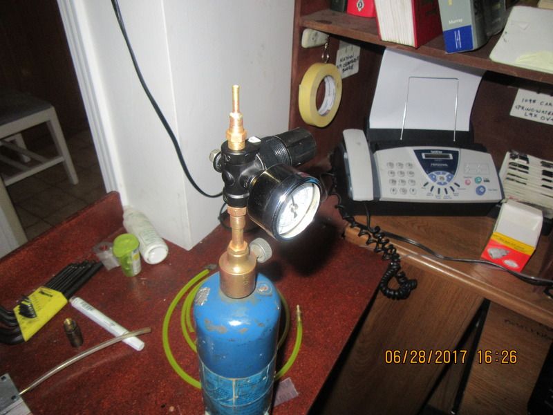
My regulator and gauge arrived, and as I suspected, they don't have any way to hook up to a propane bottle. This is the gauge and regulator recommended in the Jerry Howell "propane demand valve" kit. However, I resorted to "do it myselfry" and worked with an empty propane torch and nozzle to make what I needed. The torch already has a shut off valve which I could use. The gauge screws into one port on the regulator. I hunted around in my box of fittings and found 3 other brass fittings that had the correct threads, and silver soldered the ends I needed onto them. I haven't leak tested anything yet, but it looks good.


That pressure gauge is 0 to 60 psi. Am I impressed? No, not really. I am flying semi blind on this entire Propane thing. The information in the "kit" from Jerry Howell is not up to my expectations. As I understand things so far, the engine should operate on about 1 psi. However--I suppose that Propane is a gas, the same basic nature as air, and the gauge and the regulator probably won't know the difference. If I don't blow myself up in the process, I am going to fight this thru to a running engine. So far, I'm out $81 for the regulator and gauge. If it all doesn't work as I had hoped, I can still buy a tank of Propane with a "fixed value" regulator to run campstoves at Walmart for $26.---Brian
Similar threads
- Replies
- 302
- Views
- 71K
- Replies
- 212
- Views
- 80K
- Replies
- 22
- Views
- 9K


