Potty Over Crank Wall Engine

Home Model Engine Machinist Forum

Help Support Home Model Engine Machinist Forum:

This site may earn a commission from merchant affiliate links, including eBay, Amazon, and others.

SBWHART

Project of the Month Winner!!!
Project of the Month Winner
Joined
Jan 17, 2009
Messages
887
Reaction score
82
Started to cut metal for this engine: for those of you who didn't pick it up her's my thread on the design

http://madmodder.net/index.php?topic=3990.0

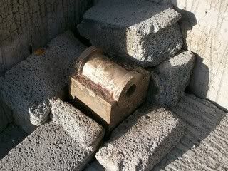
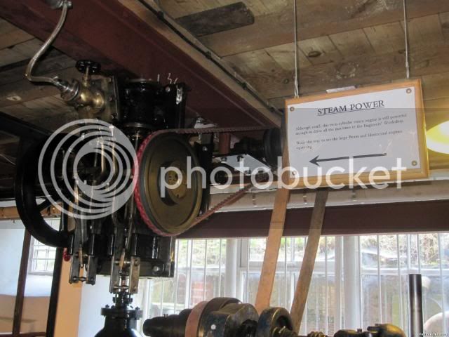
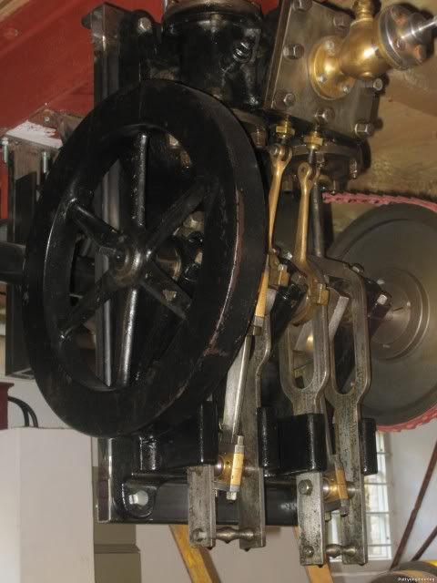
And a pic of the engine the model will be based on.
IMG_0178-1.jpg


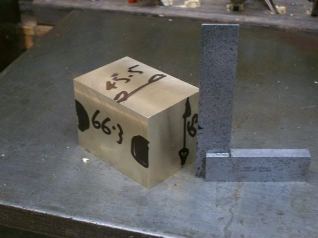
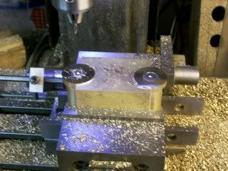
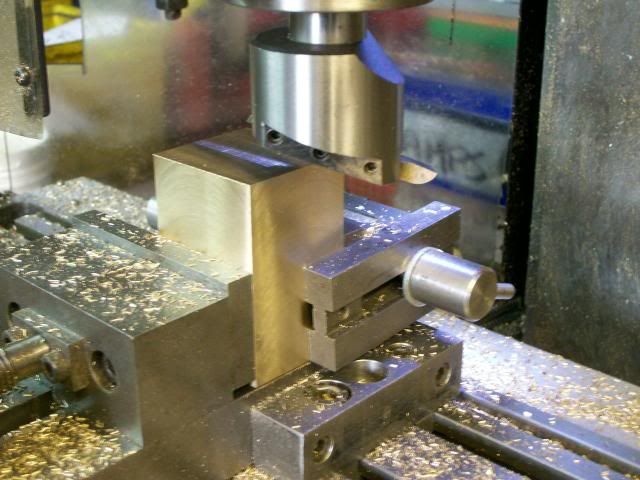
Using a chunk of brass donated by John:- thanks John :) first square it up and bring it to size with a fly cutter.
100_4512.jpg


100_4515.jpg


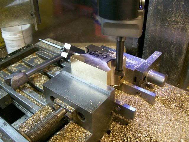
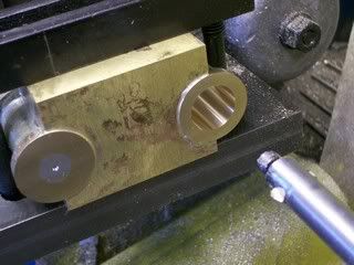
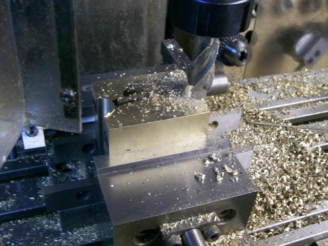
Then with a 18mm end mill cut a couple of scallops down the sides,
100_4518.jpg


Then set the boring bar up to cut a 12.5 mm rad

100_4519.jpg


Open the scallops out to 12.5 mm rad

100_4525.jpg


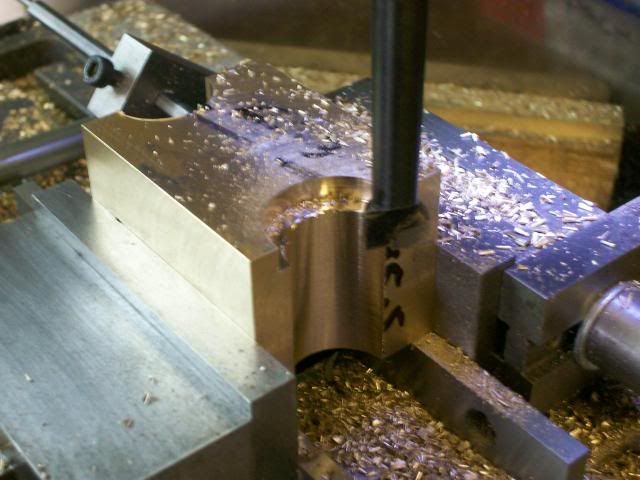
And counter bore them out to 15 mm rad
100_4526.jpg


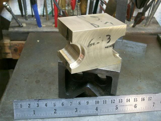
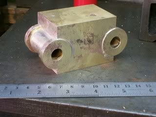
so you've got this

100_4529.jpg


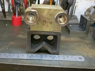
Then turn up a couple of brass spools that fit into the scallops
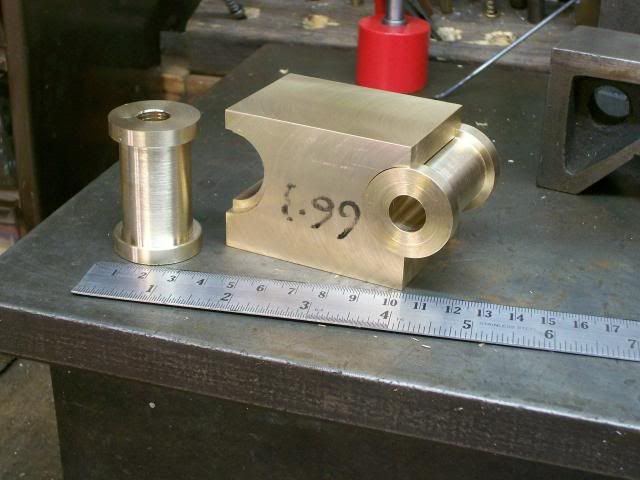
100_4535.jpg


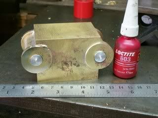
And you've got your self a twin cylinder.
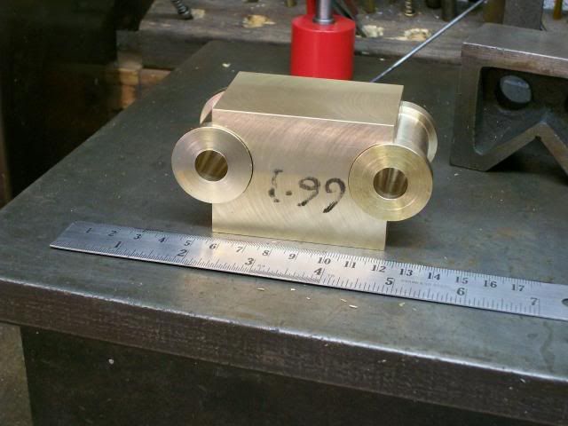
100_4534.jpg


Well you will have when you've silver soldered them together thats a job for the week end :- if I can sneak away, our son and wife are staying with our new baby granddaughter, so we will have a string of visitors ho-ing and ar-ing, and doesn't she look like youing.

:D :D :D :D :D :D

Really looking forward to it

Stew
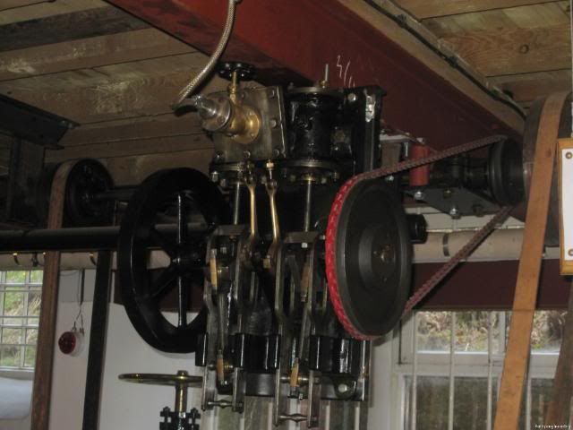
 
Is the 1st picture upside down ? Or are you from the Land of Oz ? :big:
 
Off to a flying start Stew, I'll be watching with interest.
 
ChooChooMike said:
Is the 1st picture upside down ? Or are you from the Land of Oz ? :big:

Nope

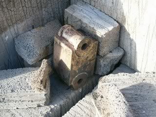
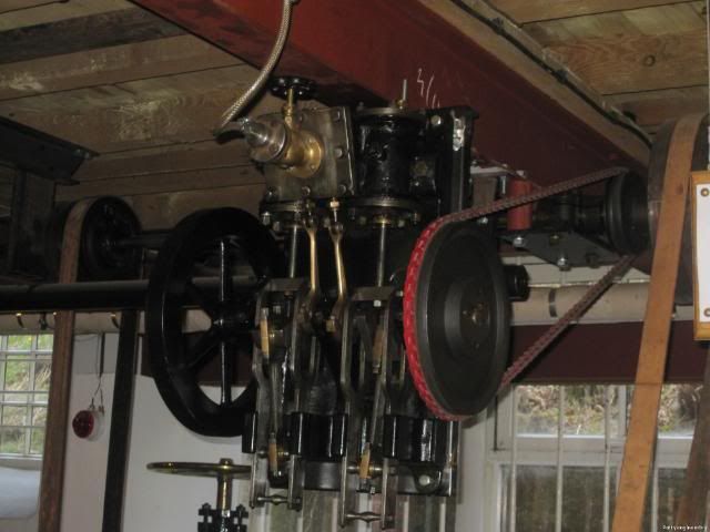
The engine was slung under a beam, here's a better pic. They were usually fixed to the wall of the work shop.

IMG_0179.jpg


Stew

 
After a hectic few days I needed a bit of r and r in the shed, but it was really great having all the family together. :D

Made a start on soldering the bits for the cylinder together, for those of you who missed it in my loco boiler thread this is the kit a I used to solder.

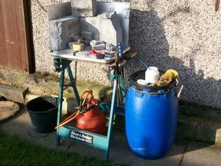
I hearth cobbled together from an old ally baking tray, thermalite blocks from B and Q, a propane burner with a large nozzle fitted a bucket of water for quenching, some easy flo solder and tenacity flux, the barrel is just there to keep everything at a handy height.

100_4539.jpg


I solder one cylinder at a time building a little wall around it to keep the heat in.

100_4536.jpg


Both ends done I just opened up the wall so that it would cool quicker after five minutes I quenched it in the water and put it in the acid pickle for 1/2 hr.

100_4537.jpg


This it it all soldered up

100_4541.jpg


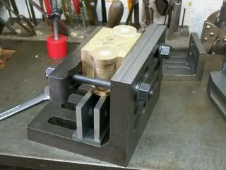
Then I just cleaned one end up with a fly cutter, the other end I plugged the bores with some nuggets of ally secured with loctite

100_4542.jpg


Set it back up in the mill and cleaned them all up again with the fly cutter, they picked the datum edges found the position for the cylinder centre line and centre drilled into the nuggets.

100_4543.jpg


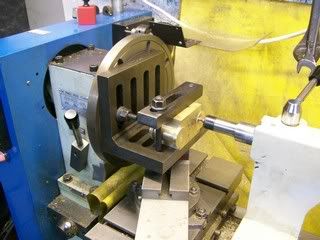
To machine the bores I'm going to set the cylinders up in an angle plate on the lathe face plate.

So first job clamp the cylinder up nice and square in the angle plate, I won't slacked the clamp bolts until both cylinders are bored this will ensure that cylinders are parallel.

100_4545.jpg


Remove the parallels and clamp the angle plate to the face plate, I'm just using the centre to help hold thing in place and roughly get position. (its one of those jobs you wish you had three hands) just tighten the clamps lightly

100_4546.jpg


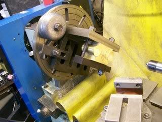
Add counter balance weights I've found the best way to check the balance is to disconnect the head stock from the drive remove the belt or disengage the gear which ever way your machine work, and give the face place a spin with your hand, what your after is for it to come to rest in a radome position if it stop in the same place move the weight or add more weight until you get it balanced.

100_4547.jpg


Using a wobble bar between the centered nugget and a running centre clock the bar up tap the angle plate until it running true, and you've got the cylinder positioned, tighten all the clamps.

100_4549.jpg


Now face plate work is probably the most hazardous job you can do on a lathe bits can fly off and do a you a real nasty, so make sure everything is nice and tight and can't come adrift, before you switch the power on, turn the lathe over by hand making sure nothing can catch, and check that you've got the speed set on slow, and stand to one side when you switch it on just in case.

OK everything nice and safe stick a drill down the bore to get rid of the ally nugget. and bore to size

100_4550.jpg


Thats the first bore done the R and R for tomorrow is the second bore to do that just move the angle plate over clock position up with a wobble bar and bore it out, the cylinders will come out perfectly parallel.

Stew


Got right down to doing number 2 bore this morning just a mater of repositioning the angle plate on the face plate and clocking up on the centre.

100_4556.jpg


And boring it out, I like to sneak up onto the size taking smaller cuts as I get closer and run the final cut through a couple of times to take the spring out of the bar, I don't worry too much about getting exact size as long as its within 0.1mm I'm happy Its far easier to make the pistons to fit.

Her we have them both done

100_4560.jpg


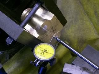
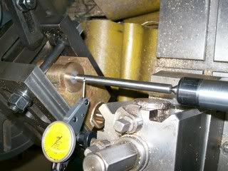
Then over to the mill I left it set up with the stops so it should locate close to where I left it but decided to check bore position before I started the next op using a coaxial indicator.

100_4565.jpg


It was went back within 0.2 so got it back on zero then first centre drill followed M2.5 tapping drill for the cylinder covers, be careful you don't end up with a hole where the air gallery will go, I did this on my first engine a built a few years back, you live and learn.

100_4566.jpg


Tap M2.5 using the tapping stand to get everything nice and square.

100_4570.jpg


Then drill and tap M5 on the underside to take the feet.

100_4567.jpg


As it would make the cylinder a difficult shape to hold I left angling the valve port face till last.
I just angle the cylinder block 15 deg in the vice and milled off the meat.

100_4573.jpg


At this point I was gasping for a cuppa so decided to leave milling the valve ports until tomorrow when I'll be fresh.

Stew
 
Thanks Pat

My lathe is a 3 in 1 so its got a huge swing for its size so I can get a set up like that in the space, I removed the mill drill when i got my mill, doing it in the lathe gives you the power feed which helps getting a good finish, most mills don't have verticle power feed.

The method is used a lot for twin inside loco cylinders It's how I machined the cylinders for my loco.

Cheers

Stew
 
It's getting along nice, Stew. Thanks for the pics and words.
I like your sign; Our Father.. Who Art in His Shed.
Sounds like your family knows you well!
 
Thanks Dean

The sign was a birthday card from our son, couldn't resist the temptation of hanging it up.

:big:

Stew
 

Thanks for the interest Guys

Milling the valve ports:- this is what I call a **** or bust job its easy to get things wrong then your in it deep.

So I like to mark the ports out this doesn't have to be dead accurate you'r just using this as a guide so that you get the wide port in the middle and the narrow ones at the ends and that the spacing is about right, I also like to make myself a crib sheet showing the cordinates I'm going to use.

I work from the centre of the valve face so first thing is find the centre and zero up the DRO in the x and y.

100_4576.jpg


The middle port is 5 mm wide and the outer are 3.5 mm

Index to the correct cordinate:- centre drill and drill to depth using a number drill, thats just smaller than the slot drill, this stops the slot drill pulling into the corner and giving the port a hockey stick end.

100_4580.jpg


Then using slot drill mill out the ports, as the valve face is angled each port is milled to a diverent depth, I took them considerable deeper than I planned on the drawing but with the actual job in my hand I had a brain wave on how to connect the ports up something that troubled me when I did the drawing as I was unsure how to do it.

100_4587.jpg


Now the brain wave was :smart: drill into the ports from the side, and drill through from the top of the bore to join it up, screw and plug the inlet ports to seal them up, the exhaust is left open.

Finding where to start the drill to join up with the ports.

100_4589.jpg


Drilling through into the ports.

100_4590.jpg


Lining up the cylinder to join the inlet port from the cylinder.

100_4592.jpg


Joining the inlet port up.

100_4593.jpg


And her we have the ports drilled

100_4596.jpg


100_4598.jpg


I'll amend the drawing to reflect this change.

I'll put the cylinder to one side now as I want to make the valve chest and use it to mark of the fixing holes in the cylinder. But before I can do that I've got a huge tidying up job to do in the shop, I'm very much from the:- take it out, use it, put it down school of working as a result I end up with tools and bits of kit spread all round the shop.


Stew
 
Made a start on fabricating the steam chest, the parts are straight forward machining.

100_4599.jpg


The dowels well keep everything in place when soldering, there not a particularly tight fit and I filed a flat on them to let any gas escape as the job heats up other wise the pressure will pop them out.

This is how I set it up for solder, with the joint fluxed and rings of solder round the glands and little nuggets of solder sitting on the joint, putting it in the corner helps keeps bits in place and retain the heat, I tuch on the end of the dowels with a filler rod just to fill them in.

100_4601.jpg


This is it after 5 minutes in the acid i stuck it back in for an hour

100_4604.jpg


Cleaned the outside up with a file then milled the faces flat so they will make a good seal.

100_4605.jpg


Then with it upright in the vice find the centres and drill and tap the sealing gland.

100_4606.jpg


Starting to look like a cylinder now.

100_4610.jpg


Stew
 
Off to a great start Stew. Your fabrication methods seem to be very similar to my own, tho I usually only use short bits of 1/16" brazing rod (manganese bronze) for the 'dowels'.
 
Thanks for the comments guys.

Tel:- never tought of brazing rods I have some that I could have used, I had to turn down some 5mm brass to 3mm to make the dowels, the rods would have been much better, I'll file that one away.

Pat:- thats more or less what I did I flattend the ends a bit to give them a bit of grip. I have had pins push out due to gas expansion and spoil a job in the past, I was edging my bets.

Stew
 

I had to change the layout of the holes in the steam chest, when I came to try the chest on the cylinder to see how thing looked I realized that changing the air feed hole position meant that I would break through into them with the steam chest fixing holes, not as though it would have been a disaster as the studs will be sealed in and the chest will be sealed on the cylinder but I thought it best to avoid it.

So with the new layout marked on the chest first drill them 3mm

100_4615.jpg


When I milled the steam ports and machined the chest I marked the center line with a tiny dimple from the centre drill, this is so I will have a mark to line things up. So with two way sticky type on the chest stick it to the cylinder centrally and square using the marks and the back edge of the chest lined up on the back edge of the cylinder, then with a little transfer punch made from a bit of 3mm silver steel (drill rod) mark the position of the holes in the cylinder.

100_4616.jpg


Set the cylnder level using the digi level, a real handy bit of kit , carefully line up on the marks with a centre drill and then drill M3 tapping.

100_4619.jpg


100_4621.jpg


Then on the tapping stand and the cylinder jacked level using a sine bar tap the holes nice and square.

100_4626.jpg


Now for the cover a bit of 2mm brass plate was rough cut out and the chest placed on top and a line scribed round it.

Mill to the line, the parallels are to reduce the angle of dangle and give it a bit of extra support.

100_4627.jpg


Then clamp the chest to it and drill through when you've done the first hole put a clamp bolt through it do the second and put another clamp bolt through it as well, remove the clamp and drill the rest of the holes, I used a number 31 drill to give a little wiggle room.

100_4629.jpg


100_4631.jpg


The hole in the middle will take the air intake flange the top of this flange will be leveled off so the hole in the cover needs to go in at an angle, so with the cover bolted to the chest and set up at 15 deg, first a big centre drill followed by a slot drill this angle the hole nicely.

100_4632.jpg


This is the cylinder assembly so far

100_4634.jpg

 
Always a fascinating thread from you Stew.
That is really looking good.
 
Thanks Zee your interest is much apreciated.


Stew
 
I'll be the first to admit I'm not sure what's going on here, but i'm mighty impressed with the workmanship. Looks like he cylinders are at an angle to the valve chest?

Chuck
 
Thanks Pat/Chuck

Chuck

Yes the valve chest is angled to the cylinders, you can see that here in the picture of the original.

IMG_0179.jpg


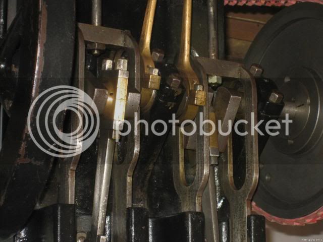
When I first saw the engine in the museum, it was the feature that first caught my attention, then I noticed the over crank arrangement, and thought it would be a good subject for an engine build.

I couldn't find any details about the maker of the engine, and when I contacted the museum all they told me was what I knew already. Its not a very big engine about 3 ft * 3 ft with a 2 ft ish fly wheel. I figure these sort off small engines were made in their hundreds if not thousands to power small work shops, mounted up on a wall driving line shafting they didn't take up much floor space.

Hers a few more pics of the original

IMG_0176.jpg


IMG_0189.jpg


IMG_0179.jpg


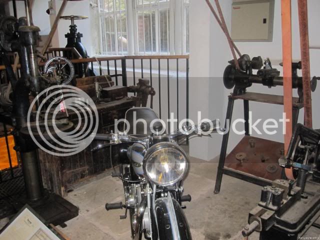
It was being run on air to drive a these machines with line shafting.

IMG_0173.jpg


My only criticism was the brammer belting the victorians would have used leather.

Thanks again for your interest.

Strew
 
Pat J said:
I would call that sort of a suitcase engine, like those used in the Volkswagon stationwagons, and about the size of a large suitcase.

Quite an interesting and compact engine.
It was the electric motor of the 1800's (but more fun than an electric motor).

Pat J

Thats a good description ;D

When I started my apprenticeship the factory still had one production line of small presses driven by line shafting the power source in this case was an electric motor a few years later they bought one machine that did away with the whole production line, and the shafting was torn out.

Stew
 

Ever had one of those days when you think you should have stayed in bed.

Putting the pipe coupling on the steam chest cover I turned the bit up, and soldered it to the cover, this is the set up I used to solder it, coupling sitting on a flat surface cover angled bit of heat onto the mill to clean the top of square and drill the stud holes.

100_4635.jpg


This is what I ended up with.

100_4640.jpg


You can see that the darn thing has slipped and I've ended up with quite a taper on the flange

Strike 1 over to plan B

Cut it off and clean the solder off and start again this time I thought it would be more stable if I milled an angle on the coupling

100_4641.jpg


Line it up on the cover and solder it on, square it up drill holes. Nope the double darn thing had moved also and looked like the leaning tower of thingy.

Strike 2 over to plan C

No more piddling about and stop trying to be cleaver just solder a lump of brass on the cover mill the top off square and drill the holes.

100_4644.jpg


That sorted it :thumbup: :D

Stew
 

Latest posts

Back
Top