'Poppin' Flame Licker Engine

Home Model Engine Machinist Forum

Help Support Home Model Engine Machinist Forum:

This site may earn a commission from merchant affiliate links, including eBay, Amazon, and others.
Nick,

Almost anything can be repaired, it all depends on how much time you are willing to spend on doing it compared to the price of a new vice. For my own repairs, I work on about £10 per hour. So if it is going to take me 6 hours to repair, that would be £60. In that case I would go out and buy a new one, as they are around that price anyway. I use a slightly less figure of £5 for making tooling. If it costs me more in time costs to make than buying a new one, then I buy it. I find that system works very well for me as my shop time is now very precious to me.

Now regarding your milling to a line. If your layout is done accurately and with fine scribe lines, and you can 'split the line' with your cut, you should be well within 0.002" (0.05mm) of required size. At one time, that was how most machining was carried out when you couldn't get some sort of measuring instrument in there.
For cutting a slot to a required size, say 1/2", it is always preferable to cut it with a one size down cutter first 7/16" or 15/32", using the centre line of the slot, then follow up with the correct size afterwards, otherwise you might find your slots turning out too wide if you used the 1/2" one first.

John
 
Kel,

Yes I may need to utilise the clamp set. I did consider milling it upright but I'd have to leave square corners then as have no ball end mills. Suppose the only consolation is that I didn't buy the vice, it was a freebee.

John, yes you are probably right. It's the same reason I haven't made a quick change tool post. I've found a 4" vertex K4 from Warco for £62 incl delivery and vat which seems about the best price. Arc euro have tool makers vices for a good price, not quite as quick to open and close but they open further, have deeper jaws for a few more quid, then there are those quick release types which are about half the cost - not quite sure which to go for to be honest!

Thanks for the advice on 'splitting the line' and cutting slots. With my crappy mill the way it is, I just find it much easier to have a visual there and it will have to be the way I do things until I get some sort of DRO sorted. I've left a bit over the line to clean up on a finishing cut after I've milled away the waste, so should be ok - something I need to practice at though. In this case, it is just cosmetic anyway, the only things that are semi-critical are the location of the holes for crank and valve shaft.

I will have to get this mill bed measured up though because that's pretty annoying 20 thou difference in height over 5" or so!

Nick

 
Bad luck on the vise, Nick. It's a pain when things like that happen.
Hope you're able to get a new one soon!

Dean
 
NickG said:
I will have to get this mill bed measured up though because that's pretty annoying 20 thou difference in height over 5" or so!

Nick

What make/model Mill is it Nick?

Vic.
 
Dean, I'm going to strip the vice tonight to see if a repair is possible. That'd save £60 a good vice and I'll be able to put that money towards a QCTP or rotary table. If it's not obviously do-able I'll just buy one though.

Vic the mill is the amadeal XJ20, same as chester century.

Nick
 
Well, made a little progress last night, thanks to all the advice I should be able to have a better stab at screw cutting soon.

I made myself a little tool holder 3/8" diameter from some hard octaganol steel that used to be a chisel I think. It's very stiff, was hardly flexing at all with a 0.020" cut 2" from the chuck. Should be good for boring although I guess there are other factors like getting any resonance through it - will just have to try it before I can comment on that though. Only stupid thing I did though, when I drilled the cross hole I forgot to drill it parallel to a flat what a numpty, I'll have to mill new flats on the gripping end now!

My plan is to use 3/16" silver steel which I can turn a taper on to get the angles accurate, face to length then mill down to half section - much the same way as a D bit. The round section should give me appropriate clearances by default apart from front and top rake which I can grind on then harden it.

The tool bit will be secured with a 5mm cap screw from the end. Will post some pics up at weekend and any trial cuts I make. I may have to change the material for my nut to something softer though as I said before.

This will also do as a little boring bar as I've needed one for a while.

So not much progress but a little. If I can't sort the vice I may be able to get the tool room at work to help out! Then back to the engine.

Nick
 
Glad to hear a progress report from you, Nick.
"A numpty"... I'll have to remember that one. Maybe paste it to my forehead.
: )

Dean
 
Wow, had to search a long way back to find this!

Well, I've sort of made some progress - sort of not!

I've been under some serious pressure from my now 4 1/2 year old son to make the electric locomotive I stupidly mentioned a long time ago - kids never forget! I had set the milling machine up with a weird arrangement of clamps and vee-blocks to mill the flats on my boring bar that would make the part to repair the vice. I started cutting but left it again and a couple of weeks later whilst about to finish it, an idea for a quick repair came into my head...

I would make a sort of bearing cap with a half round the diameter of the major diameter of the thread in the vice then screw through the top and fasten it down - not ideal, but the bottom half would provide the screw, the top would keep it in place. I had already made the block, just needed boring out slightly larger and splitting.

So I did that, then I was faced with not much room to put the screws in so I thought, wonder if I can weld it! Hardly ever used my mig welder but I gave it a go anyway - didn't have any co2 gas so it splattered a lot, anyway it's stuck the two pieces together and appears to be pretty strong so the vice is back in action!

Poppin has had to take a back seat as I've launched full swing into the loco project ... have started a new topic here:

http://www.homemodelenginemachinist.com/index.php?topic=10808.msg118430;topicseen#new

After this is done poppin will be resumed.

Cheers,

Nick
 
When I left this project I was milling the frame which is from solid alloy bar and my vice broke. A while back when I started the 7 1/4" loco I managed to do a bodge repair to the vice which seems to be holding up (touch wood). I then got about 1/2 way through the loco build and got bored, then got :proj: and decided to make a tiny stirling - that didn't work, so back onto the two poppin flame lickers I started almost a year ago. 2010 proved not to be a very productive year in the workshop, lets hope 2011 can be!

I felt sure this morning that I was going to go into the workshop tonight but after a week at work I was considering having a rest and going in tomorrow - glad I forced myself to get in there. Only made a little bit of progress but better than nothing.

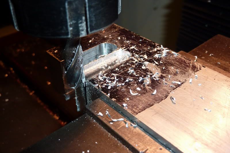
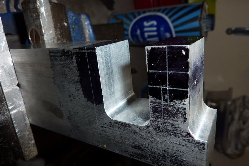
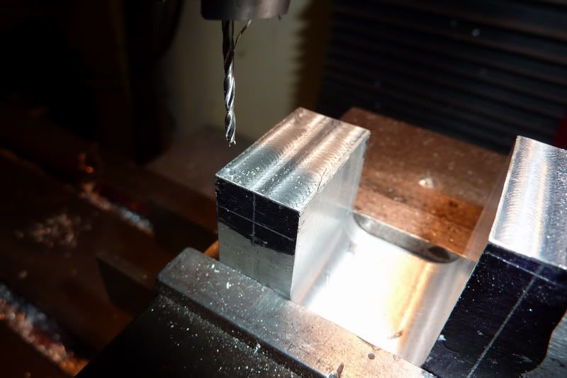
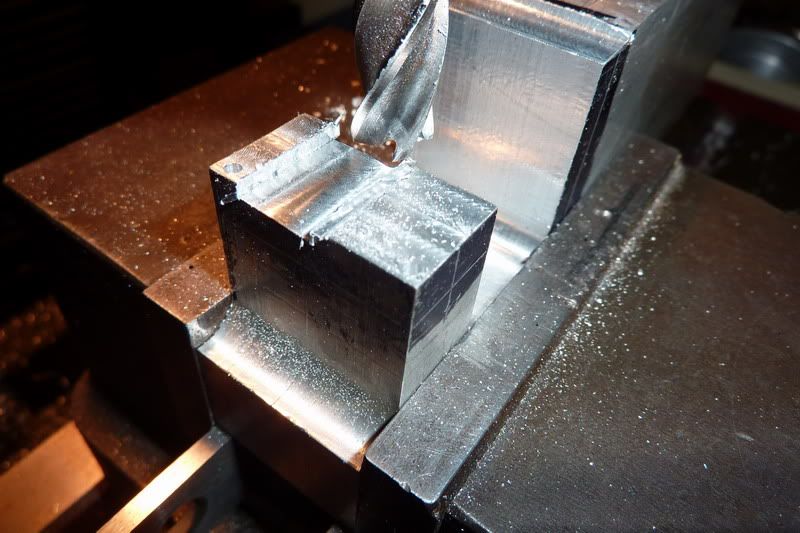
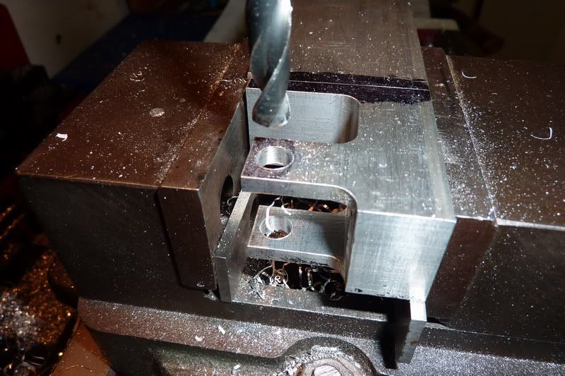
The frame went back into the vice to mill out the middle leaving the radii, roughed it out first:

2011-01-0721-42-22_0001.jpg


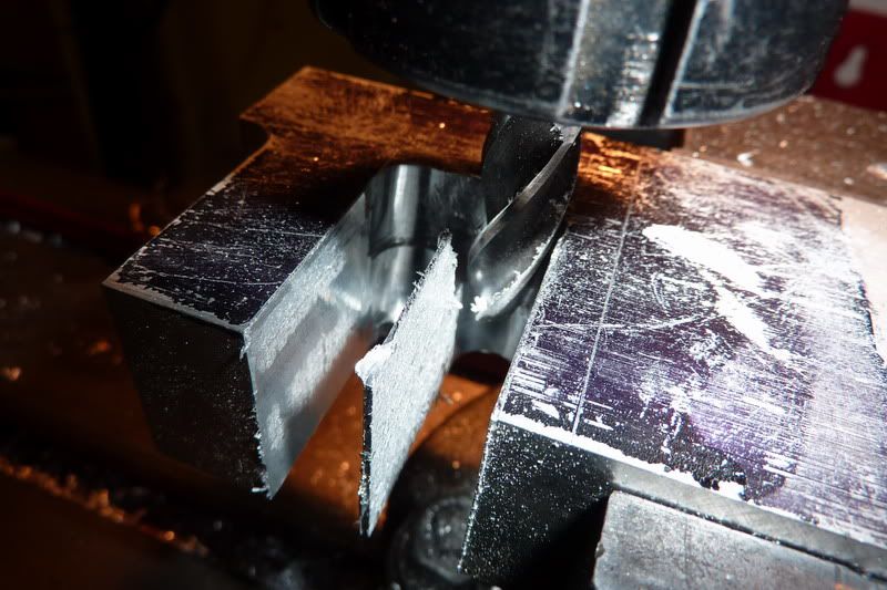
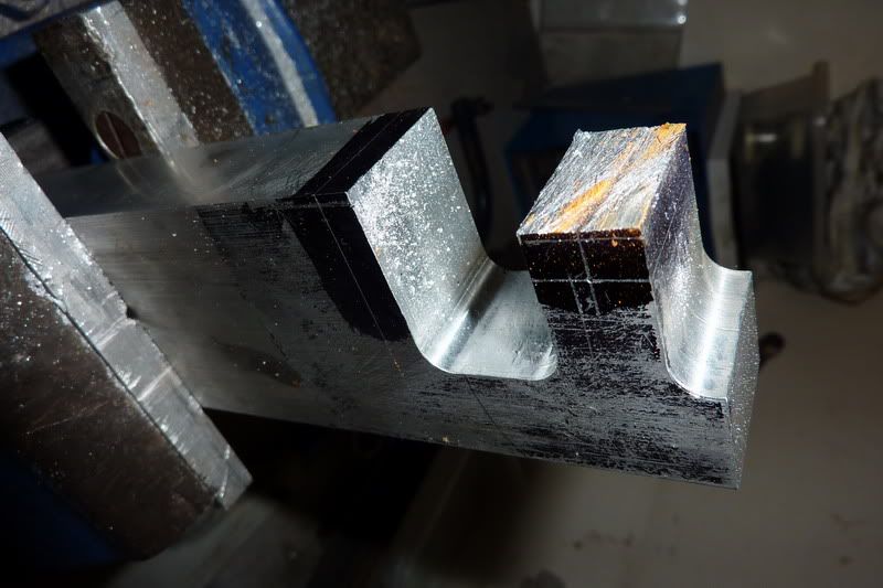
Other side and getting through it now, I wasn't really enjoying this and contemplated handsawing most of it out - but that was taking even longer with an abrafile!

2011-01-0721-59-10_0002.jpg


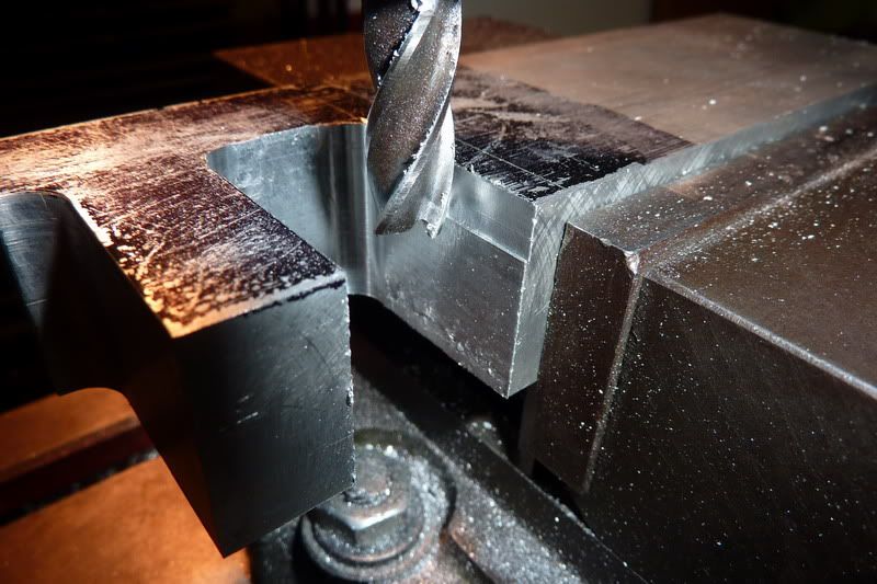
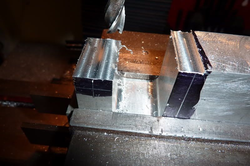
Taking the finishing cuts and climb milled with no extra cut on which gave a decent finish:

2011-01-0722-21-02_0003.jpg


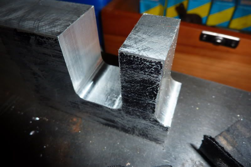
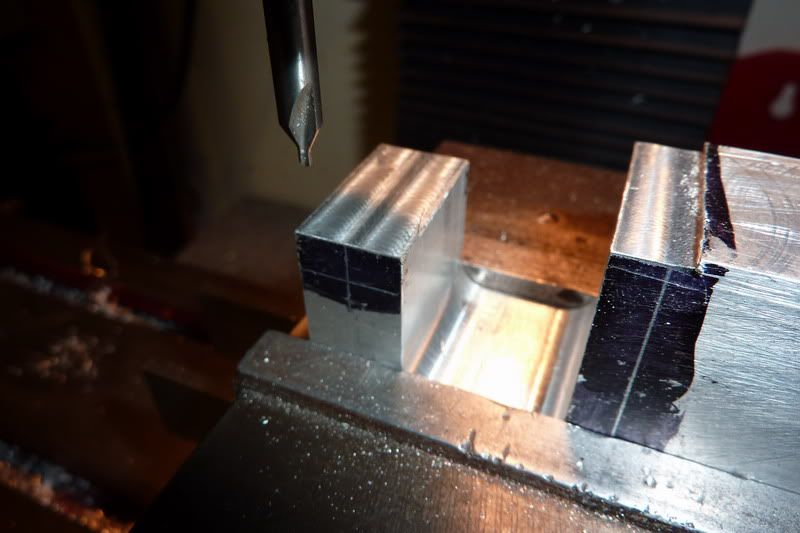
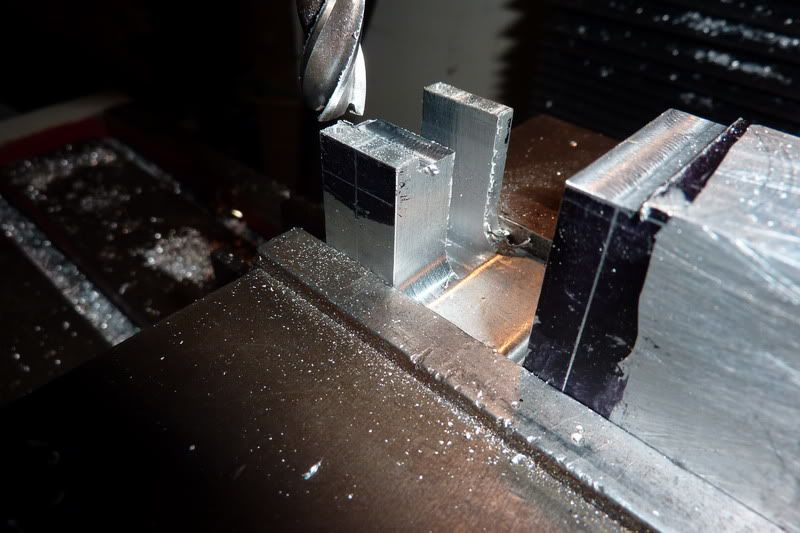
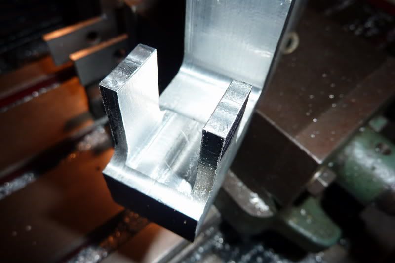
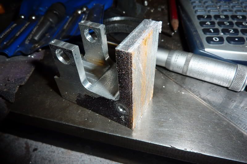
That's the profile milled out and de-burred:

2011-01-0722-29-16_0004.jpg


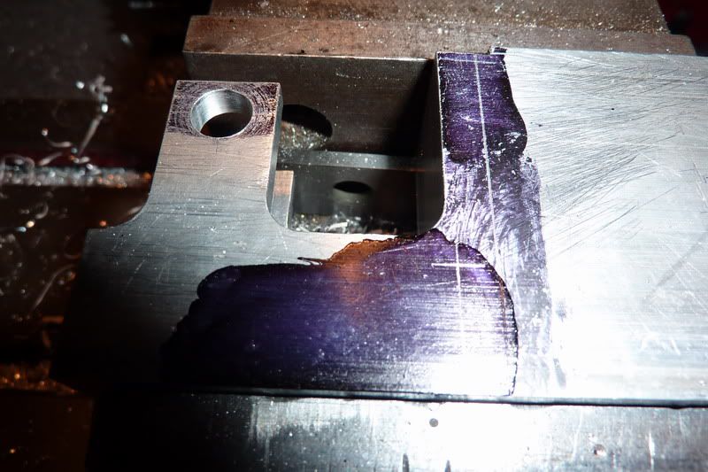
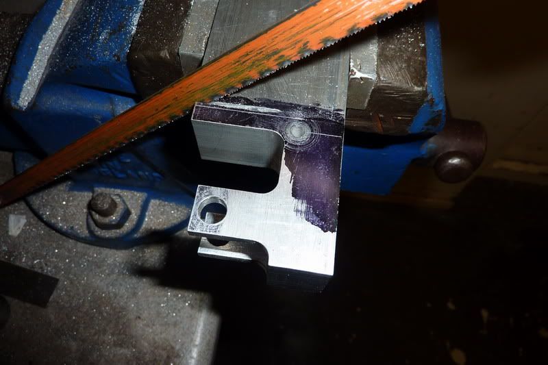
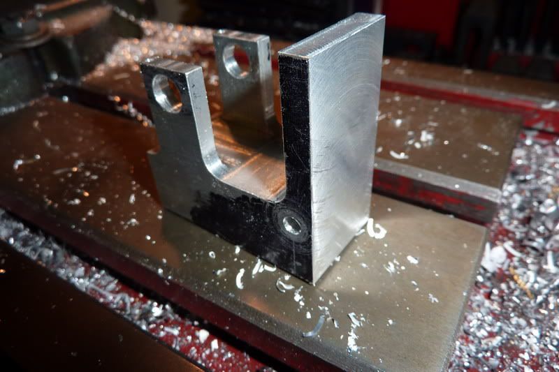
Now I had to flip it in the vice so it was upright and mill to size before milling the slot for the crankshaft. I had a bit to cut off the top of the bearing supports and a bit off the over all thing so marked that out.

2011-01-0722-53-07_0006.jpg


I hacksawed a bit off the top of the bearing supports to save me milling loads off. :doh: Nearly hacksawed on the wrong line at first, the lower one is for the bearing bore - that could have been a disaster!

2011-01-0722-58-13_0005.jpg


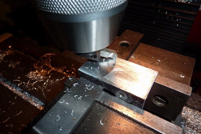
Back into the milling machine but upright as I said to mill to height:

2011-01-0723-05-11_0007.jpg


This is about where I left it tonight as am a bit tired, I've de-burred it and have it clear in my head what to do next thanks to Jim's build notes. I need to drill and tap the holes for the bearing pinch bolts, mill the slot for the crankshaft. Saw off parent stock, invert in vice and finish the cylinder face. Bore cylinder face and transfer bolt pattern from cylinder cover. Flip in vice and mill slots in bearing supports. Finally flip upside down to drill and tap some mounting holes.

I don't think I'm going to bother with the thin metal base, don't see the point really, it can go straight onto the wood.

Thus far I've made 2 of each component but now I'm deliberating whether to drop onto one engine and progress more quickly to keep me interested. Or just battle on and make another frame. hmm ....

Nick
 
Great to see you back on this one Nick!

Glad to hear your vice fix is holding up, you removed a lot of metal from that bar.

Kel
 
Thanks Steve and Kel,

Got a bit more done tonight. Wow, this frame is possibly the most complicated component I've made, it's not been difficult (so far - :lol: tempting fate here) but a lot of work in it and still not finished.

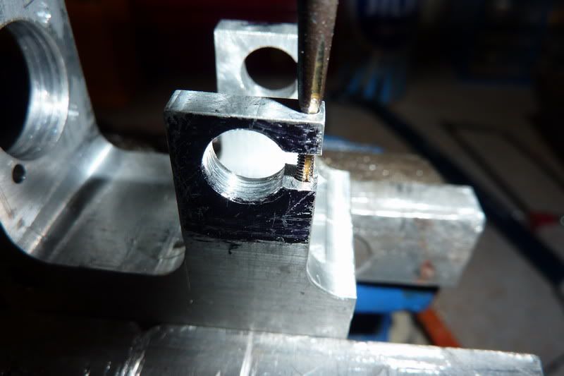
First job was to drill holes for pinch bolts, these are - can't remember size but my equivalent is 10ba, so drilled down with No 54 then opened top out for clearance to No 50. Haven't tapped yet, will do that by hand later:
2011-01-0821-56-41_0001.jpg

2011-01-0822-00-34_0002.jpg


Then start milling away the middle to leave the 2 uprights. Here I just got it some where near the right width then took some small finishing cuts after:
2011-01-0822-25-06_0003.jpg

2011-01-0822-47-16_0005.jpg


Finished milling - took a while, actually I had a cup of tea in between as I thought I was going to get impatient and mess it up! Also thought I'd leave the machine to cool a bit.
2011-01-0823-31-31_0006.jpg


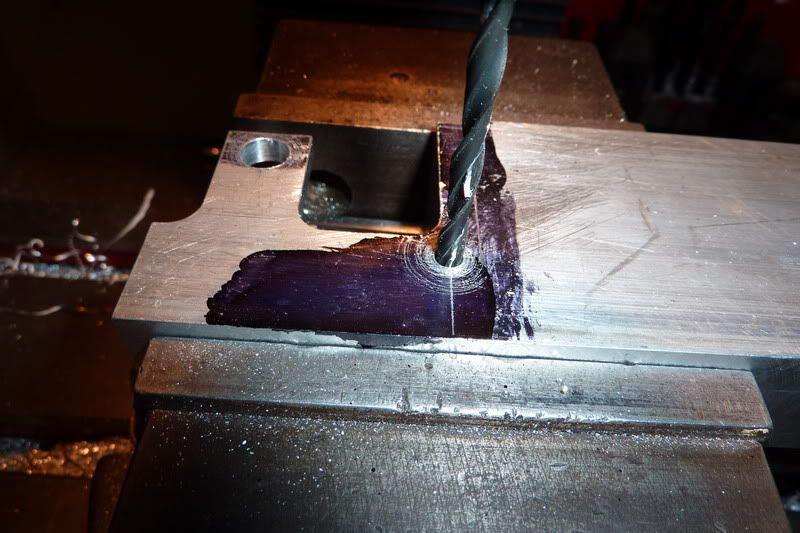
Back in the mill on its side to drill holes for bearings, I centre drilled, drilled through 1, then picked a sturdy ish drill to go through to the other using first as a guide. Then opened up.
2011-01-0823-50-03_0004.jpg


That's it drilled to final size - tried the bearings they are a sliding fit so should be perfect for screw just to pinch. Marked out position of valve pivot.
2011-01-0823-59-51_0007.jpg


While it was on its side I drilled the hole for the valve pivot.
2011-01-0900-06-57_0008.jpg


That is about as far as I got, just de-burred it.
2011-01-0900-15-50_0009.jpg


Still a bit of work here!

  • Saw it off the parent stock
    Mill flat
    Bore large hole
    Transfer cylinder bolt pattern
    Drill valve rod hole
    Mill slots for crank to pass through
    Drill & Tap mounting holes
    Tap Pinch bolt holes

Don't know, maybe it sounds more than it is but I'd say at least another night on it. I need to think of how I can bore it to 11/16" Don't think I've got a drill that big, have a 5/8" end mill. Might have a look at drawings to see if it's necessary to go the same size as the cylinder bore.

Nick
 
Hi Nick,its starting to look like a poppin hope the build goes well for you as they are great fun and great runners.When i made mine I added 7/32 to the overall length of the barrel to allow for a spigot to locate the barrel into the frame it hasn't had any detrimental affect on performance .
best wishes Frazer
 
Thanks guys, hopefully I'll be back on it tonight. More people are trying to convince me to stick to making 2 of each component then I should end up with 2 engines rather than 1 engine and a box of bits!

Frazer, good idea that but unfortunately I've already made the cylinders, it isn't good practice with no locating spigot, I will have to use my jig thing that I made to transfer the holes to the cylinder as there was no spigot on the cover either. I am trying to just follow the drawing on this as never done that before but I will omit the radii on the bearing uprights and the cylinder face, I'm not very good with a file so I'd have to turn up filing buttons for those and that will just take more time I don't really have a lot of to start with! I think I'll go back on my decision to omit the flat base plate though, I've got an idea in mind for that now, it shouldn't take long and should make it stand out a bit.

Nick
 
Been quite a long night and still a bit to go as this will take a while to write up!

Continuing with the frame for poppin..

First job was to saw the job from the parent stock.

2011-01-1021-19-47_0001.jpg


10 minutes with the hacksaw - I did such a good job I thought I'd just touch it up with a file instead of milling.

2011-01-1021-29-45_0002.jpg


Just checking you're awake... I thought I'd try to get it a bit flatter than that so put it in the milling machine and decided to flycut it rather than take loads of passes with a small cutter. Luckily the flycutter was still set up from when I skimmed the block originally.

2011-01-1021-38-53_0003.jpg


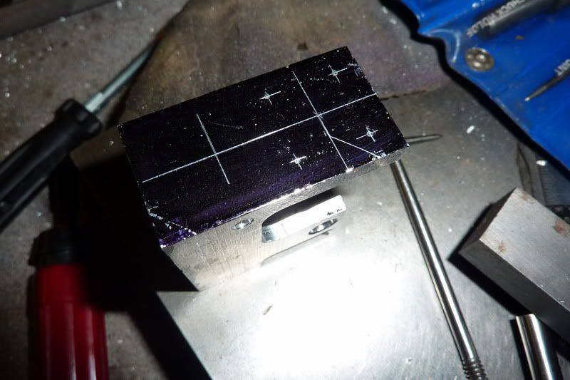
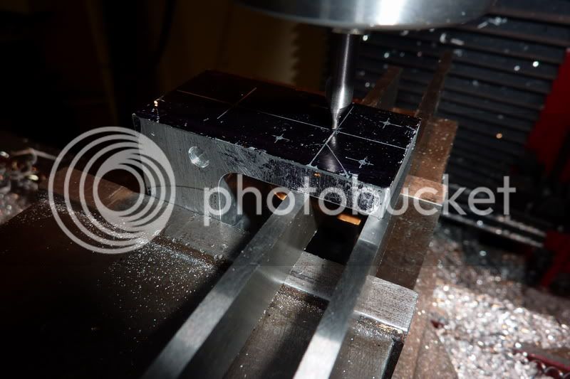
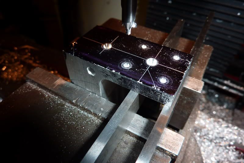
Then it came back out to get marked up for all the holes. (large one for conrod to pass through, cylinder bolting holes and hole for valve rod) I decided that as the width of the standard was 1" and the cyl. cover 1" it was fairly easy for me to just position the cover and mark the holes through.

2011-01-1022-23-23_0006.jpg


Spotting the holes.

2011-01-1022-30-35_0007.jpg


2011-01-1022-35-19_0008.jpg


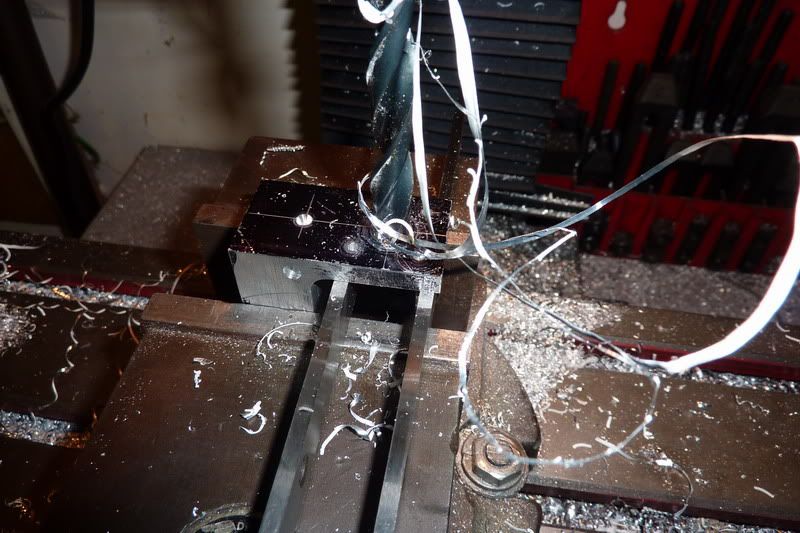
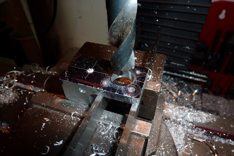
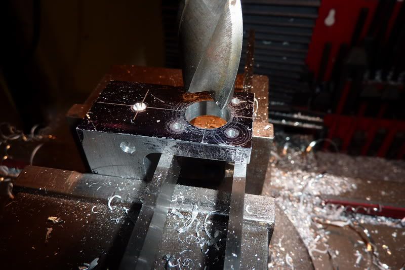
Then starting to open the large one up:

2011-01-1022-43-10_0009.jpg


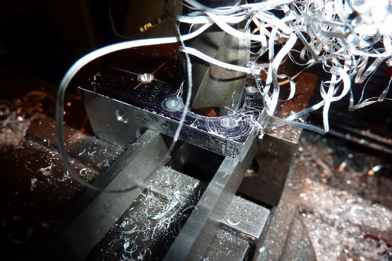
Drills getting bigger and scarier!

2011-01-1022-47-20_0010.jpg


I decided to finish with the closes thing I had to 11/16", a 5/8" slot drill.

2011-01-1022-51-49_0011.jpg


This worked really well and gave a good finish.

2011-01-1022-53-10_0012.jpg


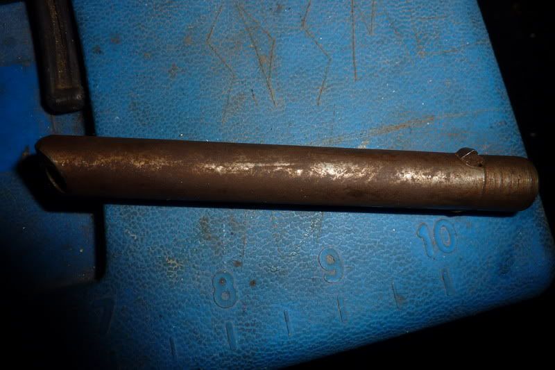
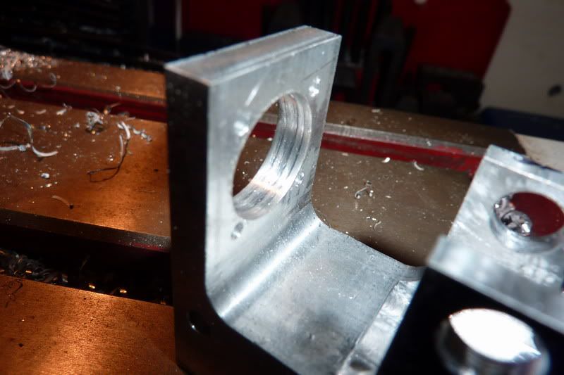
I was going to stop there as I would guess 5/8" would be big enough for the con rod not to foul. But then I thought, no, I better stick to the drawing as couldn't be bothered calculating stuff! So I found an old boring bar:

2011-01-1022-56-26_0013.jpg


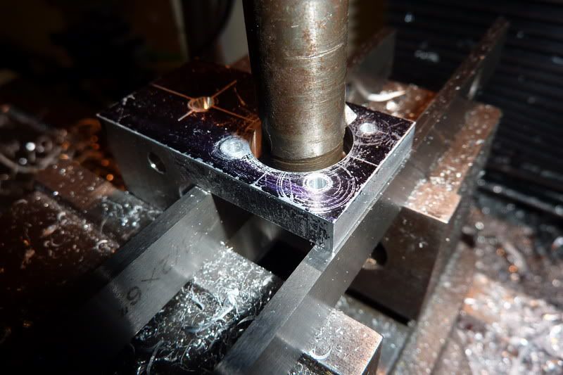
it happened to already have a tool in it. I just had to grind a bit away from the wrong end so it didn't interfere with me trying to measure it to get 11/16". I got as near as damn it to what would give 11/16", put it in the collet chuck and started boring!

2011-01-1023-13-27_0014.jpg


At this point I was pretty scared as it appeared to be wobbling about like a good 'un! No idea why it would do that but I think it was to do with the shape of the tool - it was a sort of v shape but with hindsight I think I should have had a virtually straight leading edge just with some rake angle and a slight clearance. The up shot of this was that it gave a rubbish finish. I think it was partly my haste using the tool that was already there and wanting to stop the operation as I thought I was going to ruin my component.

2011-01-1023-29-02_0015.jpg


I quit with this while I was ahead (well, while nothing was broken!) with the hole at this point. I'll need to practice this boring lark on some scrap and might re-visit it if I get good results I think, or at least I'll get it right for the next frame.

Next, another scary operation. Milling the slot through the bearing holes to enable the crank to pass through. I thought I'd try out my new slitting saw arbor and one of the saws I cunningly kept from my horizontal milling machine. The concentricity of the arbor or saw must be cr@p as you could visibly see the run out (about a mm or so!). I decided as it wasn't moving up or down it should still be ok and turned it by hand a few times with it touching the workpiece trying to get it into what I thought was the best position. I made sure I wasn't climb milling and that when I'd wound it all the way through it'd cut the slot in one pass.

As I neared the workpiece the tinging noise nearly made me have kittens, I thought it was just going to bend the uprights but I thought with a decent speed (about 400 rpm?) and a slow feed it should be ok. I nearly made a massive ****oo though. The slitting saw was 0.1" wide and the slot was to be 0.16". So I started off with the bottom edge 0.080" below the centreline of the bearing holes. Then I'd move it up 0.060 to do the second pass and widen the slot to desired width. If I'd have done that, it would probably have bent the top. Glad I remembered and started at the top first then widened at the bottom where it still had more structural integrity. Sorry, this is getting a bit waffley, anyway, it worked ...

I thought I'd tap the holes next. Another problem here, the 10ba tap is nowhere near long enough to go through the clearance hole and into the portion that should be threaded. It gave me 4 or 5 threads in there max before the shank started to foul - have no clue what to do here. I'll have to read the instructions to see if I've missed a trick.

2011-01-1100-11-35_0018.jpg


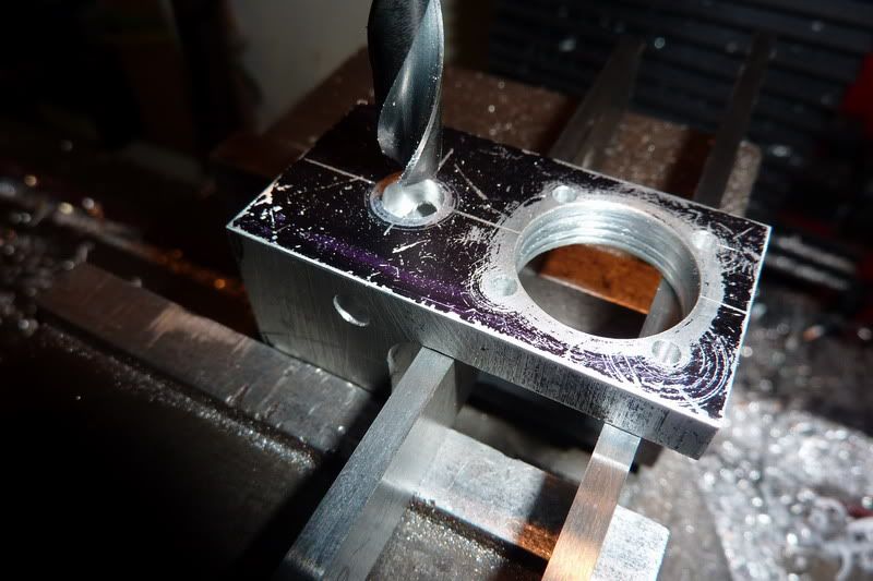
The last thing to do was to drill the 1/4" hole for the valve rod that meets the cross hole for the valve shaft:

2011-01-1100-07-41_0017.jpg


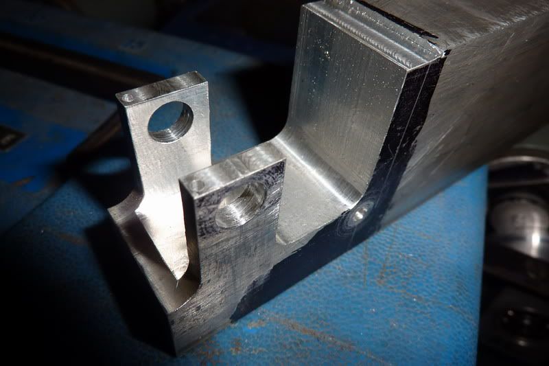
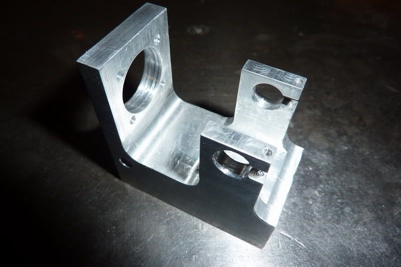
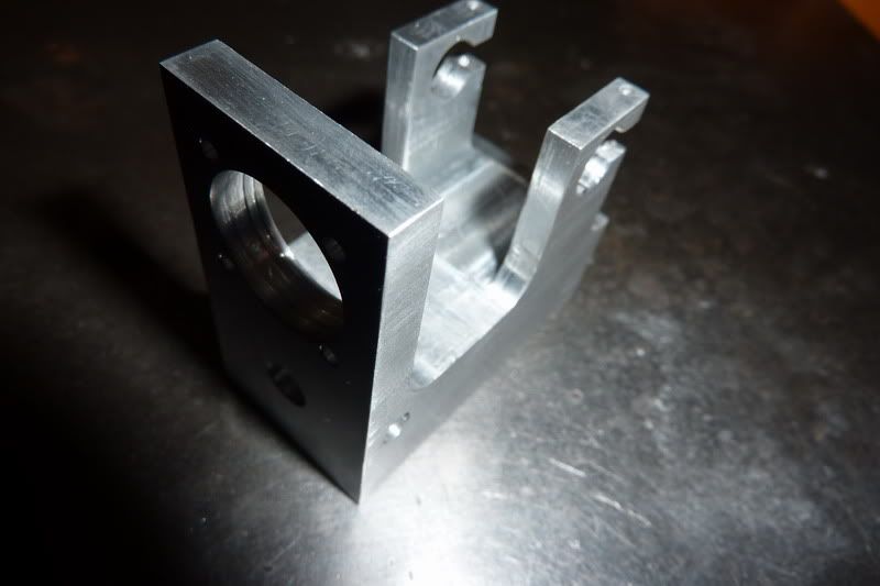
That went well. I cleaned the thing up a little and here is the finished standard or frame:

2011-01-1100-28-12_0019.jpg


2011-01-1100-28-21_0020.jpg


Actually it's not finished - I forgot to drill any mounting holes in the bottom but was too late to start, don't want to ruin anything due to being too tired!

I really don't want to make another one of these right now. I think I want a change of scenery so to speak so might crack on and make some other parts and come back to the 2nd frame!

Nick
 
Oh, forgot to put this one in, a shot after flycutting:

2011-01-1021-58-17_0004.jpg


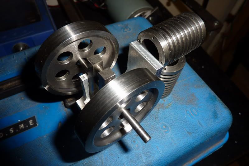
and I couldn't resist this mock up, this was earlier on before I'd (nearly) finished the frame!

2011-01-1021-59-36_0005.jpg
 
Looking good nick
I hope this one runs easier then the last one what a challenge that was :bow:
Jamie
 
Thanks Jamie, I hope so too! I might go for a graphite piston instead of cast iron this time - worth a try I reckon.

Nick
 

Latest posts

Back
Top