'Poppin' Flame Licker Engine

Home Model Engine Machinist Forum

Help Support Home Model Engine Machinist Forum:

This site may earn a commission from merchant affiliate links, including eBay, Amazon, and others.
Good job with the wheels Nick and a great idea using the hex as an index aid that ones files away. Don't worry about the slow pace just enjoy what your doing its amazing what you can do in small steps.

Have fun

Stew
 
Deanofid said:
I hope you don't mind me saying, but don't worry about the motivation thing. We all have little spells of that. Me too, at the moment, and for the last few weeks. After working on someone else's stuff all day, sometimes you just feel like relaxing in the evenings. Just saying, you're not the only one.

This is good to know, that's exactly how I feel, but thanks Kel for your motivational words too, that is ultimately what I do it for.

I think in future my write ups may be limited to a few words about what I am about to do, then a few pics / video of the final thing and a brief description of how it went - I'm finding that taking photos in the shop distracts me, then resizing, uploading and writing up takes a lot of time that I could spend actually making things! So my projects are taking maybe twice as long I would like. Then again, it's more fun sharing what you're doing on the forum and getting praise, feedback and advice along the way too.

I like seeing a finished result quite quickly which I think is why I've never finished any larger projects. I doubt if I'll ever get my 5" gauge sweet pea locomotive done as that would take many years!

Plodding on anyway. Hopefully tonight I'll be onto something different, crankshafts I think.

Nick

 
At one time Nick, it used to take me many hours of photo conversion and writing up a medium length post.

By using this,

http://www.faststone.org/FSResizerDetail.htm

I can do all my pictures in a couple of minutes. Once you get used to it, you can resize, colour correct, even watermark in a matter of seconds, every picture chosen comes out posting ready. The main part is choosing which pictures you want to go into the post. It is totally FREE to home users and one of the best quickie manipulators I have come across.

You still have to do the write up, which can sometimes take a couple of hours, but this program has taken it from a chore to a pleasure to process my pics. Hence I put a lot of piccies in my posts.

Blogs
 
Great idea for drilling the holes in the Flywheels Nick, I'll have to remember that!

Vic.
 
Hi Nick, it just goes to show the importance of having a tool ground properly for the job. You couldn't use this one for a dual purpose because your top clearance would give you a negative cutting angle on the other side plus you'd be below center quite a bit. Over the years you'll end up with many different configurations of tools. Sooner of later they'll get used again.
gbritnell
 
Thanks John, the software I am using isn't too bad but might give that one a go.

Yep, good point about the tool George. I really wish I had a QCTP with loads of holders!

I've just counted up the number of parts I have left on this build and it's 16 components / jobs to do X 2 for the two engines! I reckon it works out that there are 16 of my nights work left, so I might get this done by the end of March - I need to get it looking like an engine then I will be more motivated to get it finished as it starts coming together!

Nick

 
A little more progress - not as much as I would of liked, but a little.

I got the crankshafts just about done.

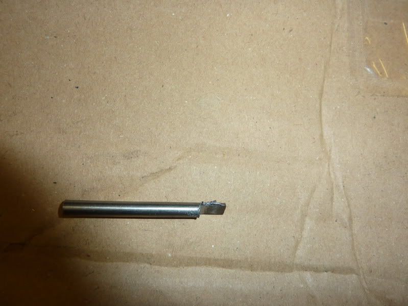
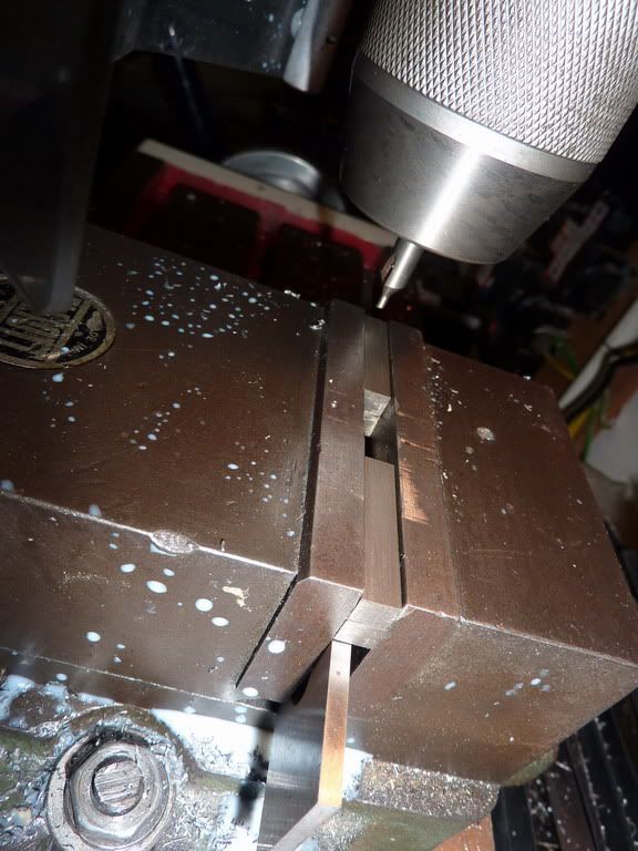
I thought I'd be clever and try making a 'D' bit out of a bit of the silver steel that would become the crankshaft - that way I could accurately size the holes in the crank webs etc and flywheel bosses.

Here it is:

2010-03-0622-10-04_0002.jpg


Later found out that didn't work though, think I must have milled just too much off as the D part went into the hole I had drilled too easily. So I used a number drill instead.

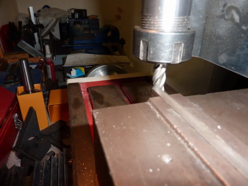
Milling a square end on the bar:

2010-03-0622-26-34_0003.jpg


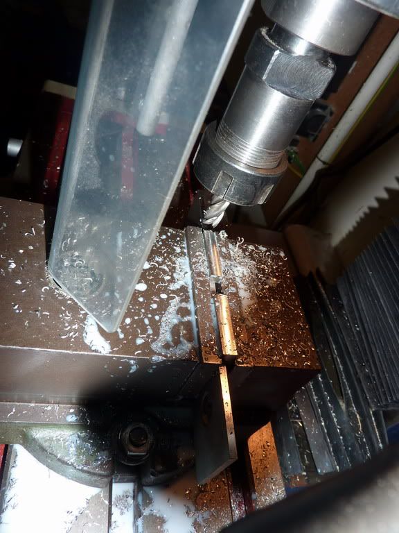
Milling down to correct thickness:
2010-03-0623-16-53_0005.jpg


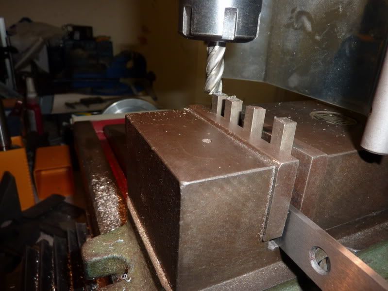
Setup for milling webs to length - this didn't work so had to do 1 at a time and mill across the vice at same height setting in end:
2010-03-0622-43-30_0004.jpg


Setup for drilling holes:
2010-03-0623-34-20_0006.jpg


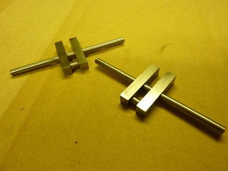
Pair of cranks with loctite curing before I cut out centre section of main shaft:
2010-03-0722-16-28_0007.jpg

 
You would be well advised to drill the webs for roll pins and install them before cutting away the central section. DAMHIKT.
 
Marv,

I was wondering about that, would the sawing be enough to dislodge them - I was hoping not as loctite is strong stuff. I think the loctite would certainly be ok in normal use - there will be very little torque exerted about the joint in running, but sawing might be a different matter. Some people mill the central section out but I thought a junior hacksaw and a touch with a file after would be more gentle.

Just googled the acroynm - ok!

One question then, do you just put parallel pins in and loctite or tapered pins? The last thing I want is for these to fall to bits, I would be gutted and probably get annoyed and chuck the lot in the bin!

Thanks,

Nick
 
Nick,

I'm a bit of a cheapskate when it comes to making things like this,

A couple of small soft steel nails do a great job.

Mike them up, and drill a hole thru your parts as close to size as possible, if you can get a slight interferrance fit, then all the better. Very slightly countersink both ends of the hole, and pop the nails into holes (with a touch of loctite on if you want to). Cut the length until there is about 1mm protruding on one side and flush on the other end.

Now put the flush end onto a hard surface and give the protruding end a little tap with a metal hammer. That should expand the sticky out bit just a tiny bit. Now turn over and start to hit the other end of the nail. You should find that the countersink fills up with metal, again turn over and tap the top side. Eventually, after a few seconds, both countersinks will be full of metal, file the rest off flush, and rub over some W&D. You will find the joints almost invisible, and you will have a rock solid crank. You can repeat on the crankpin, and if things go slightly out of line or twisted, just clamp everything up in your milling vice and it will all be square again.

Then cut the bit of metal away.

Blogs
 
Thanks John,

I will do that, I couldn't bare the thought of it moving! I never thought that it's more beneficial to have something soft to be able to spread it out, I was going to put some more silver steel or stainless. I have some soft iron 1/32" rivets that might do the trick.

I forgot to mention, I will be trying the 'D' bit again after reading your post from before. I need to concentrate more on getting down to size and using micrometer to check. Here I just touched on and used the quill DRO which wasn't good enough and must have taken too much off rendering the D bit useless.

Hope you're improving.

Nick
 
Nick, to hold the crank together I pressed in some old neelde bearings from an outboard motor. These are hardened steel I beleive, after I hammered them in I used the sander to file them down.

Using a soft material is a much better Idea, these needle bearings dont bend, only break.

I thought before I did this, could I just solder the parts together? Or Would the heat from the torch warp the steel?

kel
 
Kel,

Thanks, I've see people solder them with good results, I can never get the damn thing cleaned up properly after soldering though so I've opted for loctite. This is the first time I've made any crankshafts like this as all my others have just been a crank disc and pin sticking out of one side

I don't know how you completed yours so quick - I just keep remembering more and more parts I still need to make! Hats off to you.

I think this engine has more parts than any I have made before.

Nick
 
Nick, I was only able to get it done so quick because I had a few weeks off work, due to bad weather. Also, I practicaly live alone now, so naggin is pretty much a non issue. Plus, I get really excited once I begin a project, I dont stop till its done. The status of my social life reflects this. I turn into quite a recluse when I get into something.

kel
 
Sounds great to me Kel! ;)

I keep dreaming of a nice warm room in the house kitted out with small machines for little projects like this but don't think I'd ever get away with it!

Nick
 
Thanks for those links Vic, I might try the top one too. It's strange he recommends 1 thou below centre for the type I tried.

Need to do some experimentation on this.

Nick
 
Started on the frames tonight, or standard as the designer calls it. I bought a length of 1" x 2" aluminium for this. The idea is supposed to be to machine the profile on the end of the bar sticking out of the vice, but my vice doesn't grip when at it's maximum opening - I remembered having problems with my cylinder for the last flame gulper.

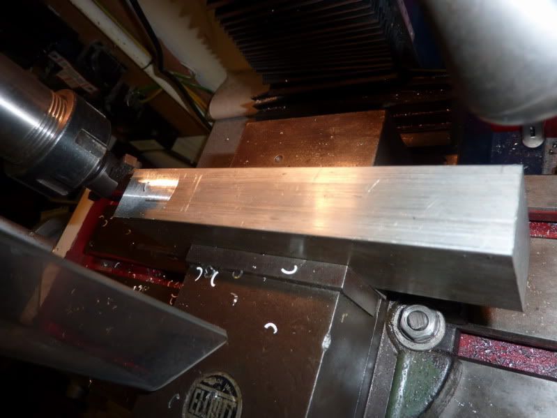
So I had to flycut the material down a bit first:
2010-03-0921-16-20_0001.jpg

First time I’d really flycut anything and it went well, or at least I thought it had but when I measured it, the bar was about 20 thou different end to end. The milling machine is cutting on a taper – which means either the vice is not made properly, or the milling machine is not made properly – I’m guessing the milling machine. When I got my machine 2 of us bought the same one to get a discount, I know the other guy had a problem with his table being tapered. Will have to check mine now.

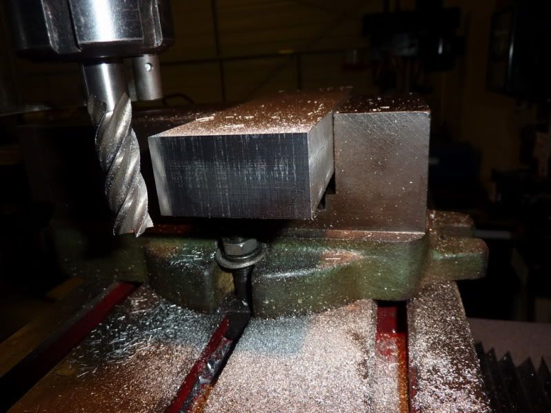
I could now remove the jaws from the vice to get a bit better grip (faulty vice) and grip to mill end square:
2010-03-0921-56-31_0002.jpg


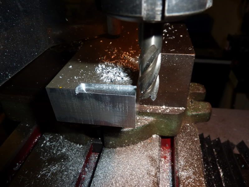
Next I milled the bit off the end leaving a radius, this took a while, I was taking cuts of around 3/32 – 1/8”:
2010-03-0922-18-11_0003.jpg


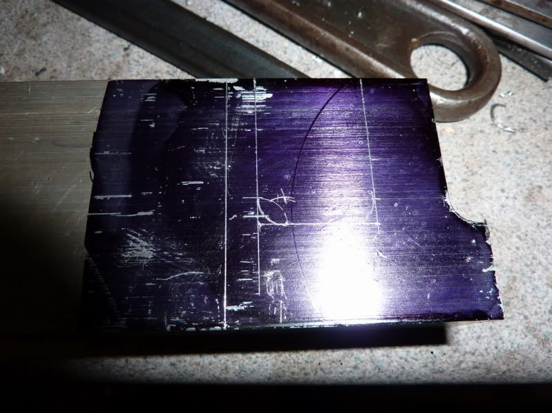
I then decided to mark the thing up as it was a pain trying to use the graduated dials – and I know they are not that accurate, really need some sort of DRO setup:
2010-03-0922-49-16_0004.jpg


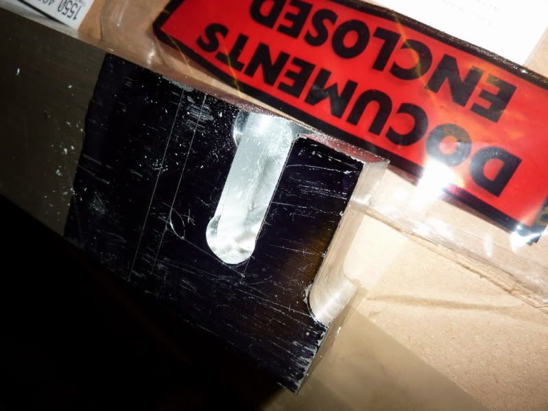
I then started milling the other section out to leave the 2 rads, but this is as far as I got:
2010-03-0923-19-48_0006.jpg


When I went to mill along, the metal moved in the vice again – no damage done but just no grip.
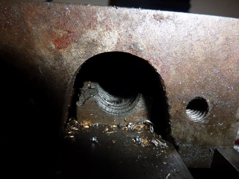
Whipped the end plate off the vice and found this:
2010-03-0923-18-27_0005.jpg


The casting has cracked at some point leaving only half a nut for the screw to screw into – hence at wide openings if you try to get a decent tightness, there is enough play in the bearing to let the screw ride up on the threads and jump out of mesh. Don’t think this will be particularly easy to fix but will have to have a look. I don’t think it’s something that’s just happened as the broken bit is nowhere to be seen. Probably always been like this, I’ve just been getting away with it for small openings as the nut is engaged closer to the bearing, hence there isn’t enough play to let it ride up and jump out of mesh with the screw.

So probably on the look out for a new vice now as not too hopeful of being able to repair this one – shame as it is, or at least was a good vice – Elliot.

Nick
 
Nick, thats too bad about the vice.I hate buying tools twice. Amazing it ever held while milling with half a nut.

I noticed you have a hold down clamp set. You could clamp the bar to the table with spacers and mill it out from there.

When I made the frame for mine I did not leave it as part of the bar. Instead I started with a block the excact size I needed. From there I drilled the holes for the cylinder and bearings, then I milled out the middle with it in the verticle, or upright position. I got round inside corners using a 1/2" ball end mill. This just seemed easier to me. But thats me.

kel
 

Latest posts

Back
Top