Philip Duclos "Odds N Ends" hit and miss engine

Home Model Engine Machinist Forum

Help Support Home Model Engine Machinist Forum:

This site may earn a commission from merchant affiliate links, including eBay, Amazon, and others.
Okay---We got joy!!! We got so much compression now that the flat belt won't drive it---it just slips. I have went back to the adapter that drives right on the end of the crankshaft, and the engine is starting and running for short periods of time. Office is full of blue smoke. Twiddling ignition timing and fuel needle valve, trying to find the "happy" combination.

where did you get all that compression??
 
Luc--I got all that compression by swapping out the piston with cast iron rings for a new piston with a viton o-ring. I discovered that I had one spare 1" viton o-ring left from my Atkinson build. It made all the difference in the world!!!
 
Luc--I got all that compression by swapping out the piston with cast iron rings for a new piston with a viton o-ring. I discovered that I had one spare 1" viton o-ring left from my Atkinson build. It made all the difference in the world!!!


That great news Thm:
How do you like my sugestion of that small pin over your ring?
 
That great news Thm:
How do you like my sugestion of that small pin over your ring?


Honestly, that suggeston only applies to an engine with ports in the sleeve to keep the ring from rotating. Other than that....I dont see your point...
 
Brian, Im curious. You say the ring shows a good wear pattern. How about the bore? Did it look ok as well? How much piston to wall clearance? I was planning on running iron rings on my build and am trying to figure out why they just dont work out for you. Im not used to model engines, so there is much I need to learn...
 
Brian im proud for you.. Glad you got it running , even a little bit. Just have to tune it now.. But as Aonemarine said im planning on using cast rings on the Webster also. I sure wished you could have got the cast rings to work. But congrats for getting it running..Bill
 
Honestly, that suggeston only applies to an engine with ports in the sleeve to keep the ring from rotating. Other than that....I dont see your point...

not quite wright. :confused: because if a ring is set up properly and this means
end gap and side clearence it wont rotate. I't beeing use in a two stroke
to prevent the ring to rotate when worn out and wrecking a cylinder for nothing.:(

If it's place "the pin" in the drawing " properly" it will have the effect of reducing ring gap lost by half or blow by whatehever you want to call it

sure "but gap" ring clearence is not the best (what's beeing use here )

you could also try angle gapping and youll be surprise what the difference
it makes.
I really hope Brian will try it after he will use cast rings or make is own:D
 
"If it's place "the pin" in the drawing " properly" it will have the effect of reducing ring gap lost by half or blow by whatehever you want to call it"

Not so, you still have to allow for ring expansion. otherwise the ring expands to the pin and will wedge itself to the cylinder walls. I used to build outboard engines for drag racing and built thousands of 2 stoke outboards as well as 4 stroke engines. Trust me rings can and will rotate if they want to especially when they run over a port.....But thats better left for discussuion elsewhere and not on Brians post.
 
ring info that many should read :)

ring info from OTTO.jpg
 
Im not arguing that, but build yourself a high performance outboard with a ported sleeve without the locating pins and see what happens. I have and its not a pretty sight!! Especially with a keystone ring at 14k rpms. 2 stroke outboards are a different beast than thier 4 stroke brothers. Thats why 2 strokes have the pin and 4 strokes dont.
 
This was my first ever attempt at running cast iron rings. The cylinder is cast iron, and the piston was cast iron. the rings were purchased from a reputable comppany in Texas, and they were visually perfect. I checked the ring gap in the cylinder, and it was perfect. The ring grooves I machined in the piston were as perfect as someone with 5 years machining experience, good machines, and a very good understanding of all things mechanical/technical could make them. The cylinder bore was drilled to withing .030" of full size, then reamed to size with a straight flute machine reamer in the lathe. Then it was rough honed with a spring loaded brake cylinder hone and very light machine oil to take out any large machining marks. Then it was lapped with an aluminum lap .001 to .002" smaller than the bore, using 600 lapping compound with the lap locked in the lathe turning at 115 rpm while the cylinder was held by hand and worked back and forth on the lap as it was turning for about 2 to 3 minutes. the cylinder was then flushed with laquer thinners and warm water and soap to remove any traces of lapping compound. The piston was an air tight fit in the cylinder. That is to say, it would fall thru the cylinder under its own weight, but when a coating of light oil was applied, one finger held over the end bore would stop the pistons movement because of the air trapped ahead of it. Thats about as good a fit as you can get. Why did the rings leak? I have no idea. The gaps were arranged at 180 degrees to one another. The piston with rings installed was at first terribly stiff in the bore of the cylinder, even when coated with light oil. After a 1 hour run im period on the lathe, using light oil during the whole breaking in process, the piston freed up to the point where it could be moved in the cylinder by rotating the crankshaft by hand. After I decided that the rings were not going to hold compression for me, I did some forensic examination. The rings were uniformly shiny all except for one area on the side of the top ring which was not as shiny as the rest of the ring. To a lesser extent there was the same "not quite so worn" area on the second ring, but on the opposite side. Perhaps, on a much longer run in perios the rings would have worn in more uniformly and sealed 100%. I don't know. This was my maiden trial with cast iron rings, and I won't use them again. Thousands have used them succesfully. Hundreds have used them and got the same poor results I did. When I put in the new piston I made yesterday morning with a 1/16" cross section Viton o-ring on it, it sealed immediately and totally, and gave me wonderfull compression. Thats all the information I can give you about my experience with cast iron rings.
 
Last edited:
I have found that when putting in cast iron rings into a cylinder you do not want to over do the cylinder lapping you want the finish in the cylinder to be somewhere between a 32 -16 finish.
Now with an o-ring you would want as smooth of finish as you could achieve. The reason you don't want a smooth finish is the rings will not seat correctly or take a long time to do so.
I personally bore my cylinders and try and get a good finish with the boring bar and not lap at all, cut lines around the cylinder will not hurt, it is only if you have depressions from cutting running the length of the cylinder that will cause problems.
I have seen where a builder has tried to make the cylinder with a supper finish inside only to have problems trying to get the rings to seat properly.
This has worked for me on all my IC engines I've built. I feel it's the same as putting in cross hatching in the full size motors to help the rings seal to the cylinder wall.
 
Brian, the spot on the rings where it showed less wear. Where is it located in reference to the ring gap?
 
Brian, the spot on the rings where it showed less wear. Where is it located in reference to the ring gap?
Just to the left of the ring gap in both cases. In all truth, it looks like with another 2 hours or so of running in, the ring would have had the same uniform finish all the way around. However, if the engine won't start and run its never going to happen. Probably on multi cylinder engines with larger displacements, the engine would have started fine and the rings would have completed their "wearing in" to give a perfect seal. However, on a single cylinder, one mousepower engine, it wasn't going to happen. however---I'll make anybody interested a deal!!! I paid $20 for the rings, which included the shipping. I built the 1" piston from grey pearlitic cast iron. If anybody wants the piston and the rings, they can have it for $20 plus shipping.---Brian
 
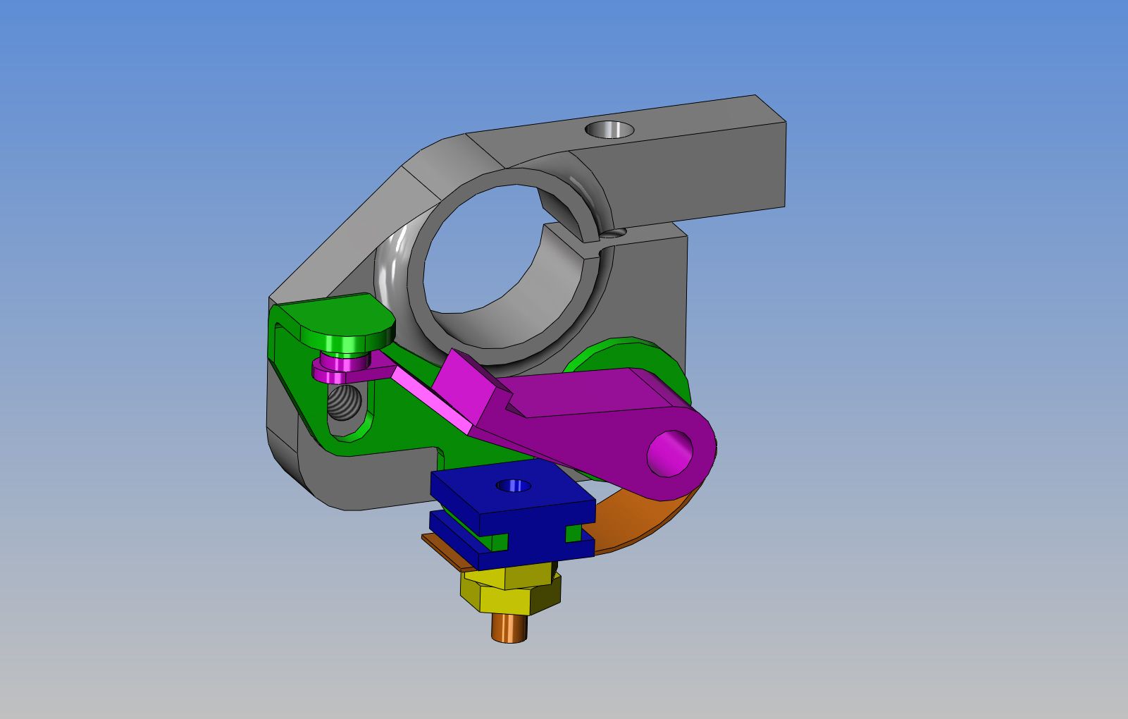
I'm going thru the whole spectrum, ruling out anything that would cenceivably keep this engine from running. I need 3 things--Compression--ignition, and fuel. The cast iron rings were bleeding compression, and the engine wouldn't even fire. I made a new piston and put a Viton o-ring on it, and immediately had good compression. The engine fires quite regularly now when being powered with the electric drill, but not enough to stay running more than 10 or 15 seconds after the drill is taken away. Okay, I'm down to ignition and fuel. Today I tried to make a new needle valve but wasn't terribly succesfull---I just don't have the right machinery for it. The rather hokey home made point set up is suspect also---So, today I "invented" a points mounting plate that will still be adjustable like the original design (I like that capability) but will use a set of tried and true Chrysler product ignition points. I designed it and machined it this afternoon, and tomorrow I will install it and hopefully eliminate any question about "ignition". I phoned all over North America today, trying to find a pre made needle valve with a 2-56 thread on it, but nobody has one. Some model airplane engines (Cox) has a needles valve for $4.00, but the thread is a #2-80 which is a proprietary thread and the tap is not available. I was just about to go online and check out toolpost mounted grinders from Little Machine Shop to use when making a new needle valve when I seen your message.---Brian
SUBASSY--POINTSONBKGPLATE-ODDSNENDS_zps0fa01372.jpg
 
Last edited:
Brian, switch to the methanol... its less tempermental about running rich... Kinda a stupid question, are you running in the right direction?
 
Brian, you can make a really good needle valve by soldering a sewing needle into a brass screw. Phil Duclose used this method in his later engines, I think starting with the Topsy Turvey. I've done this several times and it's dead easy to do, believe it or not. I'll scan a drawing for you if you're interested.

Chuck
 

Latest posts

Back
Top