Its my turn to ask a question. Tomorrow I am going to start making a crankshaft. I have turned two cranks from solid stock. One was a great success, one was garbage due to a misaligned tailstock. Both were a lot of work. I believe that for a small air powered engine, the strength of a one peice crankshaft is dramatic overkill. Other crankshafts I have made by reaming, dowelling, and silver soldering. The only issue with that is that when I silver solder, invariably I make a heck of a mess, and end up having to machine off 90% of the solder that I have just applied--which has run all over the bearing journals where I didn't want silver solder. I am now considering a built up crankshaft with reaming, dowelling, and Loctite. My reamers are all "slip fit" reamers----That is to say that the hole they create is a "nice sliding fit" for a peice of cold rolled shafting. Would I be better off buying an undersize reamer, thereby creating a press fit---Or would that defeat my purpose by scraping off all the Loctite and rendering it innefective. I will be using 5/16" diameter cold rolled steel round rod for the crankshaft, and probably (because I already have them) 0.094" dia split dowel pins. The "throws" will be 1/2" x 1/4" cold rolled flat bar. ---Brian
You are using an out of date browser. It may not display this or other websites correctly.
You should upgrade or use an alternative browser.
You should upgrade or use an alternative browser.
Overcrank Single Cylinder Engine
- Thread starter Brian Rupnow
- Start date

Help Support Home Model Engine Machinist Forum:
This site may earn a commission from merchant affiliate
links, including eBay, Amazon, and others.
- Joined
- Dec 2, 2008
- Messages
- 971
- Reaction score
- 9
Brian Rupnow said:I'm quite surprised at how well everyting slides when all the bolts are cinched down tight. I'm not sure whether that is a testament to good machining or just outrageous good fortune.
Probably both, Brian, but don't forget to add careful design to the choices. Its looking great!
Jerry
Thanks Jerry. I guess since I plan on building this tomorrow, a drawing would be in order. WARNING WARNING--I got thinking about this last night and decided that I needed two raised bosses to keep the con rod from floating around, so the drawing has been modified.
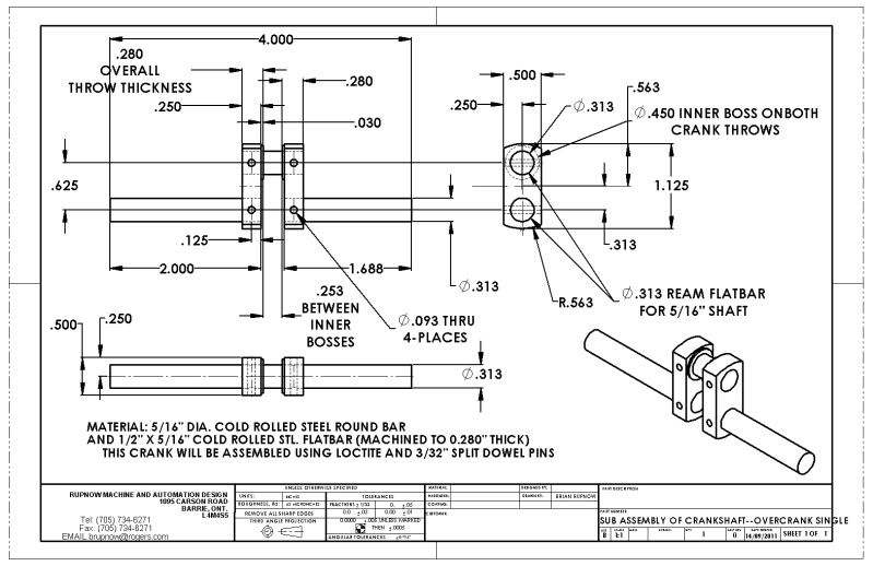

Aermotor8---Thank you, your thread does make excellent sense, and its one I hadn't thought of. Please tell me more about the tapered pins, and what type of hole you use for them---a straight hole or a tapered hole, and if its a tapered hole, how do you taper it.---Brian
I just did some sluething (detective work) with my suppliers and came up with the following.---I can buy a #5-0 tapered reamer which has a 1 3/16" flute length, is 0.0966" dia on the big end and and 0.0719 on the small end. It takes a #5-0 tapered pin, which another supplier is trying to source for me. Nobody knows what drill size you use first, before the tapered reamer. The size range sounds about right for use with a 5/16" diameter crankshaft, but I am totally in the dark on this subject, having never used a tapered pin in my life.---and my supplier is quoting me $22.00 per reamer.----Brian
- Joined
- May 14, 2011
- Messages
- 684
- Reaction score
- 189
Brain P.M.Research has tapered pins and reamers that are smaller. Look at www.pmresearchinc.com hope this is of help. Dale

$171.00
$190.00
Genmitsu CNC 3018-PRO Router Kit GRBL Control 3 Axis Plastic Acrylic PCB PVC Wood Carving Milling Engraving Machine, XYZ Working Area 300x180x45mm
SainSmart Official

$104.99
Sunnytech Hot Air Stirling Engine Motor Steam Heat Education Model Toy Kit M16-CF
stirlingtechonline

$26.89
$34.99
Peachtree Woodworking Supply Bowl Sander Tool Kit w/Dual Bearing Head & Hardwood Handle, 42 Pieces Wood Sander Set, 2 Hook & Loop Sanding Disc Sandpaper Assortment, 1/4 Mandrel Bowl Sander
Peachtree Woodworking Supply Inc

$599.00
$649.00
FoxAlien Masuter Pro CNC Router Machine, Upgraded 3-Axis Engraving All-Metal Milling Machine for Wood Acrylic MDF Nylon Carving Cutting
FoxAlien Official

$99.99
AHS Outdoor Wood Boiler Yearly Maintenance Kit with Water Treatment - ProTech 300 & Test Kit
Alternative Heating & Supplies

$40.02
$49.99
Becker CAD 12 3D - professional CAD software for 2D + 3D design and modelling - for 3 PCs - 100% compatible with AutoCAD
momox Shop
![DreamPlan Home Design and Landscaping Software Free for Windows [PC Download]](https://m.media-amazon.com/images/I/51kvZH2dVLL._SL500_.jpg)
$0.00
DreamPlan Home Design and Landscaping Software Free for Windows [PC Download]
Amazon.com Services LLC
- Joined
- Jan 17, 2009
- Messages
- 887
- Reaction score
- 82
Brian
I fixed my webs with soft wood working nails, make the holes a tight fit and nock the nails in swell the ends over, this swells them good and tight in the hole, a bit crude I know but it works for me.
Stew
I fixed my webs with soft wood working nails, make the holes a tight fit and nock the nails in swell the ends over, this swells them good and tight in the hole, a bit crude I know but it works for me.
Stew
Thanks Stew---I think I like the tapered pin idea, but I can't get ahold of Aermotor8 just now to pick his brain in regard to the taper he actually used. None of the toolshops around here seem to have any knowledge of such small tooling, and are telling me things like one week delivery for #5-0 tapered pins. I did check the site recomended by Dalem9 but PMResearch wants $36.00 for what appears to be the same reamer as my toolshop can get for $22.00---I have other things to build while I wait for Aermotor to respond. I have painted myself into a corner here, and can't turn the bosses on the crank throws untill I find whatever method I will use for pinning them to the shafts.---Brian

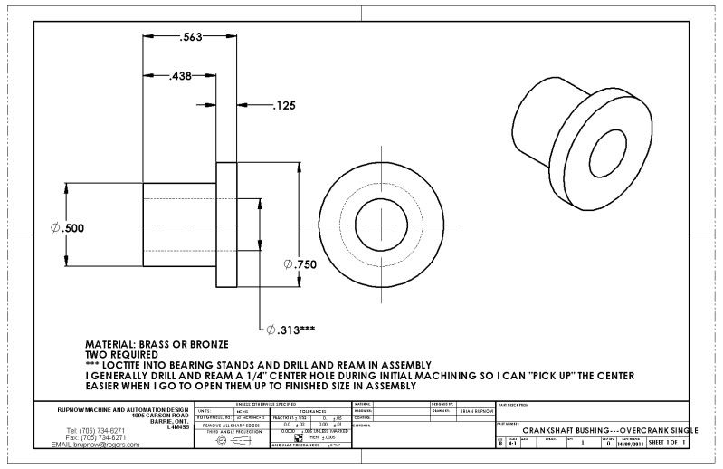
I'll make bushings while I wait for tapered pin information.

- Joined
- Jan 19, 2010
- Messages
- 1,193
- Reaction score
- 41
Brian, FWIW I have made a few built-up crankshafts by reaming a hole .001" undersized (Much cheaper than a tapered reamer) and pressing in a short length of drill rod. Just be careful when pressing not to distort the crank.
I have also made a hole the same size as the pin, with a slight countersink on either side. Then install the pin, it should be a tight fit, and peen the ends over into the countersunk area. Then you can file and sand down the exposed pin and end up with a near seamless joint that should not come loose.
Also, I install the pins perpendicular to the way shown above. I usually go though the crank pin and main shaft with the same pin. The long way I suppose it would be called.
Kel
- Joined
- Dec 2, 2008
- Messages
- 971
- Reaction score
- 9
Brian
Do you think that the tapered pins are really necessary. You are building a steam engine and Aeromotor is talking IC engine. The forces are drastically different. You mentioned split dowel pins. Is that the same as a roll pin or a tension pin? Stews soft nails seem adequate for steam engine and probably look better than roll pins.
Jerry
Jerry--Probably you are right---I don't need the strength of tapered pins. A split dowel pin is a hollow pin with a full length split down one side. They are made of spring steel and are slightly oversize so that they are a "light hammer fit" into a reamed hole. The reason I am persuing this, is that if I buy a tapered reamer and a box of 20 split pins, that will probably do me for the next four single cylinder engines I build, whether they are i.c. or steam. My reasoning is this----if every motor I built was ready to run as soon as I finished assembling it, then it would be a non issue. The connecting rod would supply evenly distributed load to the crank web on each side. Sadly, however, the reality is that thes small engines are generally "tight" when first assembled, and consequently demand that everything get a good soaking in oil and then ran for an hour or so with an electric drill untill everything "frees-up" enough to run on their own power. The power from the electric drill is transmitted from one end of the crankshaft, and consequently puts unequalized torsional loads on the crankshaft. I have had one silver soldered crankshaft fail because of this, during the break-in running. ----Brian
Brian as for drill sizes on the tapered pins, I measure the smallest end of the pin and drill that size. Our tapered pins come in fractional sizes eg 1/16" , 3/32", 1/8" etc and have a 1:48 taper (1:50 on the metric ones)
Having said that on cranks I just drill through with a suitable drill, lightly CSK and then slip a bit of mild steel rod in and pein over the ends, once its filed flush you can't see the pins without looking really hard. Also use the full length bar for teh crank and cut out after pinning/soldering.
J
Groomengineering
Well-Known Member
- Joined
- Aug 2, 2009
- Messages
- 242
- Reaction score
- 3
Brian, the only real advantage to a tapered pin is the ability to remove it easily at a later date, i.e. gear trains, etc. A spring pin should work but might look a little out of place. Nails, drill rod, etc. as Stew and Kel suggested work very well as they are almost invisible when finished.
...And you can't beat a nail for price. ;D
BTW, nice work so far. It's going to be a neat little engine. Thm:
Cheers
Jeff
...And you can't beat a nail for price. ;D
BTW, nice work so far. It's going to be a neat little engine. Thm:
Cheers
Jeff
The bushings are finished and installed. Since I want to continue the momentum of this build, and not wait for a week to get in tapered pins, I will just go back to my original plan and use 3/32 dia. cold rolled rod for my pins instead of the split dowel pins. If it all flys apart at some point in the future, I will remake it with tapered pins then. At the speed and power this engine will develop, I doubt that any buildings will be destroyed or lives lost if the crankshaft does "Come a cropper!!!"
tel
Well-Known Member
- Joined
- Feb 8, 2008
- Messages
- 3,293
- Reaction score
- 45
I never bother with taper pins either - as Jeff said, you can work wonders with a handful of nails and the appropriate drill. What I do do, however, is lightly countersink the ends of the holes and gently rivet the pin ends down into 'em before filing flush. A cut-off wheel in Mr Dremel is your friend!
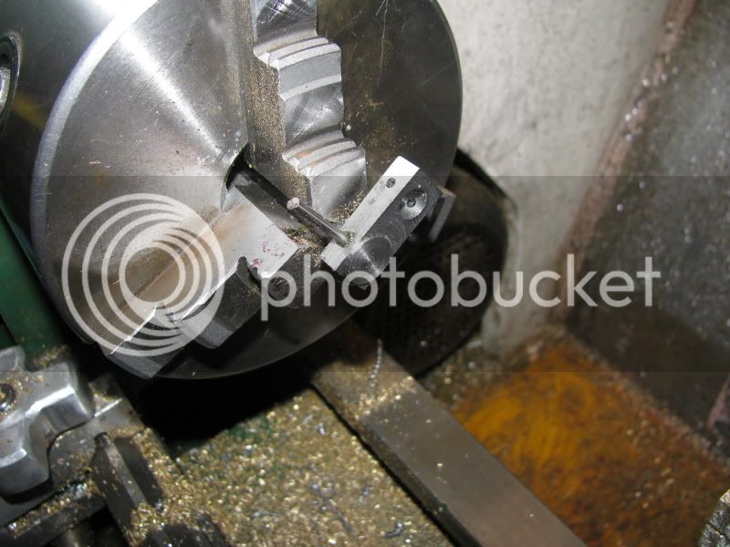
Here is a "How I did it" shot---Turning the boss on the crankshaft "throw" (also called the web". I have drilled and reamed the 3/32" holes which will eventually pin the throw to the crankshaft, and also a "throw away" peice of 5/16" rod about 1 1/2" long. The long peice of 3/32 dia. rod has a dab of Loctite on it to hold it from falling out, and the 5/16" rod is gripped in the 3 jaw chuck. I know there are other ways to do this, but this method seems to be working well---so far. Tomorrow morning I will heat it up a bit, remove both the 3/32 rod and the 5/16" rod, machine the other "throw" the same way, and then be ready to set them up on the final 5/16" peices of rod that form the actual crankshaft, then cross drill, pin, and Loctite.

I guess its time for some valvey type drawings--
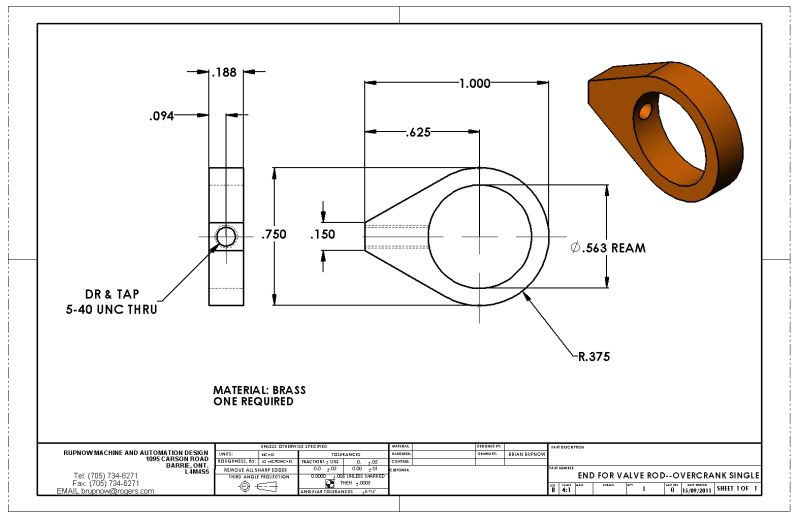
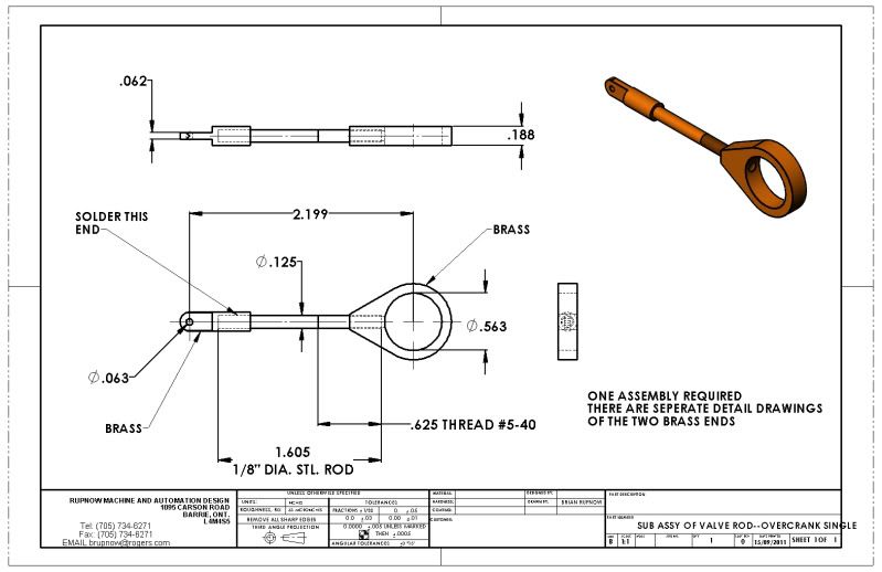
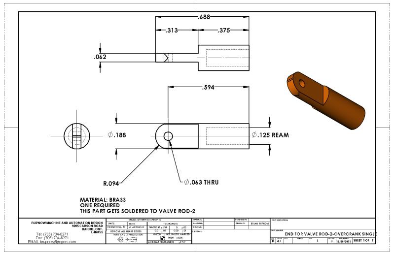
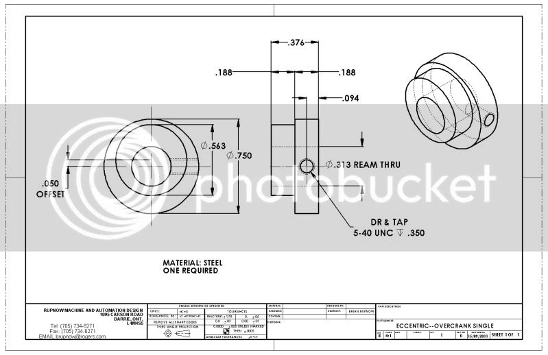


- Joined
- Aug 25, 2007
- Messages
- 3,890
- Reaction score
- 715
Brian Rupnow said:The bushings are finished and installed. Since I want to continue the momentum of this build, and not wait for a week to get in tapered pins, I will just go back to my original plan and use 3/32 dia. cold rolled rod for my pins instead of the split dowel pins. If it all flys apart at some point in the future, I will remake it with tapered pins then. At the speed and power this engine will develop, I doubt that any buildings will be destroyed or lives lost if the crankshaft does "Come a cropper!!!"
Brian, have you considered roll pins, sometimes called spring pins?
Chuck
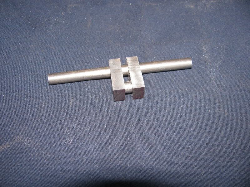
Yes, but the deed is done now. The crank is built and setting on the corner of by desk, looking like the cross bred son of a crankshaft and the green blob from planet X. I have found that I am as messy with Loctite as I am with silver solder. Hopefully though, the Loctite will be easier to clean up!!! I used 3/32" cold rolled stl. rod for my lockpins.
Similar threads
- Replies
- 95
- Views
- 14K
- Replies
- 11
- Views
- 1K
- Replies
- 413
- Views
- 68K


![Learning AutoCAD Civil 3D 2014 [Online Code]](https://m.media-amazon.com/images/I/51F3yi9fokL._SL500_.jpg)


