Overcrank Single Cylinder Engine

Home Model Engine Machinist Forum

Help Support Home Model Engine Machinist Forum:

This site may earn a commission from merchant affiliate links, including eBay, Amazon, and others.
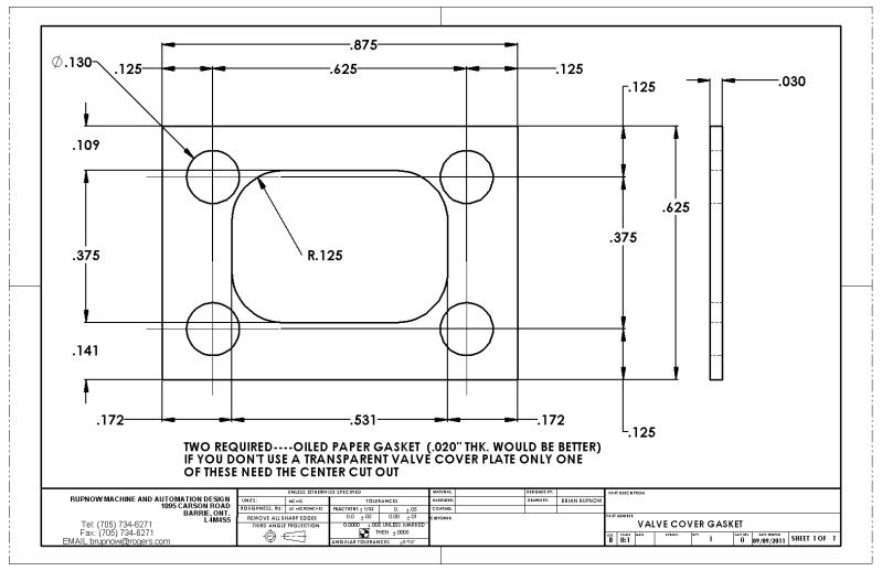
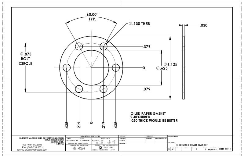
Today we are building gaskets. The material I have on hand is about 0.030" thick, but as I noted on the drawings, 0.020" thick material would probably be better. These small engines are very sensitive to air loss, so you really do need these gaskets.
CYLINDERHEADGASKET.jpg

VALVECOVERGASKET.jpg
 
Brian have you thought of using a bit of clear silicon to seal the cover, I use the liquid gasket quite a bit on smaller engines saves having to torque down small fixings too tight trying to compress a gasket.

J
 
Jason---its not that critical that I see the valve working. I had already replaced it with a peice of brass by the time you posted. I may have to open up the slots in the slide valve a tiny bit with a file, in order to get it to lay truly flat against the steel slide plate. Right now its working, but I have way more power on extend than I do on retract, and air is escaping out the stack at mid travel when it should be closed.
 
Something possibly worth mentioning, esp. with running on steam, is not to block the admission ports with the spigot of the cylinder heads. For my loco build, I have been advised to mill a small notch in the spigot to give free access to the steam admission. It may still be advisable even on air to allow better operation at lower pressure.
 
Brian Rupnow said:
Right now its working, but I have way more power on extend than I do on retract,

Are you loosing air around the piston rod, as you don't seem to have any form of gland to seal the rod.

Yes you will need a little play on the slidevalve to allow it to find its own level over the portface. And if on steam a bit of lift to allow any condensate out of the cyl and prevent hydralic locking.

J
 
On these small engines, which I run on compressed air, there isn't really a need for a packing nut and gland where the rod exits. There is VERY little air lost there, and the added friction is detrimental to the operation of the engine.
 
I lay in bed last night, thinking about the design of this engine. (I do this quite often at the end of the day, reviewing what I have done and what my next steps will be.) My train of thought was---What actually stops or limits the travel of the piston in the cylinder? Its not the length of the cylinder barrel,---Its the throw of the crankshaft. Because--At its maximum limits of travel, there is in theory, a 1/32" gap between the end of the piston and the cap on each end of the cylinder.----and thats not even taking into account the thickness of the gasket under each cylinder cap. Now the overcrank mechanism is connected solidly to the end of the piston rod. The cylinder is bolted in place, and the crankshaft bearing is fixed in place. If everything is not located with "dead nuts" accuracy, and the connecting rod is a fixed dimension between ends, then how does one adjust things to get that piston centered exactly in the cylinder the way it should be. I can not (Or at least don't want to) adjust the crankshaft position.---So---I must be able to adjust the position of the cylinder in relationship to the crankshaft! Sure enough, I opend Sbwharts drawing package, and that is exactly what he had done.---Put slots in the baseplate to allow him to move the cylinder closer to or farther from the crankshaft. I have any number of things which I could build next, but the danger of that now finished cylinder getting bumped off my bench onto the floor is too great. I think I will tackle the main backbone of this thing, the main spine which everything sets on, and the baseplate.
 
This is one of those cases where the drawing usually says "check length on assembly" It would be worth making the piston rod a little longer and then finally adjusting once the engine is built up. As yours is alread loctited & punched you may need to skim one side of the piston to make adjustments as you can't add to the length of the rod.

At least you don't have the problem we get on the traction engines of the boiler length increasing as things warm up, what may be nicely balanced valve movements and end clearances when cold go out the window once there is a fire under it :)

J
 
A question for all the slide valve gurus out there. I am still messing about with the slide valve and cylinder that I showed in the previous video. It seems that when I shift the valve in one direction, I get lots of force to extend the piston rod. However, when I shift the valve thru its correct travel (which is only 0.100" on this engine), the retraction force of the piston rod is pretty wimpy and weak. I have tried numerous different valve positions, I have lapped the face of the valve plate and the sliding surface of the valve, and it doesn't seem to make a great deal of difference. Strong push on extend, weak retract. This puzzled me to such an extent that I switched my new valve gear with the valve gear on the Elmers 33 that I built two years ago (its the exact same) and the Elmers 33 runs fine with my new valve gear on it. I then put the complete valve set up from elmers engine on my new cylinder, and it still acts the same. Strong extend, weak retract. Common sense and science tells me that the force should be the same in both directions, but it isn't!!! Can anybody offer a reason for what I am seeing?---Brian
 
You are aware, I trust, that the effective area of the piston on the retract stroke is reduced by the area of the piston rod. The forces in the two directions can never be equal.

However, I doubt that this effect is enough to account for what you're experiencing. Have you checked for spooge in the steam channel from the valve to the cylinder? Have you done the soapy water test to detect leaks from the cylinder cover on the piston rod side?
 
Marv you beat me to it.
The return will be affected by the surface area lost to the connecting rod.
 
You would have noticed a leak so that's out. A reduction or oclusion of the steam (air) passage is
all that comes to mind. Swapping out the valve gear eliminates a pressure bleed to the extending side.
Exhaust port not fully open and cylinder retaining pressure? Hope you get it sorted.

Regards,
Mike
 
Yes, I have tried all the suggested tricks. I know that the area of the rod must be subtracted when doing force calculations on the return stroke, but in this case the rod is too small to account for such a large difference. I have done the soapy water test, the gunk in the passage test, all the tests which make sense. I have spent a day screwing about with this, but have decided to forge onward and sort it out at a later date if necessary. Tests show the same effect on my Elmers#33 and it runs fine, so I'm not going to worry about it right now.---Damn the torpedoes!!! On to the next part!!!
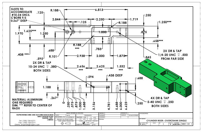
CYLINDERRISER--OVERCRANKSINGLE-1.jpg
 
Hi Brian

The engine is building up nicely.

I opend Sbwharts drawing package, and that is exactly what he had done.---Put slots in the baseplate to allow him to move the cylinder closer to or farther from the crankshaft.

Sorry I didn't flag up more in my build log it was just one of those things that I figured out and built into the design without giving any explination.

Strong push on extend, weak retract

Could the fact you have no seal arround the valve rod contribute to this, when its pushing the air is going into the side of the piston with no leak, when its retracting its going into the side with no seal, so its losing air and push.

Thats if I'm understanding the valve rod sealing correctly.

Hope this helps

Stew

I suspect that this may be part of the problem, made worse by ...

Exhaust port not fully open and cylinder retaining pressure? Hope you get it sorted.

Regards,
Mike

... owing to the, IMHO, inadequate exhaust porting and passages.
 
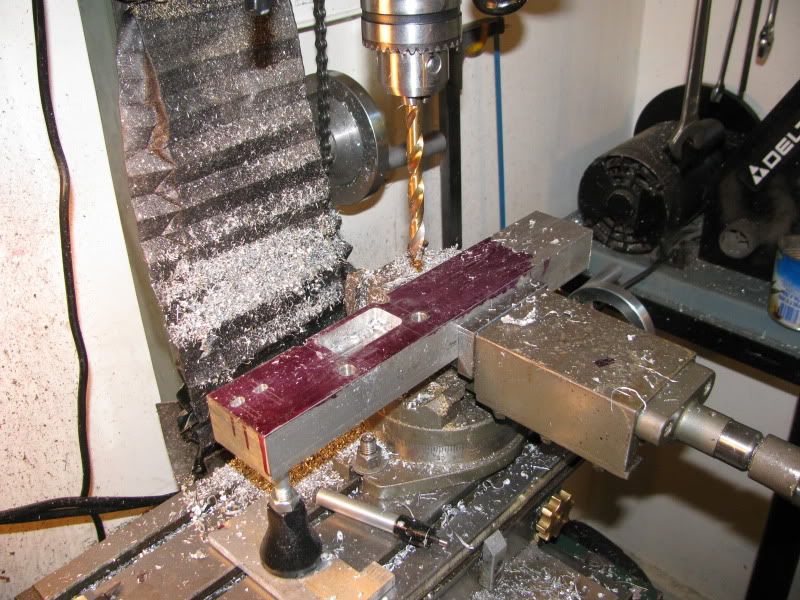
And this is how I spent my afternoon!!! Whatever is happening with the valving will get sorted out "eventually". Really, it is losing very very little pressure where the piston rod passes thru the cylinder end cap. Right now, its "On with the build".
CYLINDERRISERINPROCESS001.jpg
 
;D Thm:

Truth is, you might hardly be able to tell the difference with the engine complete and running!
 
My guess would be what others have said, there is a misalignment in the valve edges and the port edges causing a restriction.
The misalignment could be from the valve not making full travel in one direction perhaps due to being limited in its travel by the small steam chest.

The steam chest, ports and passages seem to be about 1/2 too small for this engine.
When using such a tiny valve and ports, it would be very difficult to get good alignment.

The thing about steam engines is that almost any arrangement of valve and ports will run any engine under no load. The problems show up when a load is applied.

Since almost nobody every puts a load on a small steam engine, then the valve and ports almost always get neglected and don't function as well as they could.

My guess only.

Pat J
 
GOOD NEWS THIS MORNING!!!! I came down to my shop, took both end caps of the cylinder, and hooked the airline to my valve. I cycled the valve in both directions, and air flowed out, full blast at each appropriate end when the valve was shifted. ???? I then reversed the caps on the cylinder, and when the valve shifted, the piston rod went roaring in and out like gangbusters.???? What the heck------So, I reversed the end caps again, back to where they should have been and it still worked great!!!! Must have been a peice of "spooge" (I think thats Marv's word, I like it) in the air passage drilled thru the cylinder to the rod end and it blew out when I had both end caps off. I feel much better about the world now!!!----Brian
 

Latest posts

Back
Top