- Joined
- Apr 3, 2017
- Messages
- 232
- Reaction score
- 120
Hi HMEM,
I wanted to run something by all you knowledgeable sorts out there. I have just completed a Webster engine and toying with the idea of having a go at designing an amateur workshop-friendly copy of the popular OS FS120 4-stroke glow engine (un-pumped).
https://www.osengines.com/engines-airplane/osmg0935/index.html
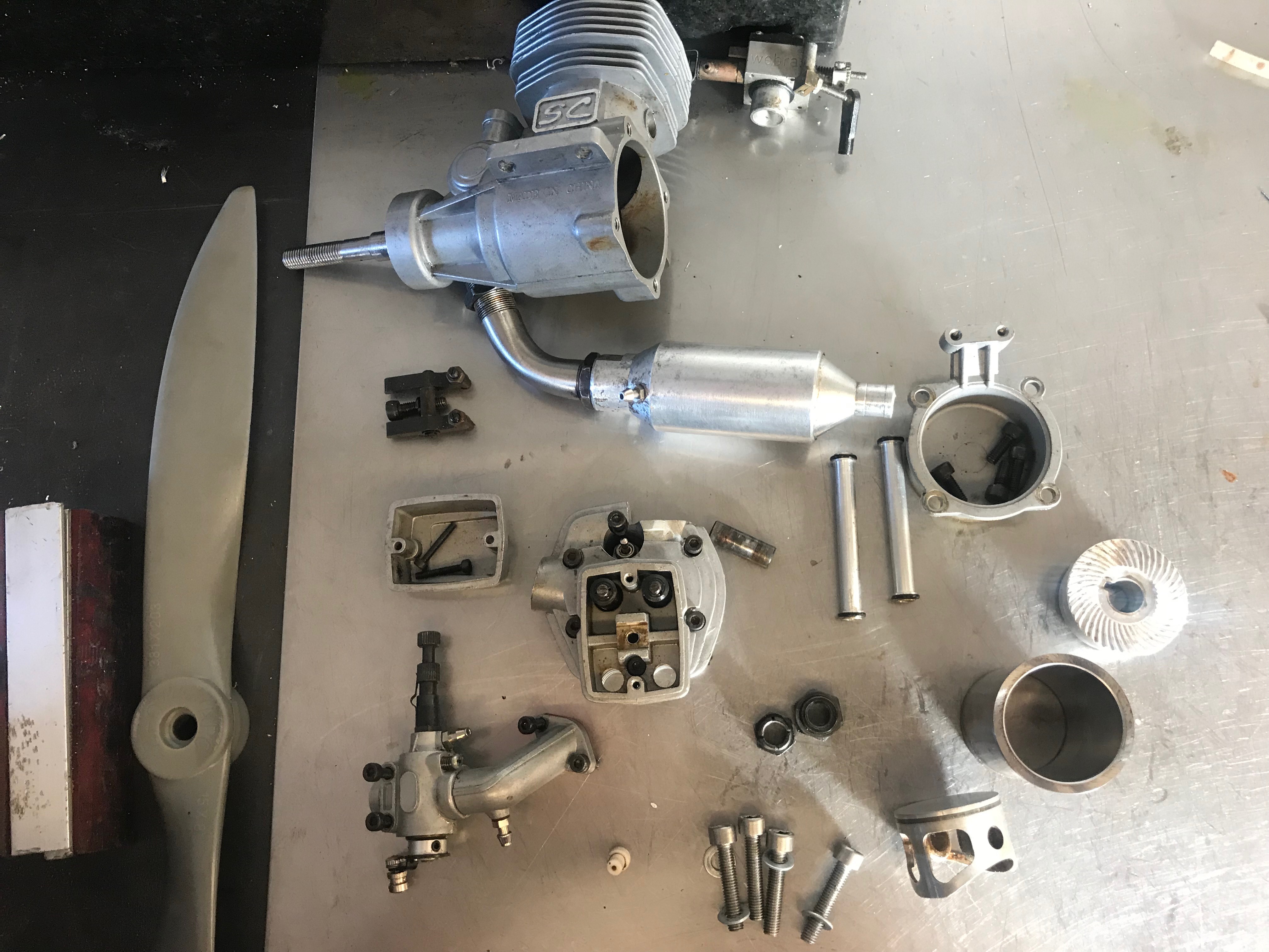
I got my hands on one (actually the Chinese copy Super Custom SC) from fleabay and it runs goes like crazy. Starts firs flick and turns a large propeller with enough power to pull over a workmate (don't ask me how I know).
Inside:
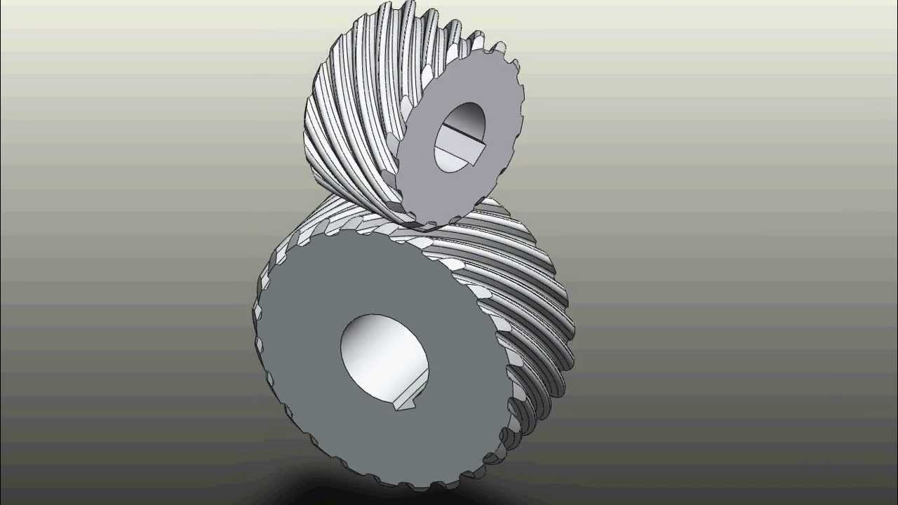
My thought is to instead use an inline cam gear/camshaft like the Saitos
https://alshobbies.co.uk/saito-engines
which could be done simply-ish with an involute gear cutter.
I have seen some similar amateur designs but have not been happy with using a timing belt to drive the camshaft as it would limit the practical application of the engine beyond stationary engine.
The purpose of this project for me is both honing the machining skills but also (FINALLY) take the plunge and learn a CAD package or die trying. I've not really spent enough time with Autocad Fusion360 to get past the tearing hair out phase.
Sooo.. the question to this forum is whether there are any other such copies already out there (I couldnt find any) and, in your opinion, how feasible this would be/where the main challenges would be (gears, piston rings I've already just about figured out)
I wanted to run something by all you knowledgeable sorts out there. I have just completed a Webster engine and toying with the idea of having a go at designing an amateur workshop-friendly copy of the popular OS FS120 4-stroke glow engine (un-pumped).
https://www.osengines.com/engines-airplane/osmg0935/index.html
I got my hands on one (actually the Chinese copy Super Custom SC) from fleabay and it runs goes like crazy. Starts firs flick and turns a large propeller with enough power to pull over a workmate (don't ask me how I know).
Inside:
- Ringed piston so no taper lapping etc required (I used cast iron piston rings on my Webster with great success)
- Steel liner
- 1-piece crankshaft (that could be made in 2 to save on swarf)
- Pushrod OHV design (cant see how the rockers get enough lubrication but its a design that seems to have been around for years so obviously works OK)
- Lubrication from 2-stroke oil blowby in the crank case
My thought is to instead use an inline cam gear/camshaft like the Saitos
https://alshobbies.co.uk/saito-engines
which could be done simply-ish with an involute gear cutter.
I have seen some similar amateur designs but have not been happy with using a timing belt to drive the camshaft as it would limit the practical application of the engine beyond stationary engine.
The purpose of this project for me is both honing the machining skills but also (FINALLY) take the plunge and learn a CAD package or die trying. I've not really spent enough time with Autocad Fusion360 to get past the tearing hair out phase.
Sooo.. the question to this forum is whether there are any other such copies already out there (I couldnt find any) and, in your opinion, how feasible this would be/where the main challenges would be (gears, piston rings I've already just about figured out)


![DreamPlan Home Design and Landscaping Software Free for Windows [PC Download]](https://m.media-amazon.com/images/I/51kvZH2dVLL._SL500_.jpg)


