You are using an out of date browser. It may not display this or other websites correctly.
You should upgrade or use an alternative browser.
You should upgrade or use an alternative browser.
OS FS120 or Saito copy. Bar stock glow engine.
- Thread starter pat_pending
- Start date

Help Support Home Model Engine Machinist Forum:
This site may earn a commission from merchant affiliate
links, including eBay, Amazon, and others.
- Joined
- Apr 3, 2017
- Messages
- 233
- Reaction score
- 125
Hi, thanks for all the helpful replies. I have decided its just too much trouble to try making these helical gears. I'm going to use standard spur gears on this design and have them up front like the Saitos. Doesn't look quite as sleek but I think will increase the chances of success greatly given my machining skills (or lack thereof!). I have some 32dp cutters lying around from the Webster build and think a 25T/50T will work on a 10mm crankshaft with a 4mm keyway. 50T will be quite large but will see what it looks like on CAD rendering.
As a newcomer to this forum, is this the right place to blog the design/build? I will hopefully be able to get some CAD time this weekend and get going.
As a newcomer to this forum, is this the right place to blog the design/build? I will hopefully be able to get some CAD time this weekend and get going.
- Joined
- Oct 1, 2010
- Messages
- 1,418
- Reaction score
- 443
pat_pending,
I think perhaps "A Work in Progress" may be a good place for your design/build thread
--ShopShoe
I think perhaps "A Work in Progress" may be a good place for your design/build thread
--ShopShoe
Cogsy
Well-Known Member
I've moved it over for you so you can keep posting in this thread - that way you don't lose the narrative so far.
- Joined
- Apr 3, 2017
- Messages
- 233
- Reaction score
- 125
ThanksI've moved it over for you so you can keep posting in this thread - that way you don't lose the narrative so far.
- Joined
- Apr 3, 2017
- Messages
- 233
- Reaction score
- 125
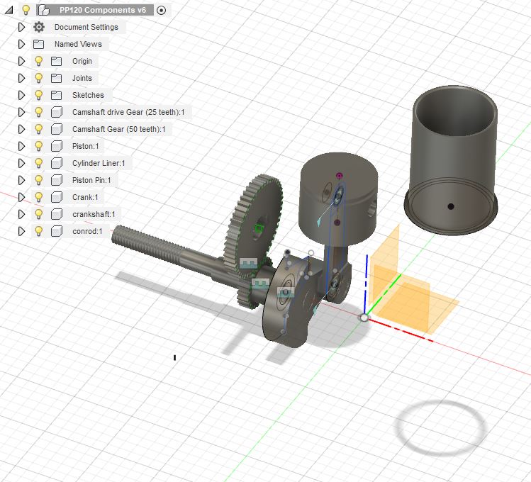
Hi, managed to spend a bit of time thinking about the build over the weekend (and wrestling with CAD  ).
).
Here's where I got to so far

I think the challenge will be designing a crank case to fit all this inside that still looks OK and more importantly, if the camshaft is up front, still allows adequate cooling for the cylinder. I have seen some designs with the cams at the back for this reason however making a split crankshaft doesn't appeal to me.
I will hopefully have some more time to fiddle soon!
PS: Yes I know the cylinder liner is upside down!
Here's where I got to so far

- Crank and counterweight, piston, sleeve, conrod measured off the OS FS120. The counterweight will be a little bit light as the piston will be heavier so may tweak it.
- Crankshaft 15mm at the main bearing journal and down to 10 where the crankshaft drive gear sits. This size limited the size of the drive gear to minimum size of 25 teeth if I want to leave some space for a keyway.
- Spur gears are 32TPI to hopefully be able to leverage the #3 and #5 involute gear cutters I have available from the Webster build.
- I have a camshaft modelled up also using the profiles from the webster for now. Will revisit to see if I want Something more aggressive.
I think the challenge will be designing a crank case to fit all this inside that still looks OK and more importantly, if the camshaft is up front, still allows adequate cooling for the cylinder. I have seen some designs with the cams at the back for this reason however making a split crankshaft doesn't appeal to me.
I will hopefully have some more time to fiddle soon!
PS: Yes I know the cylinder liner is upside down!
Last edited:

$99.99
AHS Outdoor Wood Boiler Yearly Maintenance Kit with Water Treatment - ProTech 300 & Test Kit
Alternative Heating & Supplies

$37.38
$49.99
Becker CAD 12 3D - professional CAD software for 2D + 3D design and modelling - for 3 PCs - 100% compatible with AutoCAD
momox Shop

$45.99
Sunnytech Mini Hot Air Stirling Engine Motor Model Educational Toy Kits Electricity HA001
stirlingtechonline
![DreamPlan Home Design and Landscaping Software Free for Windows [PC Download]](https://m.media-amazon.com/images/I/51kvZH2dVLL._SL500_.jpg)
$0.00
DreamPlan Home Design and Landscaping Software Free for Windows [PC Download]
Amazon.com Services LLC

$599.00
$649.00
FoxAlien Masuter Pro CNC Router Machine, Upgraded 3-Axis Engraving All-Metal Milling Machine for Wood Acrylic MDF Nylon Carving Cutting
FoxAlien Official

$19.15
$29.95
Competition Engine Building: Advanced Engine Design and Assembly Techniques (Pro Series)
MBC Inc.

$49.95
$55.99
DjuiinoStar Hot Air Stirling Engine Assembly Kit: Spend 30 Minutes to Build Your Own Stirling Engine
djuiinostar

$26.89
$34.99
Peachtree Woodworking Supply Bowl Sander Tool Kit w/Dual Bearing Head & Hardwood Handle, 42 Pieces Wood Sander Set, 2 Hook & Loop Sanding Disc Sandpaper Assortment, 1/4 Mandrel Bowl Sander
Peachtree Woodworking Supply Inc
Hi,
Just to add my views why not use the Laser engine type valve gear mounted on the rear or the engine crankcase and driven from the crankpin they use straight cut gears that may be easier for you (see picture) alternatively I built an 60 size engine using commercially available skew gears the driver was steel and the driven brass this allowed me to dowel the cam lobes either side of the brass gear.
Regards,
Peter
Attachments
- Joined
- Apr 3, 2017
- Messages
- 233
- Reaction score
- 125
That's a good approach. Like it. Ill have a look around for a 2-part/sided counter weighted crankhaft design tonight (there must be something on model engine news).Hi,
Just to add my views why not use the Laser engine type valve gear mounted on the rear or the engine crankcase and driven from the crankpin they use straight cut gears that may be easier for you (see picture) alternatively I built an 60 size engine using commercially available skew gears the driver was steel and the driven brass this allowed me to dowel the cam lobes either side of the brass gear.
Regards,
Peter
Thanks for posting
- Joined
- Apr 3, 2017
- Messages
- 233
- Reaction score
- 125
Hi Andrew, do you know what the skew angle of the driving (crankshaft) and driven (camshaft) gear is on your setup please? I have heard any angle combination works provided that the sum is 90deg for perpendicular screw gears. I heard 60/30 ratio but I haven't found the formula to calculate the gear ratio yet therefore I don't know which one should be which. I have got my hands on some CAD plugins to generate the gears so may have a fiddle with a 3D-printed prototype.I got these from HK, NGH engine parts, a little machining and I have the cam and gear set.
Cheers
Andrew
Thanks,
Patrick
Patrick, I don't know what the angles are, Will get a measurement of the gears later today.
Cheers
Andrew
Cheers
Andrew
Hi Andrew,That's a good approach. Like it. Ill have a look around for a 2-part/sided counter weighted crankhaft design tonight (there must be something on model engine news).
Thanks for posting
I finally remembered where I got my gears from this site is worth a look http://www.hpcgears.com/
Regards,
Peter
Peter,Hi Andrew,
I finally remembered where I got my gears from this site is worth a look http://www.hpcgears.com/
Regards,
Peter
Thank you for the site, Will be able to look through for gears.
Cheers
Andrew
- Joined
- Apr 3, 2017
- Messages
- 233
- Reaction score
- 125
Legend! thanks for measuring. So 30 on the crankshaft(driving) gear, 60 on the camshaft(driven) gear. Same PA/module. 90deg drive should work. I hope to get tinkering on a prototype gear this weekend.Patrick, The gears are a 60/30 ratio as good as I measured. Hope this helps.
Cheers
Andrew
- Joined
- Apr 3, 2017
- Messages
- 233
- Reaction score
- 125
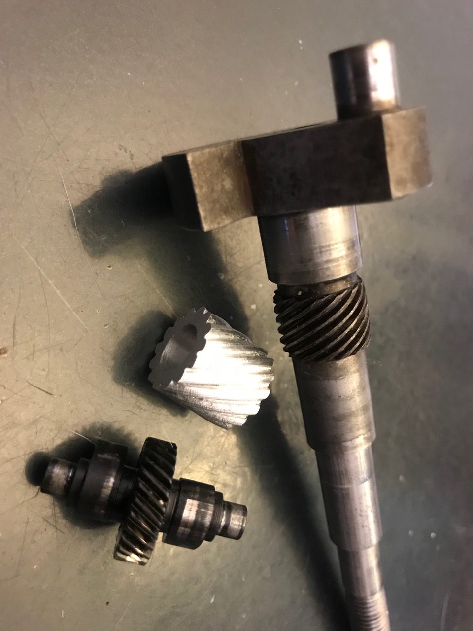
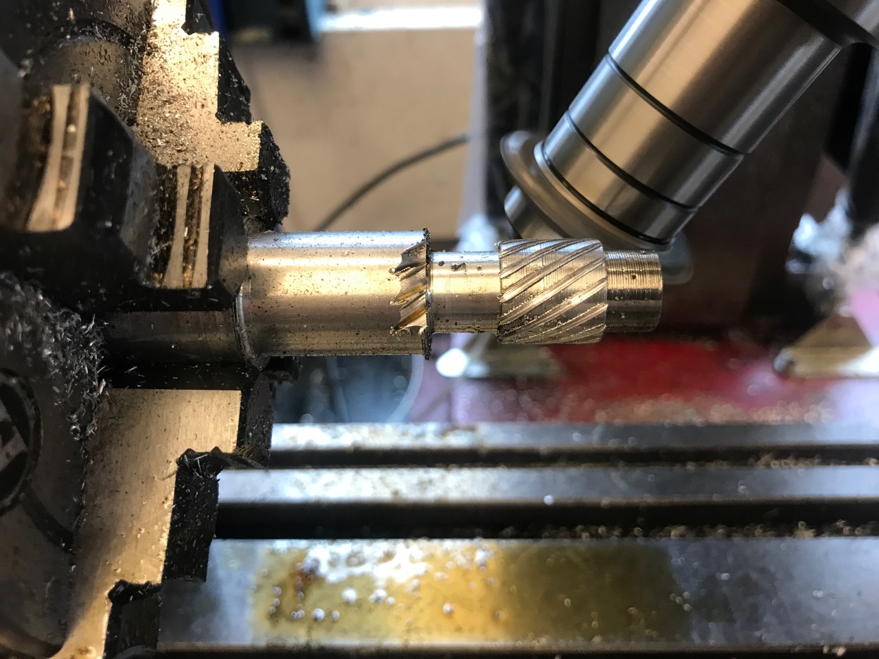
OK so a *bit* of progress today. After reading a load of articles during the week and trying to get my head around the maths, I ended up going for Gearotic: http://www.gearotic.com.
I had a few dead ends with CAD (both Blender and Fusion 360). Gearotic seemed to do the trick.
I had a play with the 60/30 helix angles and tried to work out the module from the OD and the number of teeth. I then used the 4-axis CAM plugin to generate a GCODE tool path for a vertical mill. I flipped the Z axis for the Y axis in a text editor and it seemed to work (ish). Anyway, it looks nothing like the gear I'm trying to make but i have a workflow and fixture set up on the mill so experimenting with different options won't be quite so time-consuming.


I had a few dead ends with CAD (both Blender and Fusion 360). Gearotic seemed to do the trick.
I had a play with the 60/30 helix angles and tried to work out the module from the OD and the number of teeth. I then used the 4-axis CAM plugin to generate a GCODE tool path for a vertical mill. I flipped the Z axis for the Y axis in a text editor and it seemed to work (ish). Anyway, it looks nothing like the gear I'm trying to make


Similar threads
- Replies
- 11
- Views
- 1K


![20180802_164018[1].jpg](https://cdn.imagearchive.com/homemodelenginemachinist/data/attachments/56/56983-07e32fca6de77e223ab3890401ed634e.jpg)
![20180802_164025[1].jpg](https://cdn.imagearchive.com/homemodelenginemachinist/data/attachments/56/56984-df1706994fa3f71886a6243308880865.jpg)
![20180802_164040[1].jpg](https://cdn.imagearchive.com/homemodelenginemachinist/data/attachments/56/56985-7fb87d90f7d3ec255f06395a0df22232.jpg)


![MeshMagic 3D Free 3D Modeling Software [Download]](https://m.media-amazon.com/images/I/B1U+p8ewjGS._SL500_.png)


![20180809_101139[1].jpg](https://cdn.imagearchive.com/homemodelenginemachinist/data/attachments/57/57126-f6ae1552f183a13047705e2183ca579a.jpg)
![20180809_101313[1].jpg](https://cdn.imagearchive.com/homemodelenginemachinist/data/attachments/57/57127-cca77163268282bf83f2d6fd03f2765d.jpg)