The cam needs to be quite a different shape to the usual IC engine profile to get that quick open and close together with dwell. Also depends if the "high" part of the cam is closing or opening the shutter
You are using an out of date browser. It may not display this or other websites correctly.
You should upgrade or use an alternative browser.
You should upgrade or use an alternative browser.
My next build--A cross beam vacuum engine
- Thread starter Brian Rupnow
- Start date

Help Support Home Model Engine Machinist Forum:
This site may earn a commission from merchant affiliate
links, including eBay, Amazon, and others.
Alternatively, a long stroke valve, with a slot that passes the inlet port, and continues to slide staying OPEN past the port as the eccentric goes over that part of the stroke until it returns to close the port.
Is that simple enough?
K2
Is that simple enough?
K2
Yes, exactly.Sid, sounds like a cam action is more appropriate han a circular eccentric?
Jason, your slotted lever is almost exactly like mine for the water feed pump on my boat! Great Minds...? n all that? - Or just some understanding of geometry...
K2
You want to get all the flame you can in the cylinder, then the port needs to shut off and seal for the hot air to meet the cooler cylinder, form a vacuum and have atmospheric pressure push the piston back up, then the valve snaps open again to start the cycle over.
Sid
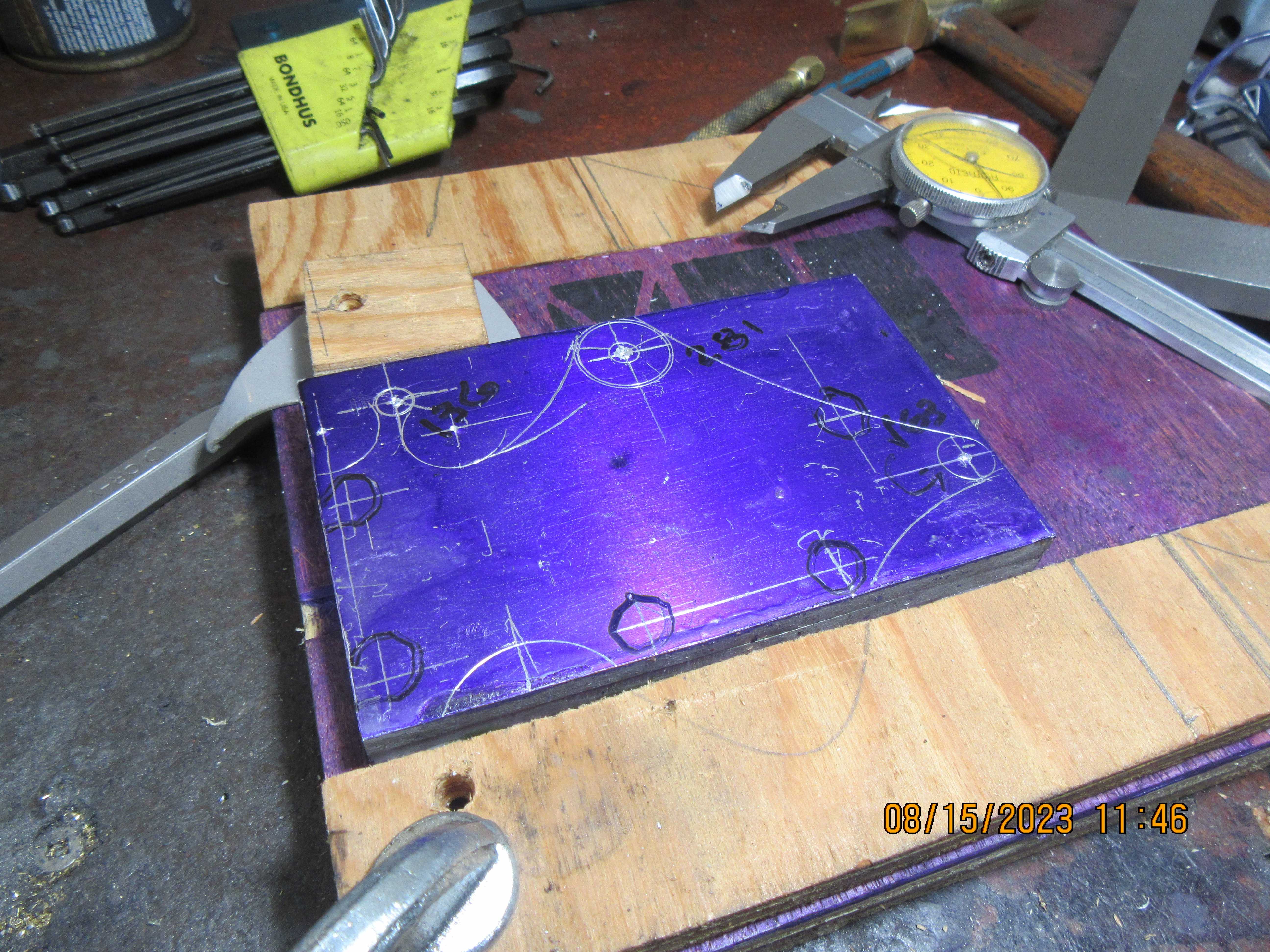
I began laying out the flame sucker sideplate this morning. The two aluminum sideplates are Loctited together then epoxied to the plywood backing plate. This layout shows all of the hole centers and external cuts but not any of the internal cut-outs. This afternoon I will lay out the internal cut outs.

I guess you cook it all after cutting to separate the side plates from the plywood? - I.E. the plywood is just temporary support during cutting by bandsaw?... - I am learning...
K2
K2
Probably don't want to cut the plywood away as it provides a location for all the various arcs that form the shape. Locate the ctr of each arc on the rotary table and mill the whole shape without touching a bandsaw.

$17.65
$18.99
Product-Led SEO: The Why Behind Building Your Organic Growth Strategy
The Quality Books
![DreamPlan Home Design and Landscaping Software Free for Windows [PC Download]](https://m.media-amazon.com/images/I/51kvZH2dVLL._SL500_.jpg)
$0.00
DreamPlan Home Design and Landscaping Software Free for Windows [PC Download]
Amazon.com Services LLC

$94.99
$109.99
AHS Woodmaster 4400 Maintenance Kit for Outdoor Wood Boiler Treatment
Alternative Heating & Supplies

$89.99
Outdoor Wood Boiler Water Treatment Rust Inhibitor- AmTech 300 & Test Kit
Alternative Heating & Supplies

$39.99
$49.99
Sunnytech Low Temperature Stirling Engine Motor Steam Heat Education Model Toy Kit For mechanical skills (LT001)
stirlingtechonline

$37.82
$49.99
Becker CAD 12 3D - professional CAD software for 2D + 3D design and modelling - for 3 PCs - 100% compatible with AutoCAD
momox Shop

$99.99
AHS Outdoor Wood Boiler Yearly Maintenance Kit with Water Treatment - ProTech 300 & Test Kit
Alternative Heating & Supplies

$24.99
$27.99
HOZLY 5PCS/Lot ISO30 Tool Holder Clamp Flame Proof Rubber Claw CNC Machines Automatic Tool Changer
HOZLY
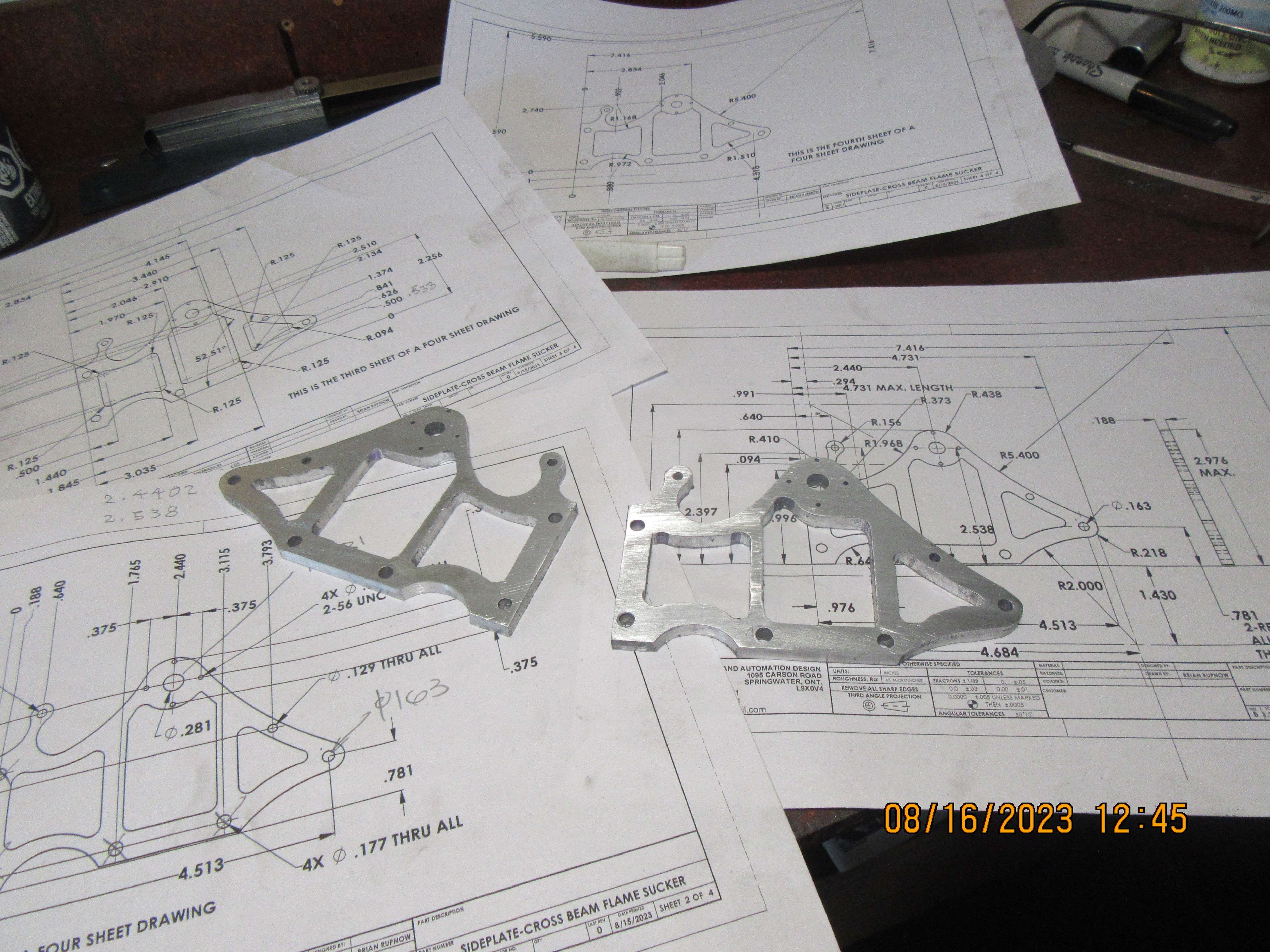
This morning I machined the engine sideplates. If you are wondering why that one internal rib is so much thinner than the other one---Just as I was machining that feature, there was a huge meteor strike just outside my machine shop window. The impact was so great it threw my milling machine off axis, and I didn't realize until the part was finished that had happened. I have to go now and move my lawn ornaments to higher ground before the tsunami gets here.

Brian,
It looks great as always. Following along.
Cheers
Andrew
It looks great as always. Following along.
Cheers
Andrew
Steamchick--the plywood was there just to provide a center for my compass to make some of the large arcs. You really can't depend on Loctite or epoxy to hold the parts on the plywood while you are machining them. After the laying out was done, the parts were broken loose from the plywood and held in my machinist's vice for machining.
Thanks Brian. - If the meteorite landed on your garden, then it becomes your property.... sell it on ebay! It may be full of valuable minerals? (Ha! Ha!).
I understand your worries about Tsunamis.... they happen all the time in Ontario... - or so I am told? (Never believe all you read on the web! - Sometimes it is true!).

I understand your worries about Tsunamis.... they happen all the time in Ontario... - or so I am told? (Never believe all you read on the web! - Sometimes it is true!).
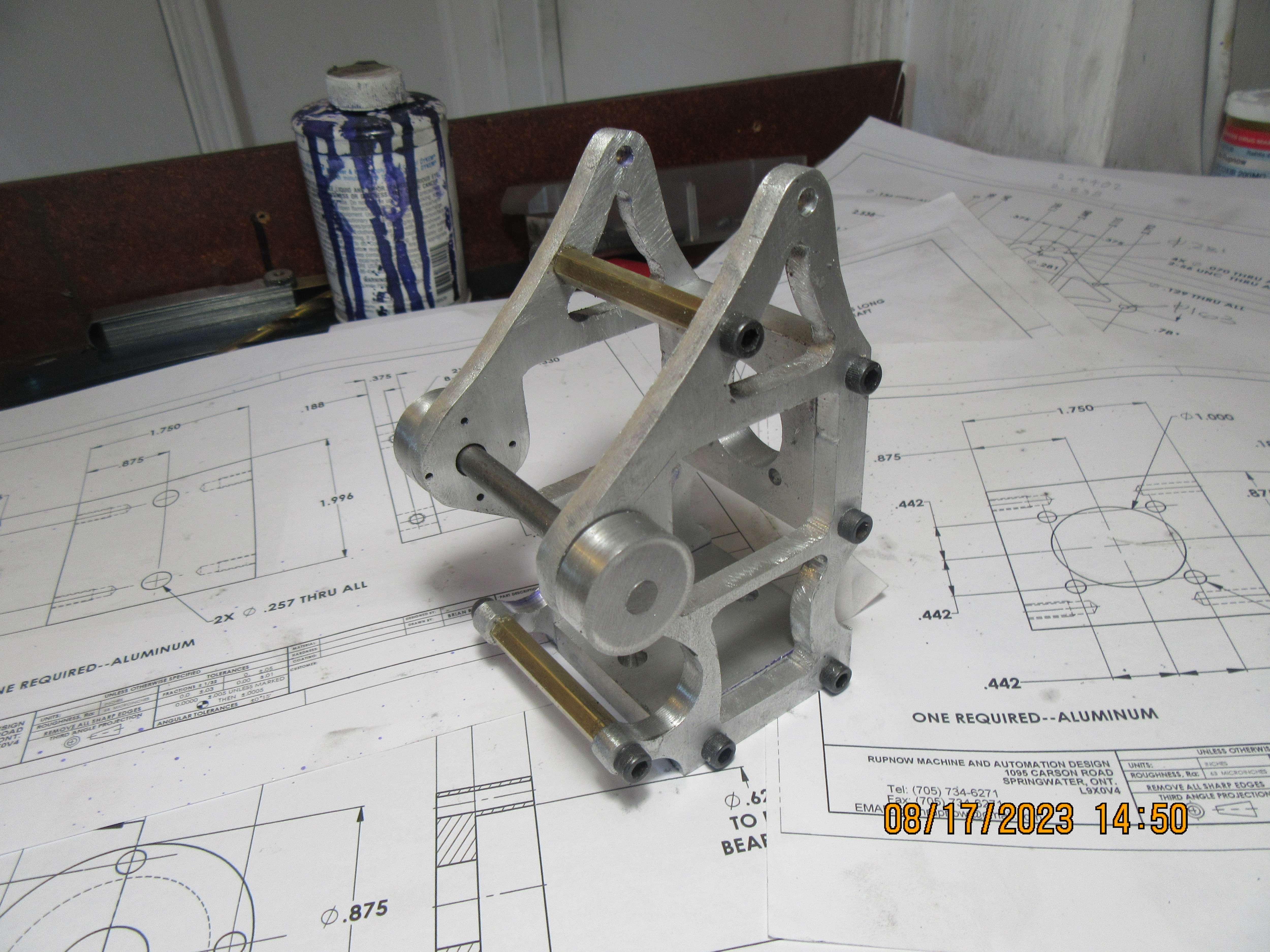
No meteors today. It's 3:11 now, and I've worked since about 10:00 this morning. The base plate and the plate which holds the cylinder in place are finished. The spreader bars are finished, and the ball bearing housings are finished. I could go ahead and make the cylinder today, but right now I've got to go and grab something to eat. I didn't realize how dirty everything on the engine was until after I took the picture.
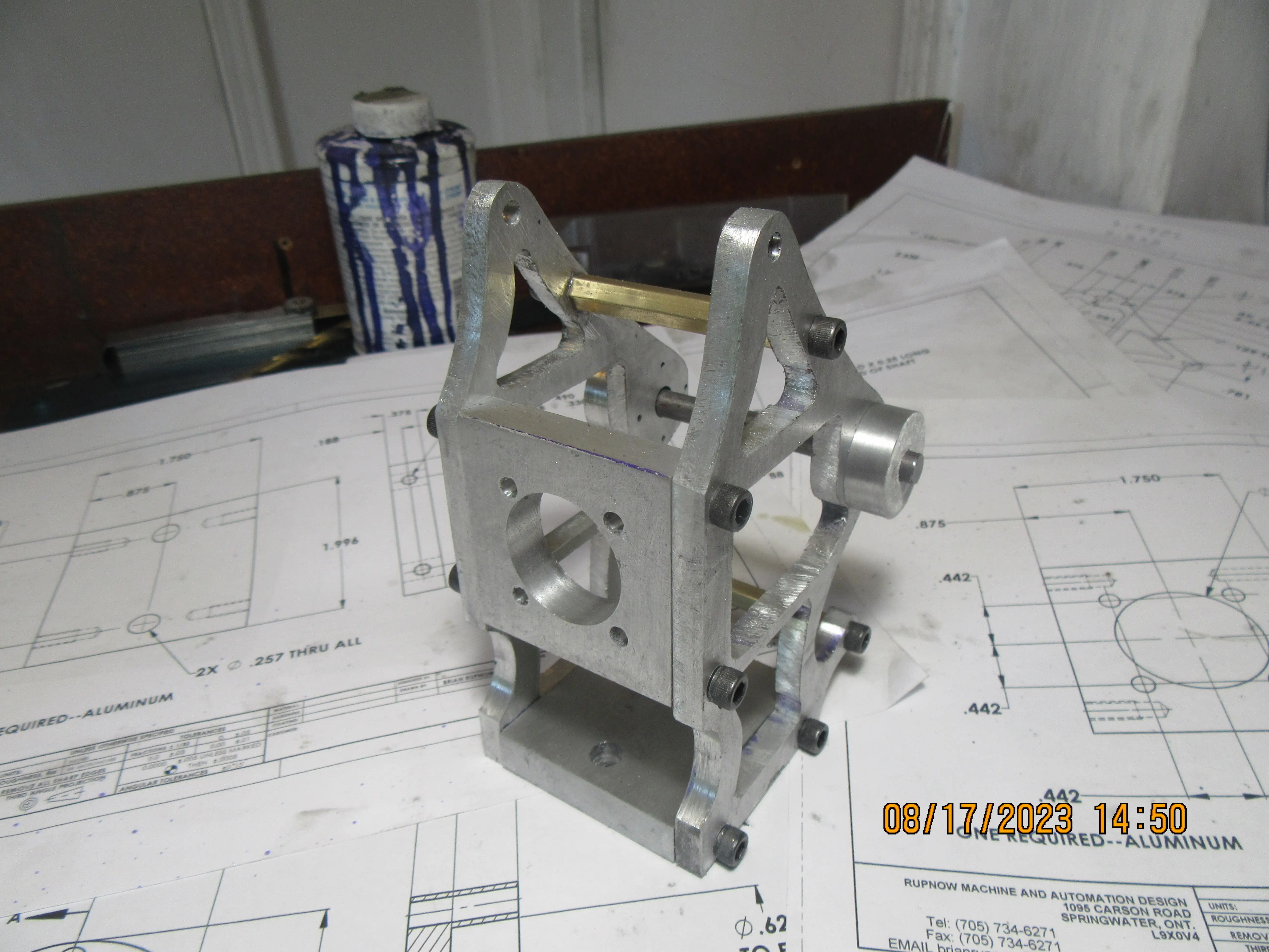


So now it's 6:00 o'clock and I definitely am going to get something to eat!!! Two hours and 49 minutes to carve out a cylinder----but it doesn't have any of the eight tapped holes in it yet.
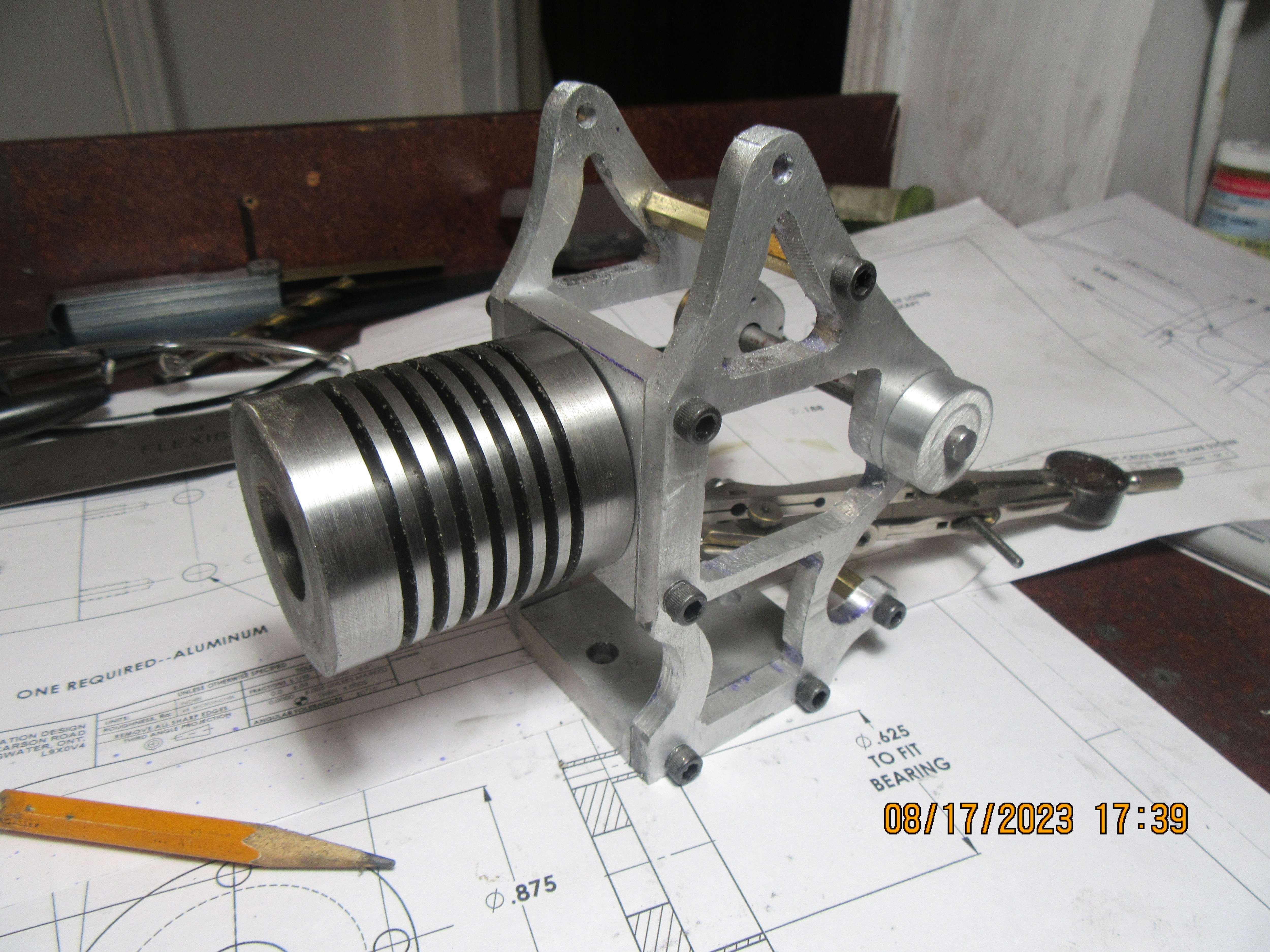

I don't think your skinny rib on the frame looks out of place. But of you don't eat something you'll have a full set of skinny ribs - and we don't want you fading away, yet!
K2
K2
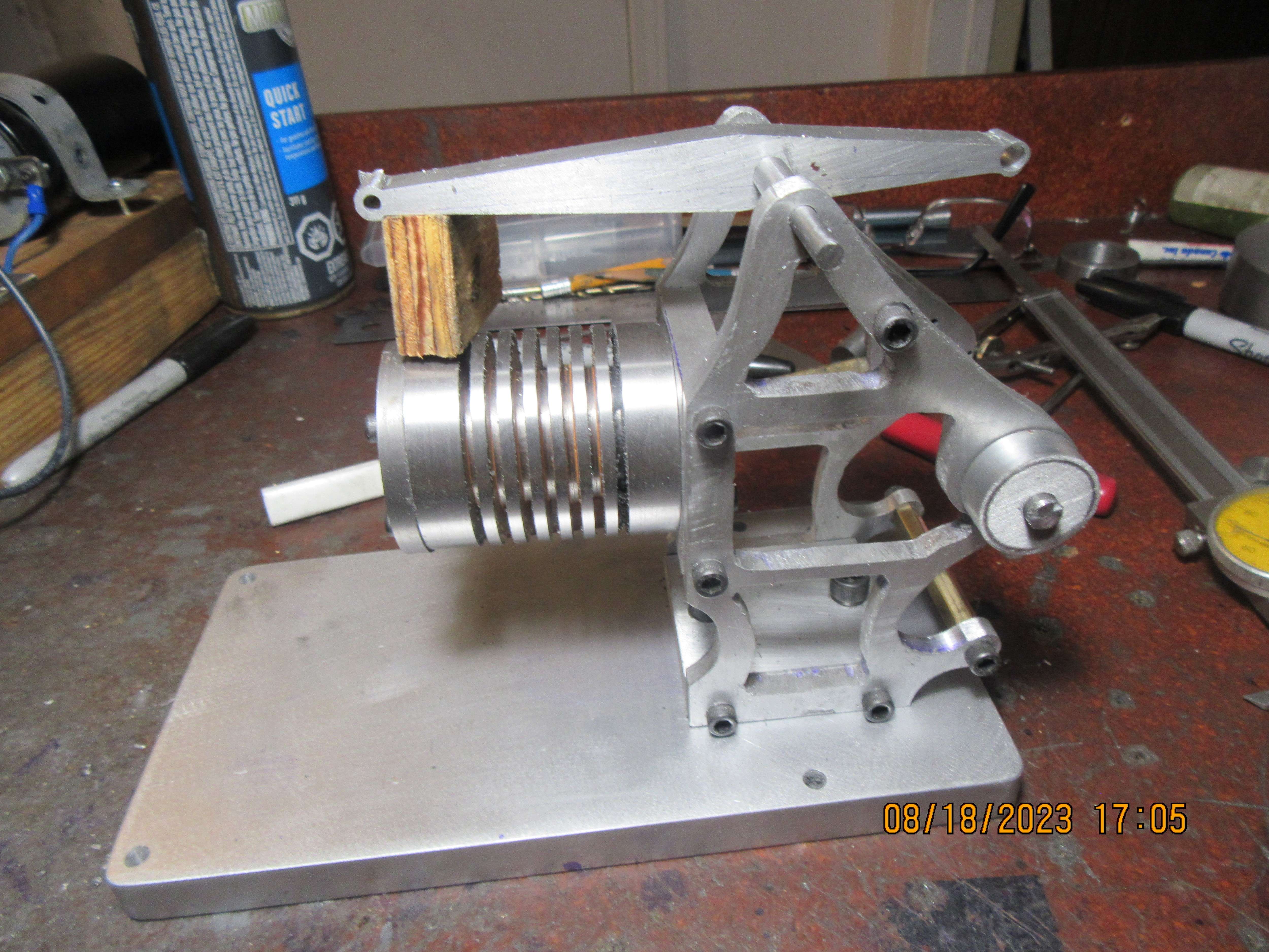
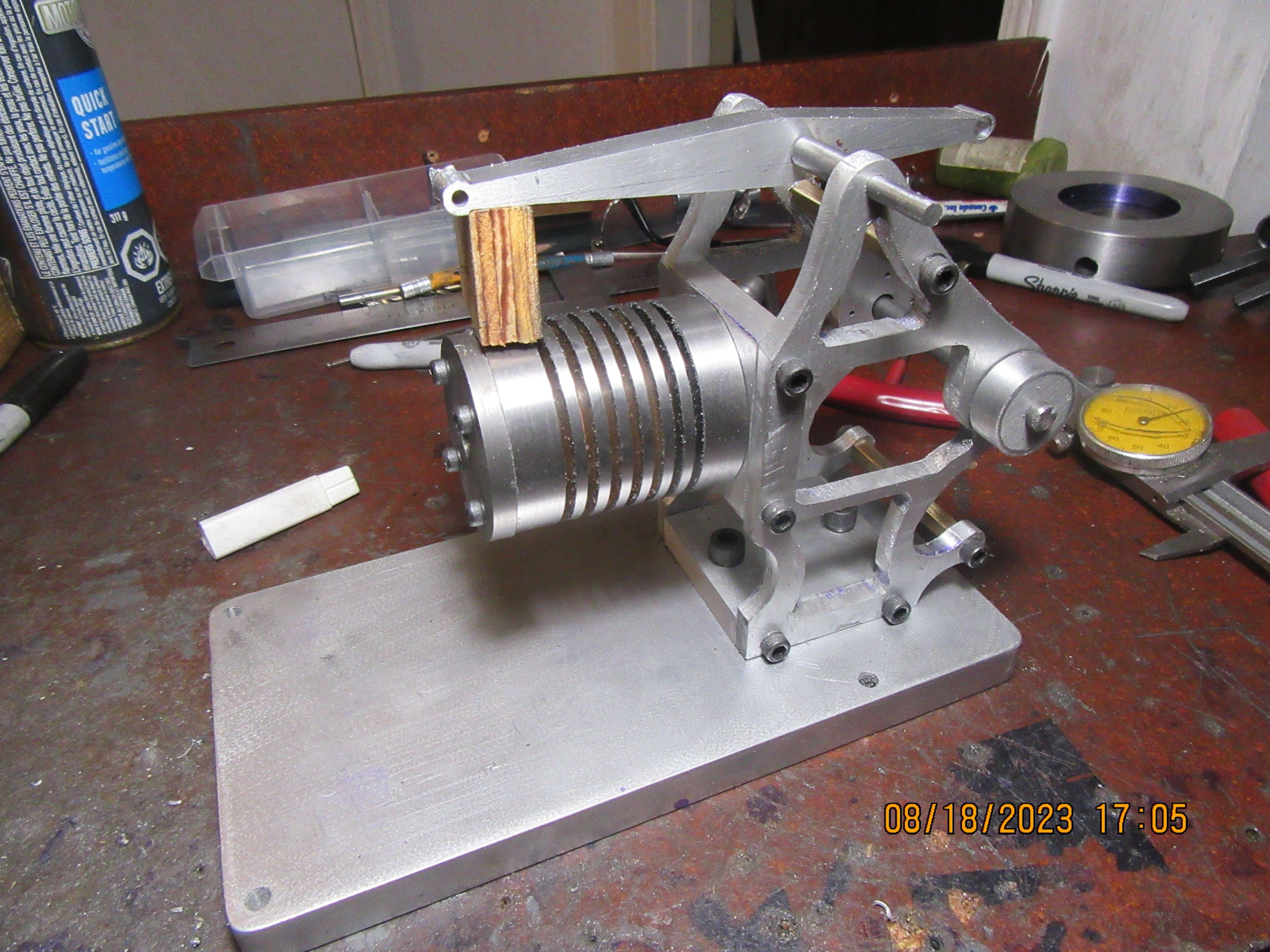
Today I really turned up the heat and ended up with a new sub base, new beam, new cylinder cap and new beam pivot shaft. Time to go eat supper now.


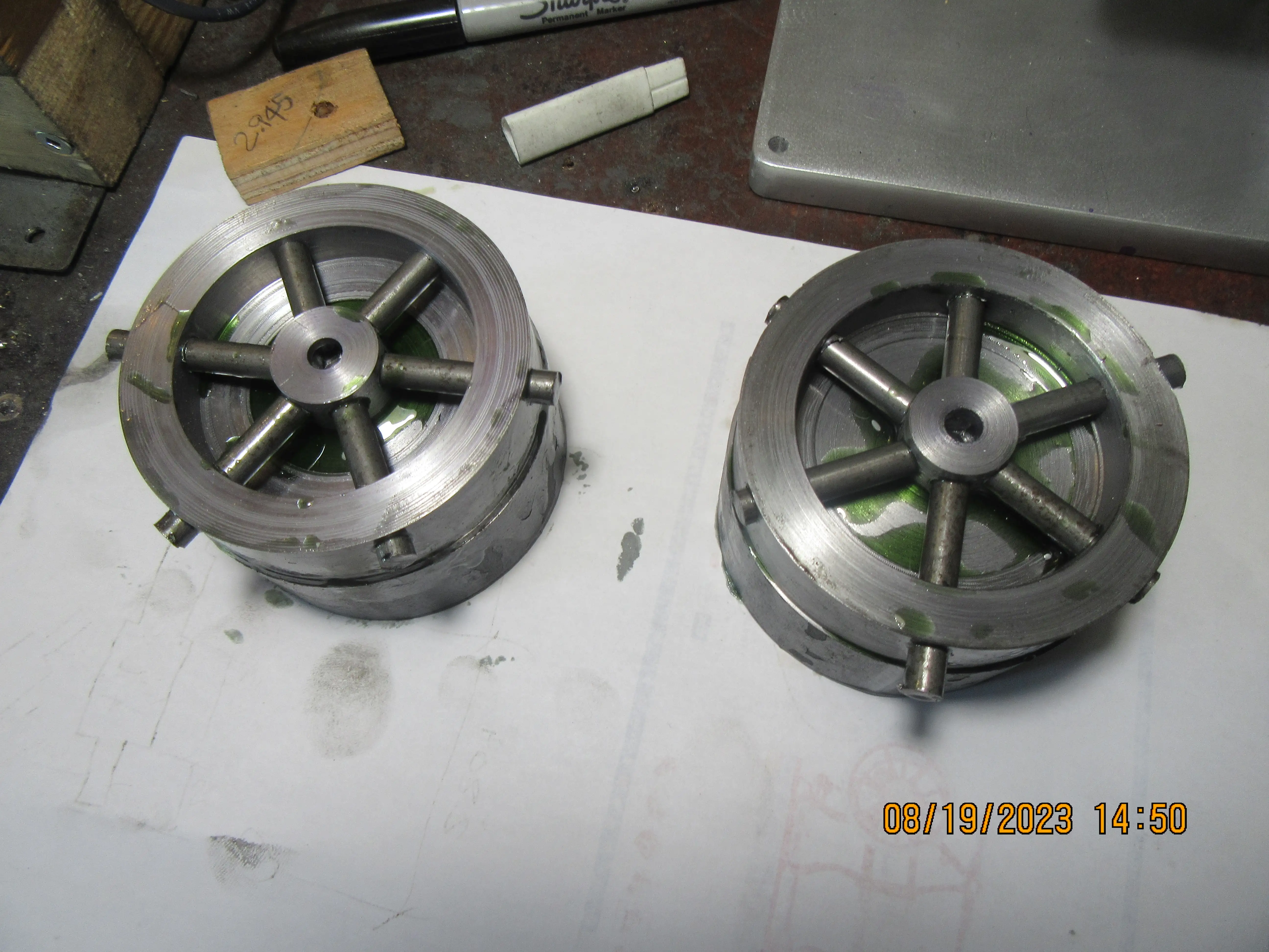
Every time I build a set of flywheels, I seem to come up with a different design. Easiest way is to make a one piece flywheel from a piece of steel, but then there is the question, do I make fancy triangular windows on my rotary table (hard) or do I just drill a series of round holes in the web. (easy but boring). I've made a few flywheels with an outer rim of steel and the web and hub made of aluminum.--Again, this is easy, but an aluminum hub gets chewed up pretty fast if you have to remove the flywheel a few times and then reinstall it during the build. This time I'm going to try something a bit different---I wouldn't recommend this design for a gasoline engine, but for a flame sucker (which at it's very best is a rather wimpy engine) I think this would work fine.
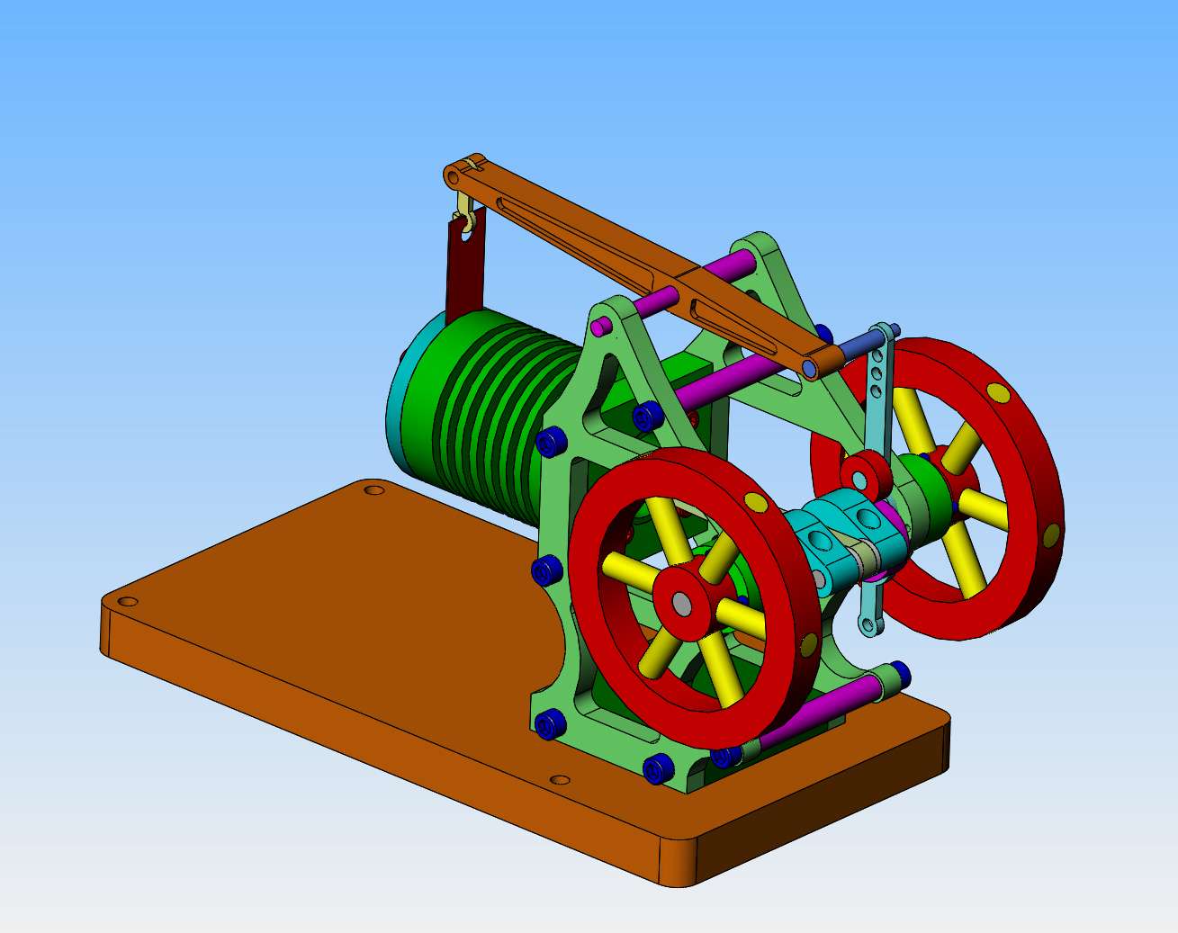

First step will be to turn a 3" diameter piece of round stock as shown. This will keep the outside diameter of the flywheel rim and hub perfectly concentric and aligned to prevent "wobble.
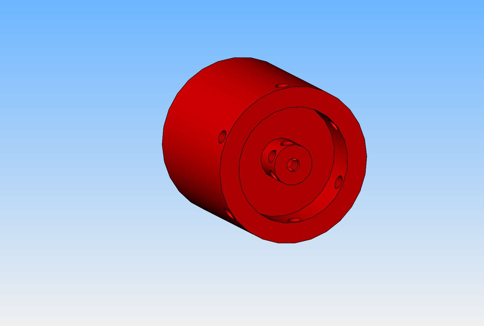

Next step will be to cut all of the spokes a bit longer than they need to be, coat them with Loctite, and assemble them as shown. Be sure and wipe any Loctite off the spokes where they show, as it is difficult to get off after it dries.--An advantage here is that the spokes can be made of brass for extra "bling".
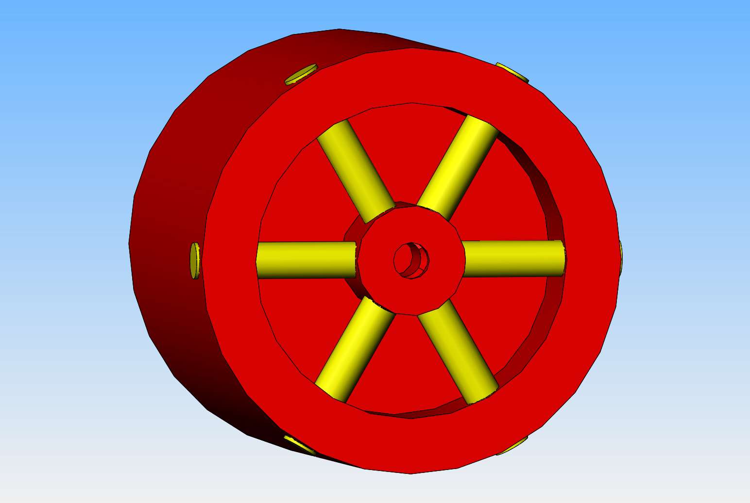

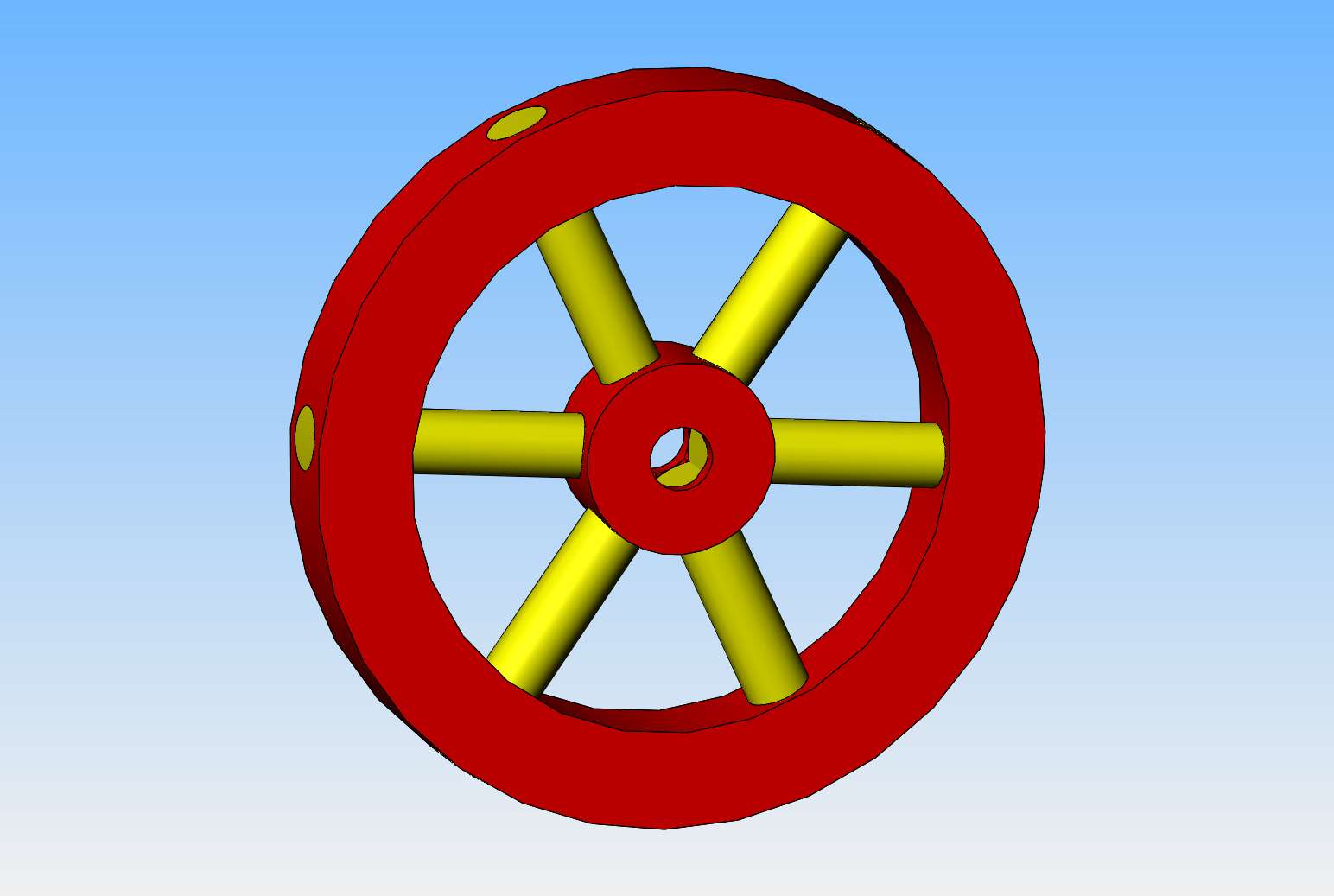
And of course, after the Loctite has dried for 24 hours, turn the outer diameter again to clean up the end of the spokes, run a reamer thru the bore in case any of the spokes have ran thru into the bore, and then part the finished flywheel off.

I like the method!
A couple of ideas?
1:insert a piece of axle -well greased - before adding loctite and spokes. Then the axle won't get stuck with loctite, and spokes won't need reaming?
2: tap the hub for threaded spokes... with clearance (spoke OD) in the rim for securing with loctite.
3: leave the spokes 1/8" shy of the rim OD, then insert some steel caps - held with loctite (?) - then when you skim the rim, the outside looks all steel, so observers wonder "how did you do that?"
Or the steel caps could be made with little suds to screw into holes in the ends of the spokes....
Or....
You stimulate my imagination, but I like your ideas Brian!
K2
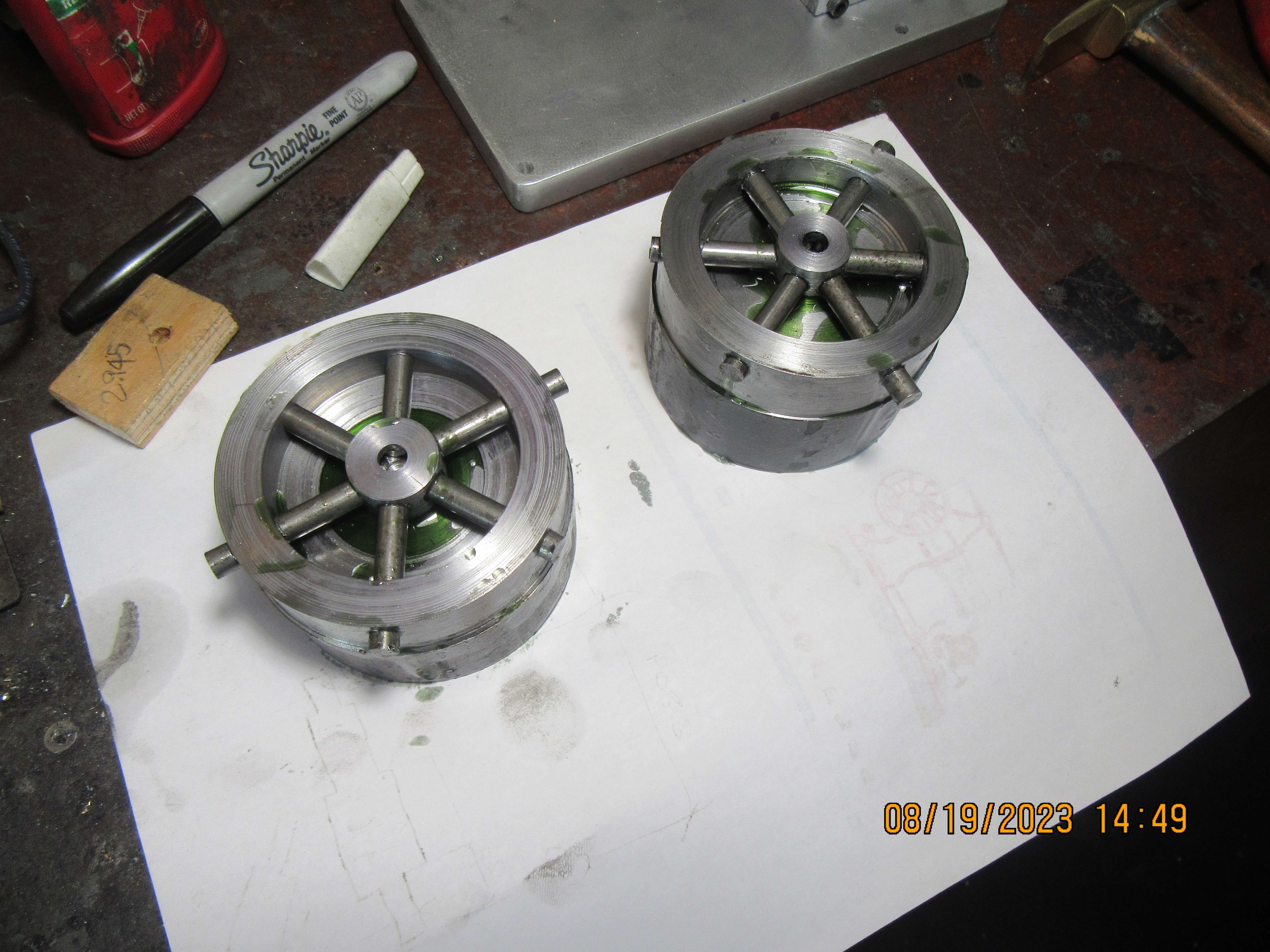
Well, the flywheels seem to have worked out just fine. I'll know more tomorrow when I put them back up in the lathe to do the final turning of the outside diameter and part off the flywheels from the parent stock.


Similar threads
- Replies
- 413
- Views
- 64K
- Replies
- 510
- Views
- 72K


