Merryweather Fire King - a novice build

Home Model Engine Machinist Forum

Help Support Home Model Engine Machinist Forum:

This site may earn a commission from merchant affiliate links, including eBay, Amazon, and others.
Thanks Richard. I have found that at low pressure and giving it a nudge that it goes with a bigger thump at one dead centre than the other. This happens on both cylinders. So as you suggest I think the slide valve is not centred truly. I’ll try and fix this although it is a bit of a pig as I have to do a lot of dismantling to adjust the nut. Unfortunately this will not be for a while as Mrs W wants me to take her away in our caravan. Grrr

Bob
Well you know what? I kikt my wife out of bed and put the lathe there in her place. She lives in the dog house now. Worst part of it is that I have to heat the dog house in the winter for her else she stays up all night howling and bothering the neighbors. She hates her chain too.
 
At last. Can start to get moving on from that blooming engine. So started on the boiler. Some new techniques for me on this part, but very pleased with the result

6B40F062-4E11-40E1-A283-E684E3827213.jpeg
 
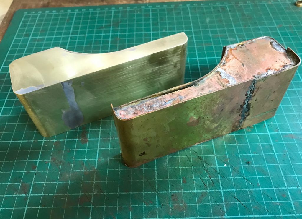
I said that I was a novice ! Made a lovely hardwood former to shape the lower tapered part of the boiler. Sawed off the excess overlap after bending and silver soldered the join after a fashion. Drilled two sets of 36 rivet holes at a 6 degree angle by tilting the head. Being a novice I completely forgot that the burrs from the drilled holes would dig into the wood. No amount of (gentle) tapping or prising would persuade the ring to separate from the former !!!

083093B8-5667-401C-96C6-6F792B05D20C.jpeg


So as a last resort I decided to (hack) machine away as much wood from the former as I could to expose one set of rivet holes

52B0A3BD-A5E0-46A8-837D-C6A85014F8AC.jpeg


The former is actually made from two pieces of 25 mm beach screwed together. So I figured that if I drilled four clearance holes in one piece and bashed four screws it was worth giving it a try to separate the two pieces to improve my chance of getting the ring off the other piece of wood.

7F88FD65-8F91-4BBC-9D05-1D473666A315.jpeg


And bingo, it worked. And finally the ring came off the former in one piece. Got to fettle it up and figure a way of riveting it to its mounting plate. That will be in a while since SWMBO wants to go off in our caravan for a while.

But it gives me an opportunity to think about how to fix those rivets. My inclination is to glue the lower ones in place since they are purely cosmetic and don’t hold anything. Especially as the annealed copper scratches even when you look at it.

When it comes to the upper mounting plate I thought about tapping the end of the rivet and bolting the ring to its mounting plate. The rivets are 3/32 dia which is only a nat’s whisker over 8ba. So a little skim on the end of the rivet would make this possible which would avoid any bashing to form a proper rivet. Any thoughts from you experts would be most appreciated.
Bob
 
Still plodding on slowly thanks to the demands of Mrs W and her other hairbrain projects. But anyway, I have finished the boiler and mounted it in the chassis. Bit of a problem because I used the boiler tube which was 110 mm diameter rather than the 4 in as specified, being the nearest I could find. The upshot was that the rear cross brace and axle fouled. So I had to move them both which was a nuisance. Anyway I got it all to fit and am quite pleased with the results. Here are a few shots of the installation. Next up are the water tanks which will be interesting.

BF8AB14D-9B1F-4CB3-A304-24C5F312271C.jpeg

2E9D0170-B2DE-46F7-B163-AF307DB50F44.jpeg

Sorry about the orientation, BlameSteve Jobs.
Bob
 
Thanks Roger.

So we are progressing with the water tanks. Quite fun metal bashing. Here is one after soldering and the other after a bit of filling with JB weld and then cleaning up:

water tanks.jpg

Next up is the rear platform, and then some painting.

Bob
 
A Nightmare Painting Job

When I finally got to paint the water tank assembly I discovered to my horror that there was absolutely no colour match with the front parts. This was despite the fact that I used the same tin of paint.

Bad paint job.jpg


I contacted the supplier who suggested it was something to do with the primer I had used. He very kindly sent me some isolating primer and some more paint (at a very nice discount). But this was not much better. He then suggested I brushed on more coats. This ended up with an awful finish, so I spent ages with paint stripper to get back to bare metal. In desperation I went to my local paint shop and a very helpful guy found me some spray paint that was almost the same colour as Fire Engine Red. So finally I got a good finish, and assembled all the fittings. I added a few more, such as the spotlights and filler mountings. These were not on the Julius drawings but I copied them from Cherry Hill's model, just to add a bit of detail and also because I like machining little bits of brass!

Good paint job.jpg


Good paint job #2.jpg

Next up the wheels, which look a challenge. Not to mention 60 tapered spokes!

Bob
 
Who said model engineering was interesting and challenging ? Got to make fifty six of theses little blighters to locate the wheel spokes !

Spoke Sleeves.jpg


And then there's the little matter of fifty six spokes.

Bob
 
Who said model engineering was interesting and challenging ? Got to make fifty six of theses little blighters to locate the wheel spokes !

View attachment 134011

And then there's the little matter of fifty six spokes.

Bob
Looks interesting, but I can't tell how big these are, can you put a finger or an inch measure int there? Also, what does the wheel look like, is there two or more?
 
Hi Richard. For your info they are 5mm OD * 4mm Id * 7mm long. There are two rear wheels 132mm OD and two front wheels 101mm OD. If you look at my first post you can see the general layout. When assembling the wheels the centre hub and the outer rim are both clamped onto a plate and machined in position to maintain concentricity. So I had to use the little sleeves so I could actually get the spokes into position. Here are some spokes:

Spokes.jpg


I will show more detail shortly when they are finished.

Bob
 
Yes Aussie, its all made from brass and then glued together. They will then be painted Fire Engine Red. The challenge then will be to add striping round the rim. Never done anything like that before.
Bob
 
Good progress with the wheels. I thought I'd show some of my machining operations as I was using a faceplate for the first time. Any comments from the experts would be post appreciated. My idea was to build the whole assembly on a disc of aluminium which could be moved between the faceplate and the mill rotary table without moving any parts. This way I would (hopefully) maintain concentricity.

The outer rim was made from four strips of brass pinned and glued together:

Rim Frame.jpg


Mounted on the faceplate I machined the outer diameter:

Machining Outer Rim.JPG


Then the inner diameter:


Machining Inner Rim.jpg


Because of the size of the rim I couldn't figure out how to machine the tyre groove on the OD, so I transferred to the rotary table and slowly milled the groove:


Milling Tyre Groove.jpg


I also drilled the holed for the axles with the same setup. Then on the bench I could assemble the axles and the hub:

Fitting Spokes.jpg


I was disappointed to realise that when I machined the tyre groove most of the pins I had put in to hold it all together had been nearly machined away and the whole assembly looked a bit flimsy. So I decided to add a brass tyre at the bottom of the groove and screw that in place. That seemed to work well, but it did reduce the depth of the groove from 8mm to 6 mm. Fortunately I already had the neoprene square section for the tyres and with a bit if experimenting found I could mill 2mm off the thickness - disaster averted. So here is one of the finished wheels. Not sure how to bond the neoprene tyre to the rim though. Any suggestions?

Finished Wheel.jpg


Bob
 
Perhaps silver solder, or even silver bearing lower temp solder, would allow a bit more strength in the joints? In any event, it's a heck of a job you're doing and it's been a pleasure to see your posts!

Stay well and laughing in these weird days,
Stan
 
Thanks Stan. Bit late for soldering, since I've just about finished the four wheels. But I think they will now be strong enough for the limited running it will be subject to.

Will try to keep laughing in these weird days - reminds me of the old Madness song "You've got to laugh or else you'd cry"

Bob
 
Finally got the wheels finished, including some gold striping. Quite pleased with the results. The lines could have been wider, but that was the maximum my pen would open.

Four wheels.jpg


Added minor details to be more like the real thing. The rear wheels have an extra (strengthening?) ring. The chain wheel was solid when I got it, so I machined some spokes for authenticity. Also each hub has a funny fitting in the centre. Not sure what they are; grease boxes perhaps ?

Rear wheel.jpg


And finally it is starting to look like a fire engine:

FK on wheels.jpg
 
A major milestone today!

Cut the gears, which was a new experience for me. Not too many problems once I got the hang of the dividing head. Since I moved the valve eccentrics ages ago I couldn't use the engagement lever as Julius designed it. So I had to resort to what is probably an unorthodox but effect design of my own. The gear slides in a clevis which is moved in and out with a square shaft. A pin is used to lock the clevis in either the engaged or disengaged position. Here are the parts of the assembly (the chain wheels are proprietary items) :

gear parts.jpg

And this is the complete assembly:

gear assembly.jpg

And here installed in the engine:

gears installed.jpg

And finally I have drive to the wheels. Fitting the chains was a nightmare. To start with I made the chains such that they just fitted with a minimum of play. But the links kept jamming. So I tried making them a bit longer. But you can't get a bit longer because you have to increase by one whole link. The end result means that the chain flaps around terribly. So I'm going to try inserting some sort of tensioner. Anyway the engine does drive the wheels which to me is a major achievement. I was quite pleased that the control valve does indeed control the speed. Pity the wheels are a bit wobbly, so I'll have to have a look at that!


Latest posts

Back
Top