Horizontal Mill Engine From Kit

Home Model Engine Machinist Forum

Help Support Home Model Engine Machinist Forum:

This site may earn a commission from merchant affiliate links, including eBay, Amazon, and others.
Here's a pic with vise stop behind...can't install it...

IMG_4484.jpg


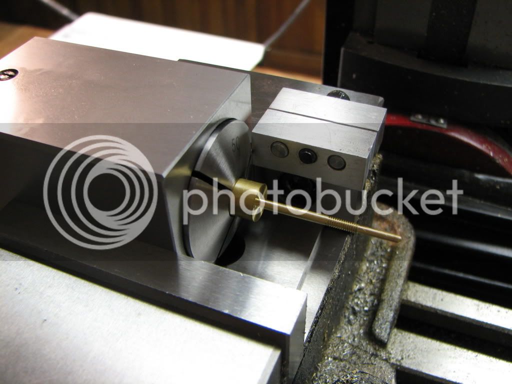
Here's a pic with vise stop in front...

IMG_4485.jpg


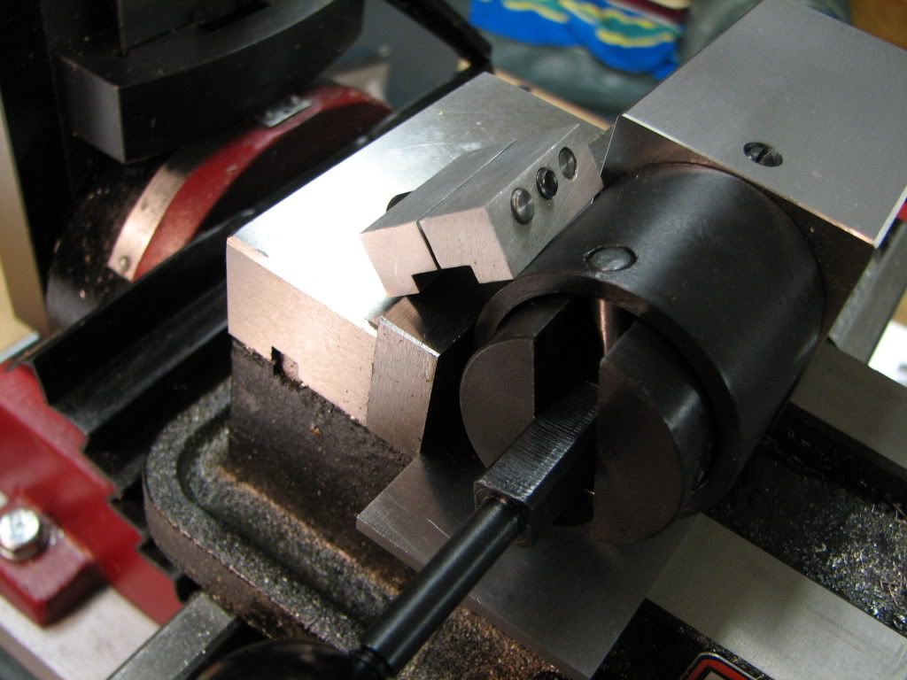
Here's a pic using a 1-2-3 block in back up against the collet...

IMG_4486.jpg


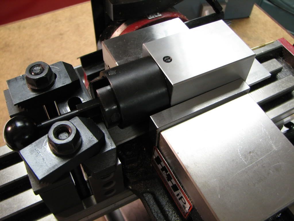
I don't know if this is what you all meant...

[EDIT: I don't think that last shot with the clamps is right. Now it's not just the collet block that has to be square...but the draw bar thingie too. Needs to be in front. Okay. Enough of this...gotta mill. Back to Spindex ;D]
 
Hey Zee,

If it got you the part you need you did it the right way... ;D

Dave
 
Nice Dave! Thanks.

Well here it is...
Sorry...I have no tan M&Ms either. I'm lucky to have this one...

IMG_4490.jpg


The material, as provided in the kit, is too short to follow the unmentionable instructions. After milling the square, I was supposed to put it in the lathe and part it off. No way. Nothing to hold onto. I ended up chucking it such that I was holding onto the thin diameter. Which worried me that it would bend with the pressure. I took it easy...light facing cuts...and it went very well.

Then I set it in the vise, used the edge finder to find the center of the square, and center drilled, drilled, and reamed it.

I'm still doing poorly at measuring. For example, in the lathe I measure at least 3 times and got the distance to 0.19. But after taking it out of the lathe and measuring again, I came up with 0.185.

In fact, when in the Spindex, I was supposed to get .19 on two opposing faces and .188 on the other two. Just a .001 off from the other two, right?. Once I was done I found all four to be at .186.

The other difficulty was sanding...a jig would have helped here. You can't hold onto it and not have it slip. The result is faceting (if that's the right term).

This has gone well...well enough that I'm seriously thinking of do-over for the piston rod. But I'll probably wait until all the parts are done and I see how things fit/look/work together.

 
Good going Zee - you've made a couple of great looking parts since I've last posted :bow:.
(Been sitting in the peanut gallery - away from the edge of the roof ;) )

Regards, Arnold

PS - You're cheating on the M&Ms; if you can't get the size right, at least use photoshop or something to make it tan ;D
 
Zee, Zee, Zee, If you don't have room to get the vise stop in there, put some packing between the vise jaw and the collet block until you do!
 
First thing to do is put that collet clamping thing away and get out the locking ring. I've used a collet block set for twenty years or so and never had occasion to use that clamp. The ring is far more useful and, major point, allows one to stand the collet upright in the vise - a feature you will find penultimately useful.

When I got my block set, I didn't have a spanner to fit the locking ring either. What I did have is a POS "wrench" acquired in a box of junk at a yard sale. It was just a piece of die cut steel - didn't even remotely resemble a proper forged wrench. I keep junk like this for just this sort of application.

I cut off one jaw of the wrench. (The fact that I could do that with a hacksaw gives you an idea of the quality of the wrench.) Then I used the bench grinder to grind into the other jaw in such a way as to leave a single "tooth" at the tip of the jaw, said tooth filed to fit the hole(s) in the locking ring.

It's perhaps one of the ugliest bits of bodgery I've ever done but it worked so well that I still use it - though I try not to look at it when I pick it up.

Ok, you don't have a wrench from a yard sale. Take a piece of 1/8" or so flat steel - the hot rolled crap from Home Depot is fine - and hack the appropriate shape and tooth into it with whatever you have available. (Angle grinders are great for this sort of caveman machine work.) Wrap some duct tape around the handle to protect your hands and Bob's your father's brother.

The spanner doesn't need to be pretty or very strong, for that matter. What's important is that that clamping thing is always going to get in your way and you need to use the ring.

I made the valve rod much as you've done because I built the engine so long ago, before I had the tools I have today. A much cleaner way to make the part is to start with 3/16" square stock and, holding it in a square collet, turn the shaft. Then you don't need to faff about carving the square end on it.

Aside: Nobody ever has enough collets but, after getting an adequate set of round collets, I find the square collets to be the most useful addition to the collection. There have been a few occasions when hex collets would have been handy but the square ones get lots of use in my shop.

Don't sweat the dimensions of the square section. It's just there to provide some place to attach the valve connecting rod.
 
Thanks Arnold.

Gosh darn it Tel. Lack of experience and practice I guess. I've done it a few times now when making a part. The wetware must be drying up...it didn't occur to me to do the same to a tool.

Marv...thanks. Yeah...when I got the collet blocks I was a little surprised. I would've wanted the spanner instead of the clamping thingie. I suspect once I acquire one (made or purchased) I won't be using the clamping thingie.

I don't know what a POS wrench is...I'll have to look it up later.

Square collets are definitely on my 'to get' list...along with the spanner ;D. It did occur to me that square stock would have worked...especially as I have two more pieces that require similar shaping.


That's one of the beauties of making stuff yourself - with my home made MT2 collet blocks all I have to do is slip a big washer under the head of the drawbolt, so it butts uo against the end of the vise jaws

block1.jpg
 
tel said:
That's one of the beauties of making stuff yourself - with my home made MT2 collet blocks all I have to do is slip a big washer under the head of the drawbolt, so it butts uo against the end of the vise jaws

block1.jpg

Gosh darn it Tel. ;D

I'm getting close to getting my 4th 'little engine that sorta is' done. Now that I feel I'm in this for good...and actually have some success...I'm starting to develop an interest in making tools and other things. I am really looking forward to some time off this Christmas.
 
steamer said:
If it got you the part you need you did it the right way... ;D

So much truth in that Dave. Especially as a beginner hobbyist. Thanks.

Thanks kvom. Just waiting for the 'to get' list to get a little longer. Won't be long... ;D
 
I have the eccentric rod and connecting rod to do. They are similar in shape. Boxes on the end of a thin rod. The connecting rod is tapered.

The rods are maybe 1.5" to 1.75" long and .09" at the narrowest.

The 'not to be mentioned' instructions tell me to turn the connecting rod down to the largest diameter of the rod and then the smallest diameter for a little distance. Then file the taper.

As what seems usual for this manual, the part is hanging out in the breeze.

I'm using round stock. Brass.

So how to do this?

I've started with the eccentric rod. But I took some longer stock, drilled one end, and mounted it in the lathe with a live center.

I'm not sure how to turn this though. Switch between left and right cutters? But I'm thinking the part will bow in the middle (move away) as the diameter gets smaller.

Use the parting tool at the ends, turn down a little, then file?

Your suggestions are greatly appreciated.

 
It just occurred to me. This engine looks a lot like Elmer's #43.
 
I 3rd/4th/whateverth the ditch-the-knob-thingy crowd on the collet blocks. You don't even need a pin spanner if you don't want one (though having one saves buggering up the ring with a pipe wrench if tightened externally)-- put the part in the collet in the block and hand-tighten the ring. Place block in vise. With handy round rod of approximate pin-hole diameter, poke into nearest hole and move in a tightening direction tommy-bar style.


Twmaster said:
It just occurred to me. This engine looks a lot like Elmer's #43.

Yep. That's the one.

So anyone who's built one...like Marv ;D...is welcome to help me figure out the connecting and eccentric rods.

Thanks shred. I had to look up what a tommy-bar is. Looks like a short rod would work.
 
I just realized what a long post this is... And the wealth of advice it contains... I'll read it all from the beginning -- seems like a wonderful journey.

tom
 
Thanks tom.

Once you get past my swarf...there's a lot of good parts in there from some very helpful and knowledgeable people. :big:
 
zeeprogrammer said:
Yep. That's the one.

So anyone who's built one...like Marv ;D...is welcome to help me figure out the connecting and eccentric rods.

Thanks shred. I had to look up what a tommy-bar is. Looks like a short rod would work.

Zee This is how I would make the eccentric rod.

Option A; Cheat by making it out of three pieces. Tricky but doable.

Optiob B; Cut and then finish by Milling a 1/8" x 3/16" strip 1/2" or more longer than the total overall length of the finished eccentric rod. You may need quite a bit more excess on the head stock end for a miniature dog leg which you'll probably need to fabricate. You can hack of most of the excess later to minimize the trimming in your mill. Lay out the center lines for the drilled and tapped holes, make sure you are centered on the work piece, because later 1/4" will be trimmed off each end. With the drilling and tapping done center drill both ends on center for a head stock and tail stock center. Simply turn down between the previous lay out lines down to the specified diameter. Return the work piece to the mill and trim off the excess 1/4" from both ends by hanging the excess out the side plus about .030" or whatever is prudent so that you don't trim off the sides of you vice.

Piece of cake!!!

Go for it and have a blast!

=MB
 
Back
Top