Horizontal Mill Engine From Kit

Home Model Engine Machinist Forum

Help Support Home Model Engine Machinist Forum:

This site may earn a commission from merchant affiliate links, including eBay, Amazon, and others.
After nearly 50 years on the left coast, I've gotten to the point that virtually no one can detect my origins from my speech or writing.

That may be but with a name like Klotz you are labeled for life. I do a lot of work in that area. In fact. I'll be in Lancaster tomorrow....

 
mklotz said:
Hunh? Methinks you've been around the Pennsylvania Dutch too much. Next thing you know you'll be using expressions like, "Come ahead back."

Could be. Or not enough. Or it's southern Missouri, or northern Arkansas, I doubt it's mid-Illinois. I sometimes stop and catch myself at work before saying something no one understands. Not that that doesn't happen anyway. ;D

Well...I've thought about that valve stem all day. I'm already letting a poorly made piston rod get by me (for now). Having two shoddy parts is two too many. I haven't got much invested in the valve stem...so I decided to re-do it.

Now...remember the crank handle? The evil crank handle? Well I'm looking at the 1.4" of .085 to .095 material sticking out of the chuck and I think...maybe I can just bend it and snap it off.

Oh how this stuff likes to mess with my mind. That's right...bent right over nearly 90 degrees.

Phooey. ;D
 
We go from 'phooey' to woohoo1 woohoo1

I was talking about the valve stem with Vernon on YIM and he made a little drawing...well that sent me off...

At first I thought this...

IMG_4473.jpg


But then went to this (after shortening the handle and cleaning up the end)...

IMG_4474.jpg


Then I used the parting tool to turn the larger diameter down and then the smaller diameter for the 5-40 thread. Here it is about to be parted...

IMG_4475.jpg


Then I flipped it in the chuck with a 'light' hold and threaded it...

IMG_4476.jpg


Sorry the pics aren't as good as I'd hoped.

Couple a boo-boos that I thought about while doing the job but forgot when it came time to...

For one I wanted to put a radius at the end of the threaded portion before finishing the part. As it turned out...it wasn't needed.

I also wanted to use a thin blade and put a thread relief at the back end of the thread. But that won't hurt either as the reversing lever will be there.

And here it is sitting in the engine...

IMG_4478.jpg


This was really cool! Thank you Vernon. You still owe me beer...but thank you.

I wasn't happy about the valve stem...didn't think I'd be doing anything tonight...and instead I end up with a finished part...and the 'evil crank handle' at that!!!

woohoo1 woohoo1
 
Wow, that looks a lot better in'real life' than it did in Yahoo's "Doodle"! Congrats! :bow: I still wonder why it bent this time, and not the last...what was it...four tries? From the same piece of brass? Strange stuff.


When did you get tailstock die holders?


zeeprogrammer said:
This was really cool! Thank you Vernon. You still owe me beer...but thank you.

Not "beer"!... just A Beer! ONE!! Here, let me point it out for ya. :D
BTI.jpg
 
A nice save, indeed, but I want to know how, after all the hints we gave you, you managed to bend the valve rod. From the picture it looks as if you tried to turn the full length down to 0.093 despite knowing that that wasn't going to work. Was this another case of having to personally verify that the instructions were indeed wrong?
 
mklotz said:
A nice save, indeed, but I want to know how, after all the hints we gave you, you managed to bend the valve rod.

I don't know what you're onto here Marv. There were a few more inches of brass in the head stock. I thought I'd just snap the valve rod off and try again. The bend was a complete surprise. What hints are you talking about? If you're talking about still saving the part as a valve rod...it would've been too late anyway. The diameter near the parent stock was too small.

mklotz said:
From the picture it looks as if you tried to turn the full length down to 0.093 despite knowing that that wasn't going to work.

Knowing? Yeah Marv...that would be pretty stupid. No I didn't 'know'...I had my suspicion. And I'd rather confirm a suspicion and learn than to continue wondering. And as I've said before...I don't just question manuals.

mklotz said:
Was this another case of having to personally verify that the instructions were indeed wrong?

The short answer is 'no'. The long answer would require me to address the implication....but the long answer is still 'no'. ;D
 
Zee,

Obviously, I've upset you with my question. I sincerely apologize. I won't offer any explanation other than that I'm having some problems at home and it crept into my writing - not really a valid excuse.

I'll try to be more politic in the future. Again, my apologies.
 
I admit to having been upset...I can't say myself why I was overly sensitive.

No apologies needed Marv..but thanks.

I hope things clear up very soon for you.
 
Okay...knowing there are no 'silly' questions on this forum...I'm going to try anyway... ;D (As an unapproved member of the Peanut Gallery...I get to ask for free.)

Taking another run at the valve stem...

I've turned the first .41 down to .071. I did not go farther yet. And yes...no noticeable deflection. Looks good so far. (Thanks to Dean and Marv for some great tips.)

The next 0.31 is supposed to be turned down to .095. Later this will be threaded for 3-48. (Wait for it oh knowledgeable ones...)

After that, the next 0.64 is turned down to .0938.

The part fits into the steam chest that has a .0938 hole. So the final 0.64 makes sense to me. I'm trying to figure out how the 0.95 gets past the .0938 hole.

Does threading it reduce it to, or less than, .0938? Must. Otherwise, it can't get past the .0938 hole in the steam chest.

The 'never to be mentioned again manual' says to use the threaded section as a pilot for the steam chest. Really? .095 into .0938? (Here you go oh knowlegeable ones...I won't even go into the fact that I have two sources that say the diameter for the 3-48 should be 0.099!!!)

Okay..maybe no question....to get past the .0938 hole in the steam chest...the diameter must be .0938...or smaller ;D. So I'm going to turn to .0938 and then thread the 3-48 on that for the required distance.

Stop me now when you see the error of my ways.

You have some time cause I have to figure out how I'll know I've threaded for the required distance.

I'm thinking to turn to .095 (as the 'never to be mentioned again' manual says), thread it to 3-48 and then turn the rest to .0938...possibly skimming off the tips of the threads.

Aren't you glad you're reading this? :big:

Maybe it's the upcoming holidays.


Vernon said:
I still wonder why it bent this time, and not the last...what was it...four tries?

When did you get tailstock die holders?

Not "beer"!... just A Beer! ONE!!

Forgot I hadn't replied to this 'post'.

Four times! Thanks for reminding me Vernon. Thanks. ;D

Die holder was gotten months ago. Nice tool. With that and Arnold's thread on making die holders...I hope to make some over the holidays.

The nice thing about the internet, this forum, and people's memories...you can't get away with it...it was 'beer'...NOT 'a beer'. And certainly not the 'dry' one you sent me. :big: (Thanks again guy.)

By the way...I've been recording our YIM chats. ;D
 
In reply to your concern about the valve rod diameters. The hole going through the steam chest spigot is shown as .094" . The diameter of the threaded section and the non-threaded section should be turned down to .093".

Thread the 5/16 section and don't concern your self to much with charts showing theoretical screw diameters. My chart says 3-48 being .0973.

Before removing the valve rod from your lathe test fit the steam chest. If the threaded are won't slide in easy, simply but carefully dress it down with a fine file.

I run into this situation with threading .125 rod 5-40, The rod will not pass through a .125 hole when it needs to like on a piston rod to piston. Yes the threading can and does increase the outer diameter. A "file slap" as I call it solves the problem. Fact is you really don't need 100% thread on a rod or in a tapped hole. Most guys will go with 50% to 70% thread and call it a day. Play with the adjustment on your split die and practice on identical diameter material to achieve a snug fit between the valve rod thread and the adjusting nut.

EDIT. If that is not acceptable than look into opening up the spigot hole to 7/64" (.1093) and machine the non-threaded area of the valve rod .109".
-MB
 
Too late!!! It's done!!! And I'm happy (so far)... [EDIT: Not in reference to MB's post...I saw that after I was typing. My reply to his is included.]

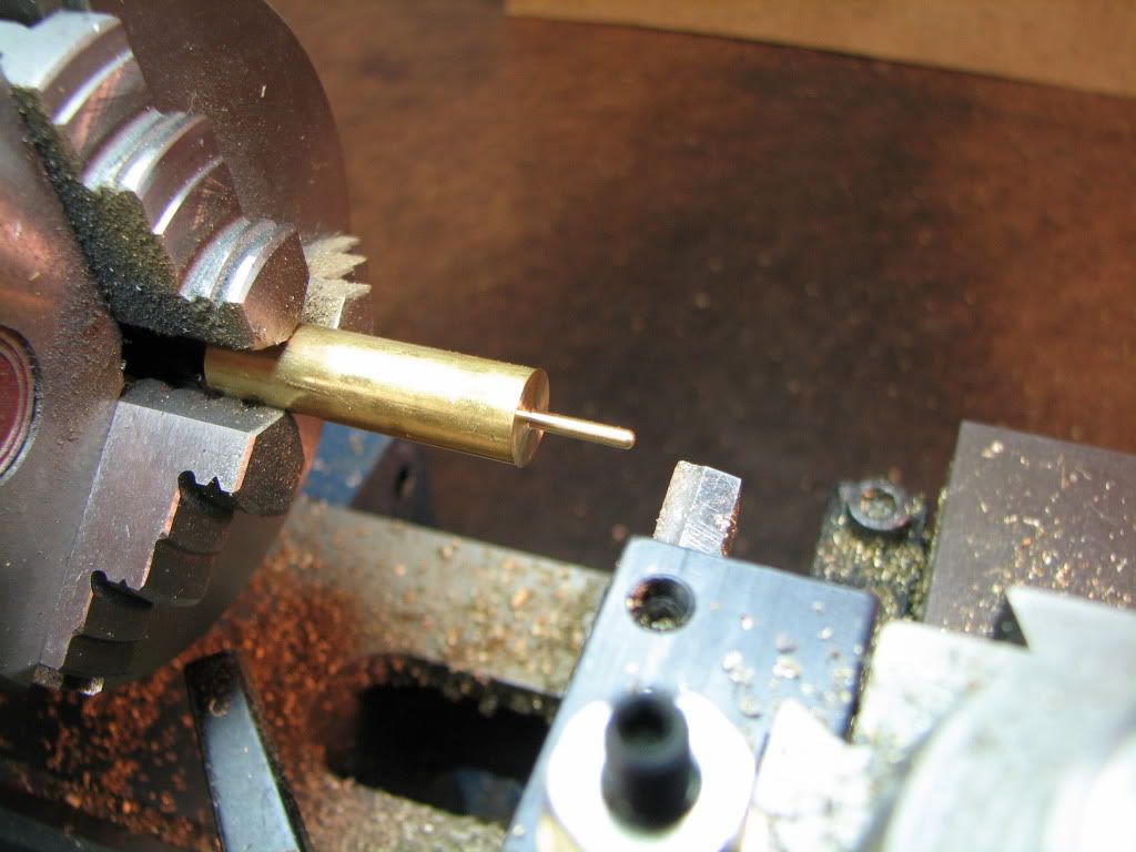
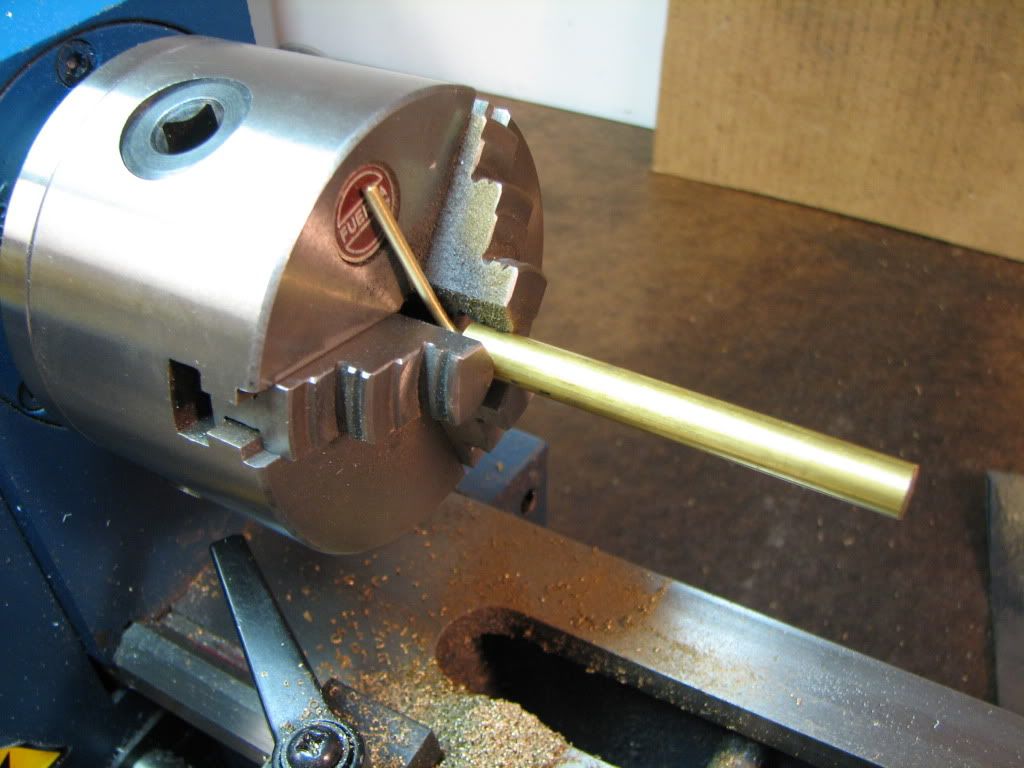
Here's a pic of the first .071" with radius.

IMG_4479.jpg


Here's a pic of the next .31 turned down to .095.
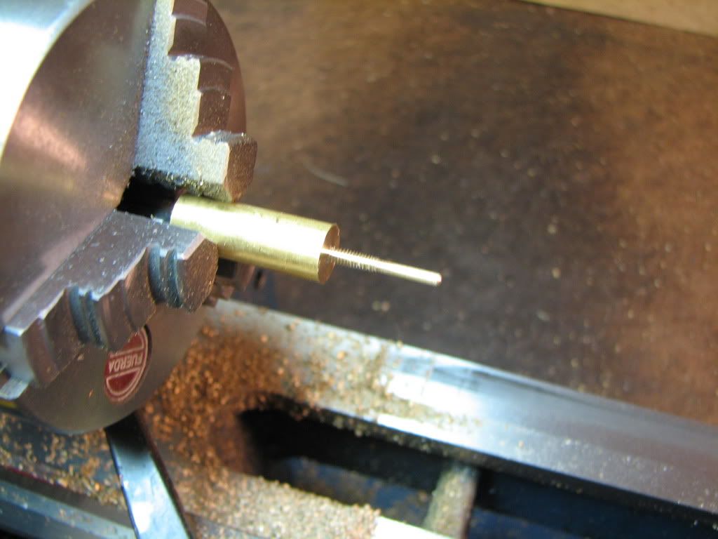
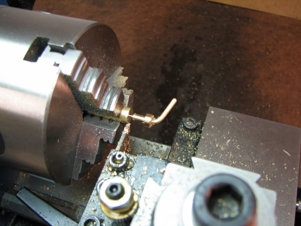
IMG_4481.jpg


And threaded.

IMG_4482.jpg


I turned the die around to chase the thread...it marred the first .071 a tad but it cleaned up fine.

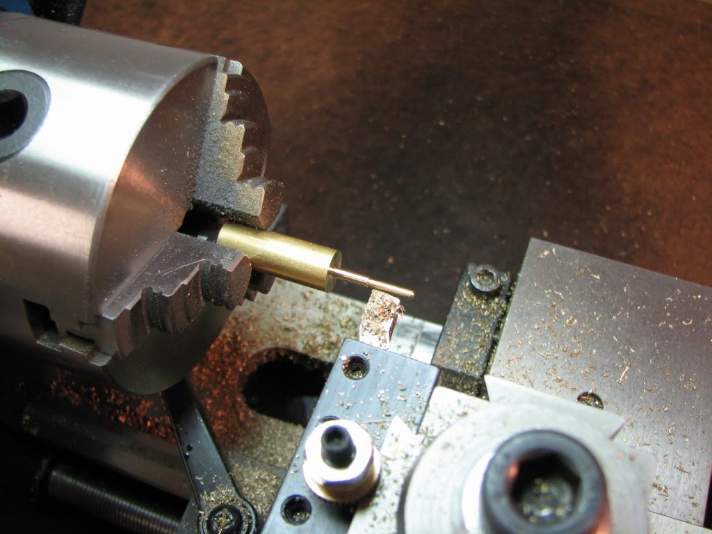
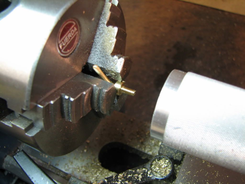
Here it is with the next .065 turned down to .0938. First attempt was a little tight getting past the thread and then to the shoulder. I took some scotchbrite to it...and it slipped on pretty nicely.

IMG_4483.jpg


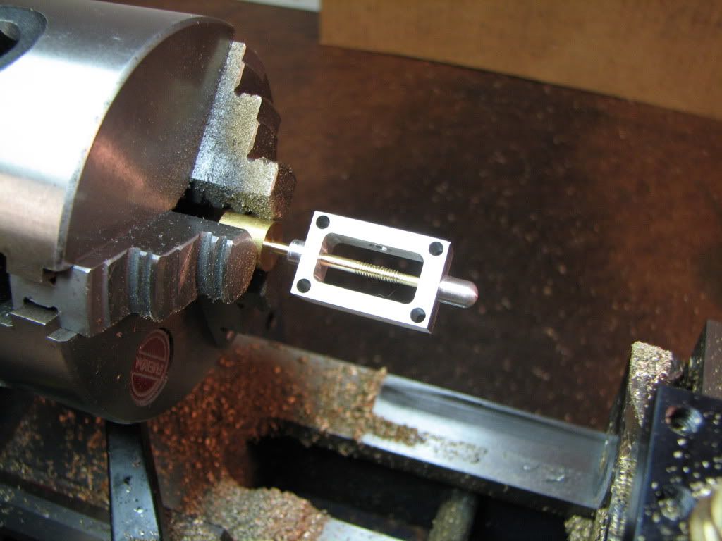
I also put the little nut on the valve stem and was pleased to see that it fit nicely.

MB...thanks! I saw your post while typing this. You mentioned the diameter getting larger with threading. And yes, I noticed that after threading, the OD went from .095 to .097 if not .099. I'm not surprised that your drawings show a (slightly different dimension from mine. In fact, when I saw the .0938 I thought it was kind of funny, bordering on ludicrous, for a beginner's kit. It's hard enough to get within .001 of anything.

For those of you with hard hearts...turn away now...off topic and 'slobby'...

I've got a few tears in my eyes. Wife is watching 'Dancing With The Stars' and they were doing a 'Vienna Waltz'. So I went upstairs to take a look. When we were married (1975), our song was John Denver's "Annie's Song". It's a Vienna Waltz. She and I have done some ballroom dancing, off and on, since 1982. 3 years ago my oldest daughter got married and we took the opportunity to try the Vienna Waltz with "Annie's Song". We were too old to do it justice...but the look on my daughter's face was priceless.

Yeah...a new year must be approaching. I'll try to keep the maudlin moments to a minimum. ;D
 
Now that I've dried my eyes...woo woo!

I get to use my 5C collet block!

[EDIT: The 'never to be mentioned again' manual is using a Spin Index. No need. I just need to square off the end and drill a hole through it.]
 
Zee, the way you cut the small threaded shaft from the larger stock is just right! Let the stock piece of metal be its' own work holding device, just like you did it. You've got the world by the tail, my good man.

Your remembrance of your waltz and daughters wedding hit my soft spot. I have fond memories of the day my own daughter was wed. She was so happy. Still is.

Dean
 
Damn but I keep 'forgetting' how small this thing is..... occasional reality checks helps..... looks good mate...

R
 
Thanks Dean and Artie. Very much appreciated.

I started looking at the part sitting in the collet block and trying to figure out my approach. Well I think I need to change.

While the collet block would work...I would need to reset the X axis on the mill every time I rotated the block. That can (will) lead to error. So it's the spindex for me.

The second thing I'm thinking about is how to get to the needed Z. I could touch off the stem and move the head up....or touch off the larger diameter and move down. (Either method requiring a measure of the part being touched off.) I'm thinking I'll touch off the larger diameter and move down. Backlash will have been taken care of because I'm still moving in the same direction. And while I believe this is not the most accurate since the larger diameter has not been turned...I figure the error will be within the tolerance for a dimension called out as 0.19.

No? Yes? Too late...as I press Post I am turning around to my mill ;D

This just seems pretty fundamental. I'm starting to question every move I make.
 
While the collet block would work...I would need to reset the X axis on the mill every time I rotated the block. That can (will) lead to error. So it's the spindex for me.

I thought you had a vise stop. Use it to ensure the collet block returns to the same position.


The second thing I'm thinking about is how to get to the needed Z. I could touch off the stem and move the head up....or touch off the larger diameter and move down.

I've never had much luck touching off as you describe and maintaining accuracy.

Take a light cut, rotate collet block 180 degrees and take another cut at the same setting. Mike across the flat you've just created* and calculate how much more z-axis cut you need to put on to get to 0.19.


--
* This is one of those situations where a 0.5" micrometer is awfully handy for getting into those little slots. I have two of them and use them frequently.

http://www1.mscdirect.com/CGI/NNSRIT?PMPXNO=9036959&PMT4NO=74682904

Highly recommended as stocking stuffers.
 
Even without a vise stop, you can use a parallel or 1-2-3 block to set the collet block position repeatably* off the side of the vise or whatever's handy.


* Assuming your collet block is reasonably square. It's worth checking beforehand.
 
Not too late as it turns out. I was interrupted by the call to din-din.

Thanks Marv. I do have a vise stop. I'm always forgetting it. This will move the collet block such that it sits on only one side of the vise. I suppose I can sit it on top of a parallel that will span the vise.

Funny about the micrometer. I happen to have one I bought for an electronics lab course some 30 years ago. It was a required purchase so we could measure the diameter of resistor leads so we would know what to specify for holes in printed circuit boards. (The instructor did not appreciate my pointing out that it could be looked up or that standard holes seemed to be appropriate.) I was just talking about it with a friend and used it for the first time since then the other night.

I haven't used the collet block yet so I'm thinking I'll give it a go.

[EDIT: Snookered with respect to the vise stop. No room for it. The draw bar thingie (name please?) is in the way. Maybe could use the nut but I don't have the spanner for it yet. Could put the vise stop on the other end but that doesn't seem right. Vise stop would be in contact with the collect itself...not the block...and only a corner at that. Shred's suggestion is still possible but I'm not sure how to do it. I'll try and post some pics.]

Thanks Shred. I suspect the collet block I have is 'square enough' for this job...but how do you verify it? Some stock in a collet, a DTI in the spindle, and rotate the block 90 degrees and see if the DTI changes?

Thanks Phil. Yep. My head will eventually get through those walls. ;D
 
Back
Top