Horizontal Mill Engine From Kit

Home Model Engine Machinist Forum

Help Support Home Model Engine Machinist Forum:

This site may earn a commission from merchant affiliate links, including eBay, Amazon, and others.
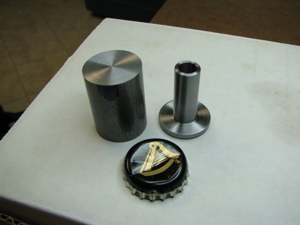
I managed a little bit of work tonight and saw that I had taken a picture earlier of the 'crosshead' in making...

IMG_4463.jpg


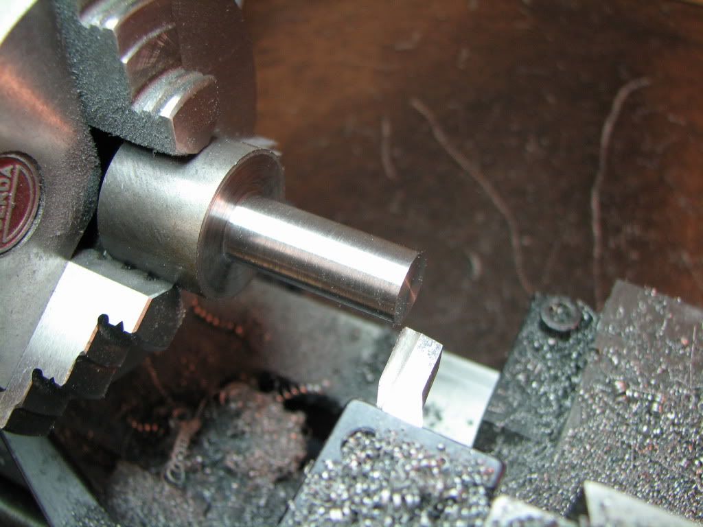
The next step was to turn the larger diameter so that it could be used to indicate the center when the part was flipped. After flipping, the part was trimmed down and the pilot carved.

It was at this point that one or two people (read old farts) got up on the rooftop and discussed the merits of not separating parent stock for as long as possible.

Well you can't argue against such good advice but this old fart (me) feels a need to get up on his rooftop and knock a few people off. :big: Had the parent stock been kept and the flange squared off...then the turned larger diameter would no longer be available for indicating. (It doesn't help that had I stayed with the original piece of stock...there wouldn't have been any parent stock to talk about.)

Had I followed through enough with Marv's advice on machining sequence as well as tel's advice on turning down to nearest available collet size...well...I'd be all alone on this rooftop. ;D (Not that I want that...depending on how pretty these guys are...that might be my loss.)

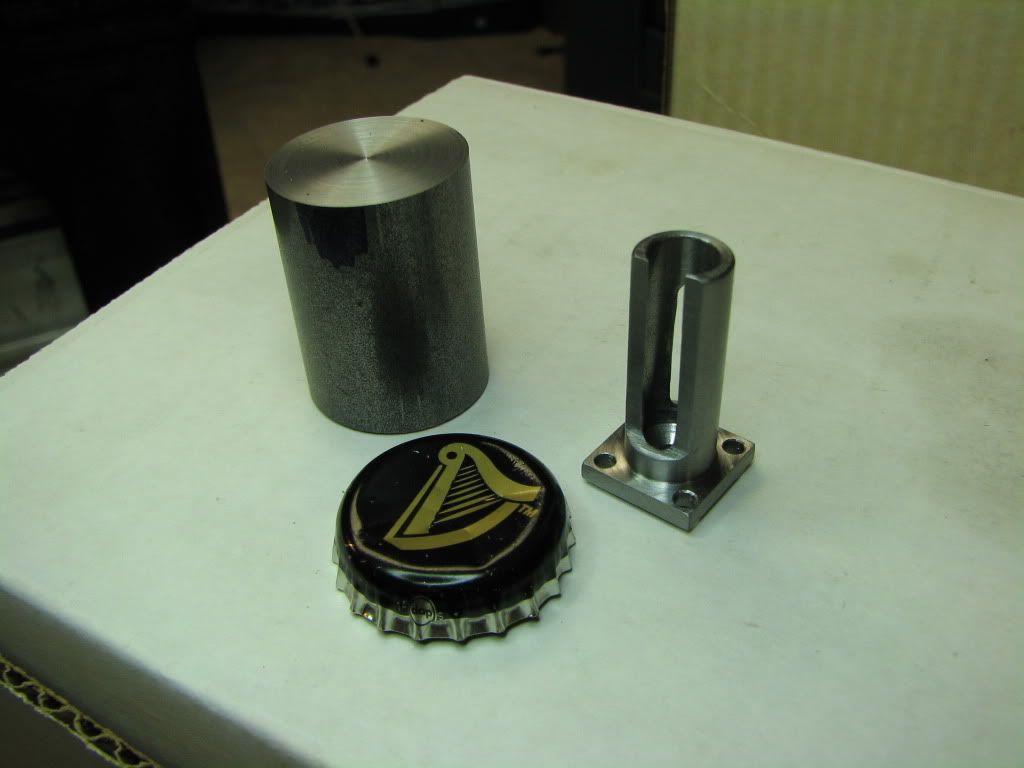
So here's the part after trimming and carving the pilot...

IMG_4464.jpg


The piece of stock to the left is the original 1018 that seemed to me to be a tad short. I do like that 12L14 stuff.

I wrapped it in aluminum and put it in some V-blocks in the vise. Squared the flange and drilled holes.

IMG_4465.jpg


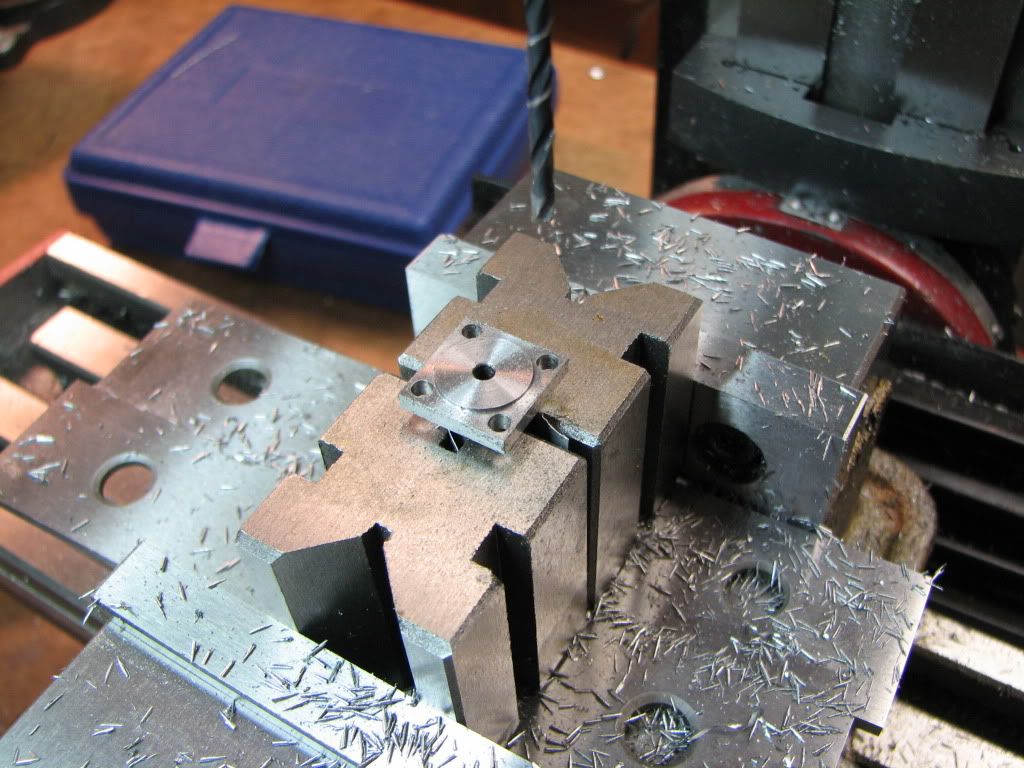
I think this turned out better than the cylinder cover but it's still a little off. Shouldn't matter so long as the pilot is right. The clearance holes should be okay.

The bigger problem now is milling the two windows. The drawing shows a 0.03 radius at the corners of the windows. To me this means a 1/16 end mill. But the end mill I have is kind of short...I don't see how this can be done. The 1/8 end mill looks like it can reach from front to back but that means a .06 radius. I suspect this doesn't matter.

Anyway...a job for tomorrow. I shall sleep now and hope my dreams are fart free.
 
tel said:
That said, these off-size specs are a really annoying facet of the modern form of our art, fuelled by the 'automatic' dimensioning of parts in CAD drawings, and the seeming inability of a lot of plan makers to reset the parameters from the (default?) two decimal place resolution to 3 or even 4 decimal places. When. f'rinstance, I'm looking at a plan that calls for a diameter (or length) to be 3/8" then I want to see 0.375 written there, not .38" as is becoming more and more prevalent. PLAN MAKERS PLEASE NOTE!!!!

I hear you, and up you a "hear, hear", on this, Tel. A lot of the stuff I see now days shows the lazy two decimal point dimensioning, and often without any tolerances listed.
And while we're on dimensioning... extension lines that run all over the drawing and into the part line they are supposed to be calling out. What's happened to drafting conventions?

Zee, this piece looks very nice!
I haven't seen the prints you are working from, but I assume there will be a bore inside the smaller diameter of the cross head. If the radius of that bore goes past the edge of the slots with the .03" radius, that is, past the edge of the "window", then your 1/16" end mill may reach in far enough to do one side at a time. Make the bore in the piece, then cut the windows. All the metal in the center will be gone after you bore it. You'll have to do the radii on one side of the window, then turn the piece over and do the other.
You have the square end that you can use to index the two windows.

I could be missing what you're saying about using the 1/16" end mill, but I think if you check it out, this will work.

Sorry about joining the rooftop crowd.
Mind your parent stock.
;)

Dean
 
Is there room up here on the rooftop for me too?

Carl, That is looking good. I have yet to cut any 12L14. Been working with a lot of 1018 CRS.
 
OOOOOOK 'Fiddler', now if you had left a full sized section long enough to do the square bit, and then turned a bit down to the diameter of the bore spigot long enough for holding/indicating/whatever purposes, then you still could have got all of the above with it still attached. The problem you had was one of mindset 'cos you were looking at machining the square while it was in the horizontal plane. Here's a pic of a square being milled on a 'ome made tap - with the whole shootin' match still attached to the parent.


tapsq.jpg
 
Hee hee...seems my woodwork is infested. :big: Nah...this is great.

Thanks Dean. Yeah, the dimensioning has been interesting. I know some of it is me but it irks when I add/subtract dimensions and the result doesn't equal another.

As for milling the windows...you're right, there is a bore. I did think about doing one edge of the window, flipping the part 180, and then doing the other edge. It just seems inefficient (and risky for me). Have to do this twice since there are two windows. I haven't made up my mind yet to do that or use a single setup with larger end mill and have a larger radius.

Twmaster...there's room for all. Having the 12L14 was one of the reasons I had little hesitation to dump the 1018 that came with the kit. The cylinder cover is 1018 and the difference in milling the same shape in the 12L14 crosshead is amazing.

Tel...'fiddler'...good one. Sometimes I feel like that.

I understand I could have held the larger diameter in a collet and milled the flange square (and as ttrikalin says...it's a good tip). But that would also have milled off the reference diameter that was going to be used to face and turn the pilot (which is on the same end). Without the reference diameter I would have to use the square to indicate off of and that means it would have be perfectly milled and placed. I doubt I would be successful at that.

Don't anyone get me wrong...I'm not arguing against the advice that parent stock should be kept as long as possible. (I'm not arguing at all.) I'm just saying that had the diameter been turned down to .4375 instead of .44 then removing the stock when I did was perfectly fine. And, that keeping it to mill the flange before the pilot would likely have resulted in an off center pilot (at least for me).

Let's change the subject and have a party up here! ;D Hm...why do I hesitate to suggest a topic? :big: Anyone have a fiddle?
 
No fiddle. Although by that cap it looks like somebody else got your 'harp'.

:)
 
Since part of the value of this thread is to teach future newbies about machining operations, I think it's worthwhile to try to summarize a proper (though certainly not singular) machining sequence for this somewhat complicated part. Maybe it won't help Zee but it's useful in the long term.

It's been so long since I built this engine that I don't remember exactly what I did. That's good since it means I'll have to totally rethink it.

I'll get the ball rolling by putting together a strawman for the rest of you to shoot at...

Select parent stock at least twice the length of finished part.

Turn rod guide (my name for the cylindrical part with the windows) to an aliquot size.

Bore rod guide to finished diameter. Do NOT drill (1/8") hole through which piston rod passes yet.

Grasp parent stock in collet in (square) collet block. Mill windows in rod guide. In the same setup mill square section into parent stock - allow enough extra to turn cylinder guide.

Cut part from parent stock.

Mount part in lathe grasping rod guide in collet (or in 4jaw, referencing off rod guide OD). Face to length.

Turn cylinder guide. Drill/ream hole for piston rod.

Mount in mill and drill attachment holes in square section.

So shoot away. Tell me what I overlooked or got wrong.

 
For the newbie...

aliquot
Merriam-Webster Online:
Function: adjective
: being an equal fractional part (as of a solution)

I take that to mean the OD should have been 0.4375 and not 0.44. In which case the turned part fits a collet and the flange can be squared and the holes drilled in the vise after turning the other end. Note that had the OD been correct then no extra stock would be required or wasted.

 
So here it is...

IMG_4466.jpg


It could be better. In fact, it can still be made better. But I'm running out of time today...I can still improve it later.

I took a chipped up 1/4" end mill and rounded off the bits. I used that to mill the windows. Came out okay except there was a lot of metal pushed into the part. Then it was filing filing filing sanding sanding sanding. It cleaned up pretty good but I'm a tad worried about how well the piston rod will slide.

Still, the milled flange and mounting holes came out pretty good.

Here is everything I have so far...

IMG_4467.jpg


It's getting exciting. But don't be surprised if I end up doing some parts over ;D
 
Looking great, Zeep! Looks like the part matches the drawing, which is all that really counts. So, what's the NEXT step in this project?
 
I take that to mean the OD should have been 0.4375 and not 0.44. In which case the turned part fits a collet and the flange can be squared and the holes drilled in the vise after turning the other end. Note that had the OD been correct then no extra stock would be required or wasted.

Yes, that's what 'aliquot' means. In fact, it's worth one of my all-caps rules...

WHENEVER POSSIBLE, MAKE PARTS IN STANDARD, ALIQUOT SIZES TO FACILITATE WORKHOLDING.

You still need that extra parent stock so you have something to grab onto *securely* while turning the rod guide and milling the windows and square section.

If you're making small models/objects, such leftover lumps of parent stock aren't wasted. Keep them in a bin, separated by metal type, and use them in the future for even smaller parts, spacers, standoffs, etcan. In my shop the rule is:

It isn't discardable scrap until it weighs less than five grams (the weight of an American nickel coin).

Oh, that "metal pushed into the interior of the rod guide"... A tip...

Keep your buggered reamers or junky ones found for nothing at yard sales and use them as bore cleaning tools for situations like this. While useless for sizing holes, they're usually still sharp enough to operate as satisfactory deburring tools.
 
zee............looking good, i should be a nice runner soon.

marv: thanks for the tip on the reamers

chuck :)
 
mklotz said:
You still need that extra parent stock so you have something to grab onto *securely* while turning the rod guide and milling the windows and square section.

For anyone following in my footsteps and using the instructions that come with the kit...the instructions have you set the squared flange on a parallel while you pinch the part in the vise and mill the windows from the side. I had two issues with that...for one they don't have anything on the other side of the vise...but that can be taken care of with scrap and shims...but I was really concerned about the side force (or top if you mill from the top like I did) on the end that had no support. A stop block might not be a bad idea for milling from the side. A shimmed support from underneath if you mill from the top.

mklotz said:
Keep your buggered reamers or junky ones found for nothing at yard sales and use them as bore cleaning tools for situations like this. While useless for sizing holes, they're usually still sharp enough to operate as satisfactory deburring tools.

I did consider doing that. I still may if I run into a problem fitting the piston rod. Thanks for adding the tip.

Just saw your post chuck...thanks.
 
Ah...Vernon...the next step you ask?

I'm thinking the piston and piston rod.

Let's see...
The drawing shows the piston should be 0.56 by 0.25.
Would the aliquot size be 0.5625 (9/16) or even 0.546875 (35/64). ;D
The material called for (and that they provided) is 5/8 round by 0.38.
The cylinder bore is 0.500.
Good to go!

Wait a second...

Something...not...right...pain...behind right eye...it hurts...

0.56! Typo? But then why the call out for 5/8 round?
3/8 to 0.25? What am I going to hold onto?

Aw forget it...in fact...forget that crumb of metal entirely and see if my six inch hunk of 0.5 will do the job. That, or the six inch hunk of 5/8. Either way, I can chuck the whole thing, trim and fit to size, then part it off.

Yeah...that's the ticket.

Now to go take apart the cylinder.
 
... a fine tin roof with real wooden floors be-loooow ....

I had two issues with that...for one they don't have anything on the other side of the vise...but that can be taken care of with scrap and shims...but I was really concerned about the side force (or top if you mill from the top like I did) on the end that had no support. A stop block might not be a bad idea for milling from the side. A shimmed support from underneath if you mill from the top.

Here y'go, take a time-out and make one, no make about a dozen of these, in different sizes

http://homemetalshopclub.org/projects/machinest_jack/machinist_jack.htm

 
Oversize is GOOD Zee. Here's some stock for 5.5mm a/f nuts that I whittled down from 3/8" rod


reduced to hex.jpg
 
tel said:
... a fine tin roof with real wooden floors be-loooow ....
I'm glad I'm not the only one with that song in my head. ;D
 
Yeah, a 0.56 piston in a 0.5 bore is going to seal like crazy though the friction is going to be a bitch.

I'm tempted to say something about the plans, instructions and supplied stock but my natural aversion to sarcasm prevents me. Yeah, right! :)

Here's a little preemptory hint for the piston...

Elmer's plans usually call for a few oil grooves in the piston, generally made with a pointed tool. If you turn the piston to size and then make the grooves, the grooving operation will throw up minute humps of metal that must be smoothed away before the piston will fit again in the bore.

Make the oil grooves when the piston is, say, five thou oversize. Then the final sizing cut on the piston will remove these humps and leave a nice, truly cylindrical surface.

BTW, congrats on beginning to see the wisdom of forming parts on large pieces of parent stock. Remember to cut your piston long enough (say 3/8") on the parent stock to allow room for the cutoff tool/bandsaw blade to free it.
 
Machinist jacks are a great idea tel. The ones I made are too tall but it does make me think I'll add some more of those kinds of things to my tool project list.

No problem having oversized material. My main point was that the drawing is just wrong. Both in dimension and material callout. Had one gone the other way and made the piston first with the idea of sizing the cylinder to fit...they would have been in for a rude surprise.

Ah Marv..you posted while I was writing this.

Thanks for the tip on the grooves. I didn't recall any grooves on the piston so I looked at the drawing again. None there. So I looked at the assembly drawing for the piston and rod. Yep...there's the grooves. (And an outer dimension of 0.563...even bigger than the drawing for the piston by itself!! Ha!)

Yep...wanted to make it long enough too so that when sizing the cylinder, the piston would go in deep enough rather than just barely in.

Thanks.
 

Latest posts

Back
Top