Horizontal Mill Engine From Kit

Home Model Engine Machinist Forum

Help Support Home Model Engine Machinist Forum:

This site may earn a commission from merchant affiliate links, including eBay, Amazon, and others.
zeeprogrammer said:
Foozer!...Welcome back. What happened to your avatar? Lose it on the road trip? Watcha been up to? Watcha going to be up to?

Avatar was a tad bandwidth happy, got ta make another little less in the moving parts bit.

Little thousand mile road trip tp Sac, Ca. just a there and back for no reason. Kinda stopped at every rest stop along the way to check out the scenery and have a reason for the trip. Hmm is that a reason?

Getting too cold for barn work, If i.m real sweet on the Bride, she may let me move the lathe into the house. Ah such are the dreams of mad men

You coming right along fancy with your project i see. Lot less "Wall of Shame Learning" objects. Good work Zee

Robert
 
Very good going Zee Thm: - And like Marv said on the instructions :)

Rof} Rof} LOVE THAT SONG!

Regards, Arnold
 
Thanks shred, kvom, marv, foozer, and arnold.

In thinking some more about this, it indeed would have been better to do the pocket first. Mill sides square, mill pocket, part it off, then put in vise upside down to mill to size, and then put in deeper into vise for slotting.

As can been seen, there's several viable approaches.

The slot for the adjusting nut is 0.135. The other slot was supposed to be 0.11 but I made it 0.125.

If I'd thought too much for myself...I'd probably be shy a finger or two. I listen (or read) from supposed experts (i.e. the instructions) until I develop enough skill and confidence to experiment.

But to your point Marv...it IS rewarding when, after having developed those skills and confidence, you can move forward on your own.

The song was fun...maybe I should try a poem sometime. ;D

Ah Robert...you haven't read the entire thread then. The ratio of good parts to bad parts is still 1-to-1 so my Wall is still increasing at a good pace.

Checking out scenery is an excellent reason. Hope you had a good trip. Also hope you get the lathe moved and can have some machining fun during the winter.

 
And speaking of my ratio of good parts to bad parts...here's the next good:bad part...

IMG_4456.jpg


I need to get a better setup for picture taking.

This is the Slide Block.

The bad part (aw c'mon...it's the one on the right) is the one I snapped the tap in.

A good pal sent me a little box of goodies...one goodie being an engraving tool that I used to mill the 45 degree angles. He also sent me a 1/32 end mill which I need to continue the Porting Plate.

And yes...he's the same guy that sent me that bottlecap you see in the picture. The same guy that sent me a paper model of a beer. The same guy who owes me beer and is now (along with Marv) immortalized in song.

Thanks Vernon. ;D


The song was fun...maybe I should try a poem sometime.

Mendelssohn made himself famous with Die Lieder ohne Worten. Take him as your model.

Poetry? I like cheery, upbeat stuff like this...

Razors pain you;
Rivers are damp;
Acids stain you;
And drugs cause cramp.
Guns aren't lawful;
Nooses give;
Gas smells awful;
You might as well live.

-- Dorothy Parker
 
Dorothy Parker!!! Great one Marv. That brought back some memories when I met my wife. Thanks!

And here's another part...

IMG_4457.jpg


This has changed my ratio of good to bad. Nothing to the right of it. Nothing to the left of it. And to quote another famous mammal ;D, "Nothing up my sleeve". No bad part! (No fair counting the part you see!!!)

However...this does not mean that more do-overs of already made parts are not in my future. You might not be able to tell, but the hole is not on center top to bottom. This is an attempt to account for the valve being 0.02 short. My hope is that by making the nut 0.02 bigger below the hole, it will set the valve at the correct spot on the port cover. We'll see. To be honest...I have no idea if it even makes a difference.

 
That nut floats in the D-valve. The valve is free to move (slightly) up and down on the nut. This is so the valve can be pressed down by the steam/air pressure to create a better seal. Since the valve pocket is always over the exhaust channel (at atmospheric pressure) and the top of the valve is exposed to the (higher than atmospheric) pressure in the steam chest, the valve is always pressed down against the valve plate by the pressure differential because it's free to slide on the valve nut.
The animation at:

http://www.animatedengines.com/locomotive.shtml

shows what I'm talking about.

The net effect is that, *within reason*, it just doesn't matter where the hole in that nut is. If, however, the hole misplacement causes the nut to ride against the steam chest cover, thus creating friction, that will have to be fixed.
 
Thanks Marv. Good to know and very helpful.

I've seen that site before and it's very helpful to people new to steam engines (like me).

No problem as far as the steam chest cover. The hole wasn't misplaced...that is, I didn't move it relative to the top of the nut. The distance form hole to top of the nut is as shown by the drawings. I just added another .02 to the total height of the material and made sure it was all at the bottom.

 
zeeprogrammer said:
Ah Robert...you haven't read the entire thread then. The ratio of good parts to bad parts is still 1-to-1 so my Wall is still increasing at a good pace.

Checking out scenery is an excellent reason. Hope you had a good trip. Also hope you get the lathe moved and can have some machining fun during the winter.

Shes brib'able :)

got my own wall of shame item. Changed the cam in the car before took trip and used that synthetic oil, ah WRONG, not with flat tappets (SBC) Time for another cam change as number 3 exhaust is flat as an unleavened biscuit. But the trip down the coast hyw was fun, refreshing and way over do.

Ah your going gang busters, just watch the over confidence factor, well its gonna happen anyway, just ride with it.

Robert
 
Another part and a half! A cylinder.
We won't talk much about that 'half' a part. Poor job drilling the cylinder hole.

So here it is...

IMG_4459.jpg


Rather than drill the cylinder, I bored it after drilling 0.25 and then 0.34. The instructions had you do the bore first but I remembered what happened when I did the launch engine...drilling and tapping the holes around the cylinder hole might have caused bulges.

I had two scares during this...one was when the air compressor went off (I'd forgotten to turn it off and it leaks a bit). There's a slight dent in the drop-down ceiling above me now. The second scare was during the sanding of the cylinder. I noticed it wasn't completely square...it had a slight tilt to it. I don't know what I did wrong but I was really lucky. The tilt was to the side. So I put it in the mill and shaved off the ends using the flycutter. Maybe .005 to .007 on either end. This left the part usable and looking good.

Almost had a couple of 'aw rats'. One was usng a steel ball bearing as a tooling ball. I almost didn't take into account the diameter of the ball. Even worse...the process required tilting the part at an angle and I almost set the angle wrong. It wasn't supposed to be 58 but 90-58. I used angle plates.

Here it is is with some other parts trial fitted...I haven't polished the cover or valve port and the hose couplings could use a better polish too.

IMG_4460.jpg


Still have about 9 or 10 parts to do and a few to finish up.

I love this time of year except for one thing...the wildlife likes to find warm places...I'm in the basement...several spiders...a snake went by my foot the other week...mice in the drop-down ceiling the other night (they were really going at it)...had a bird a couple of years ago (no idea how it got down here).
 
Looking very good. At this rate you'll be done very soon.

Even worse...the process required tilting the part at an angle and I almost set the angle wrong. It wasn't supposed to be 58 but 90-58.

That's all too easy a mistake to make. DAMHIKT. After constructing an angled setup, I always sanity check my work with one of those digital angle gages. Before I had one of those I used to use one of those analogue types with the weighted pointer and angular scale.

http://www.use-enco.com/CGI/INSRIT?PMAKA=990-0202&PMPXNO=3009508&PARTPG=INLMK3

The digital one takes up much less headroom so it's preferable.
 
arnoldb said:
That's really looking good Zee Thm:

I second that ,,,,,,,,,,,,,,,nice one Thm: looks like you will be finished in no time

Regards Rob
 
It's really starting to look "enginey". ;D Congrats.
 
Heck yeah, Zee! Looking very good.
What kind of coin is that in the picture?

Dean
 
Nice progress, Zee. Love the running commentary! You should've been a writer (or maybe you are?).

Chuck
 
Thanks Marv...yes I hope to be done soon...in fact...I should be done in week 23...whenever that is. ;D

Thanks Arnold, Rob, and Vernon.

Thanks Dean. The 'coin' was a gift...worthless maybe...but we have to consider both the giver and the recipient. ;D

Thanks Chuck. Glad you like the commentary. Nope...not a writer...just of 0s and 1s and some text to explain them. ;D

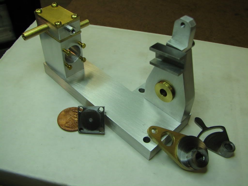
Well here's the next part. Not very good. I rushed it and this resulted in the holes being a tad out of place (not to mention the original part getting trashed). For a replacement I used a previously mangled crankshaft.

Turned it to size and made the 0.025 pilot. Then went to the mill. This could have been a better job. I probably should have made a dent in the part while it was on the lathe and used it in the mill to find the center of the part. Then moved out to drill the four sides. Instead I eye-balled the center using the edge finder. Not good practice but close enough. (I thought about using a wiggler? but I think it's too low a quality to work well enough.) The downside is that any error was compounded by the next operation. I used the vise stop I'd made some time ago. Found where I wanted to put the hole in one corner and then rotated the part to drill each hole. While not critical, I can't say I'm happy with my methods.

Anyway...here's the part...

IMG_4461.jpg


I had no idea it was this small.

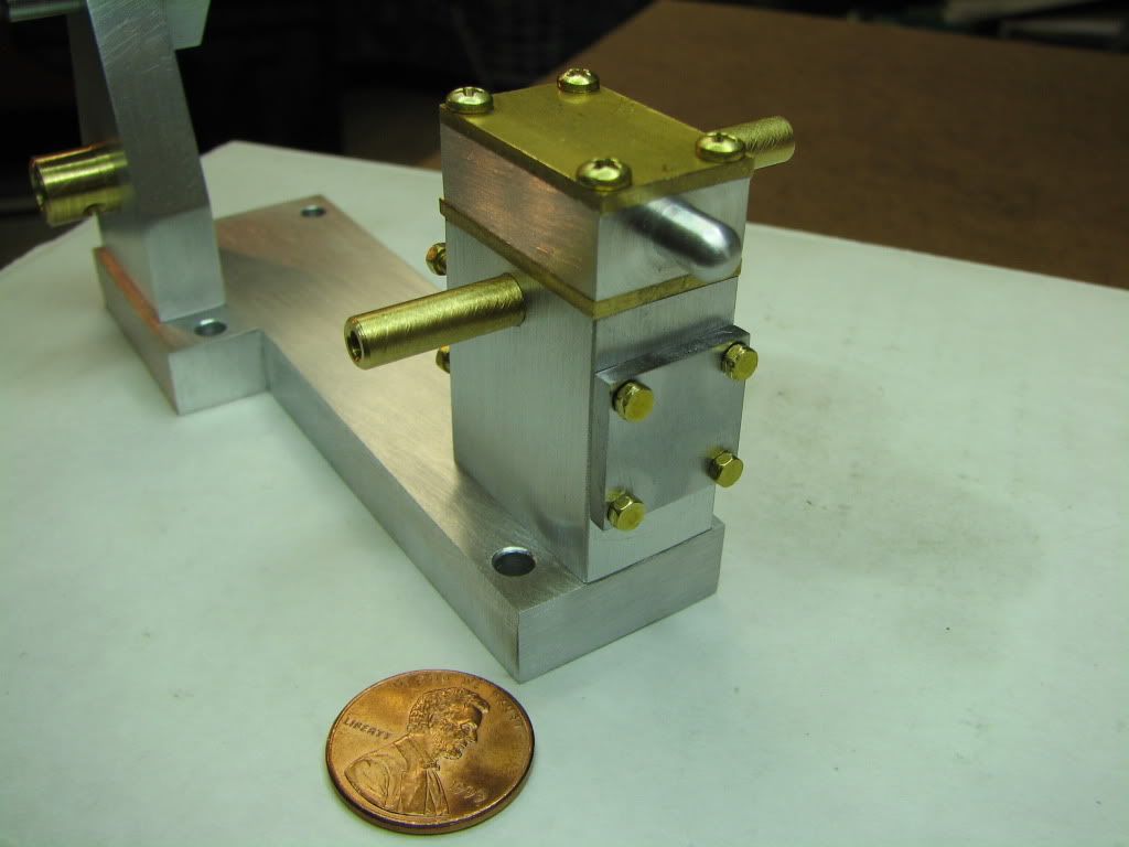
Here it is temporarily mounted on the back...

IMG_4462.jpg


I nearly destroyed one of the bolts trying to put it in with the cover. So I stopped, found a 2-56 with a socket head and screwed it into each hole to kind of clean it out or work the threads a bit.

Then I used a paper towel and some small pliers to screw each bolt. Tedious and subject to slip.

What do you use to screw such small bolts in? Miniature spanner? Made a tool? And what do you do to protect the finish of the part being bolted?

Thanks.
 
:bow: :bow: :bow: :bow: :bow: i must have missed some bits :bow: :bow: looking great ZEE

Regards Rob
 
mklotz said:
My wife has always told me that I would achieve some small measure of fame in my lifetime. I just didn't realize how small it would be when it finally happened.

Just take what you can get Marv ;D :D ;D

Zee ................. looking good dude 8)

CC
 
I saw an article somewhere, and the author used the head of a socket head capscrew. He welded or silver soldered it to a bar and then ground off the threaded portion macking a small wrench. Looked like a great idea for those little hex bolts.
Bryan
 

Latest posts

Back
Top