Horizontal Mill Engine From Kit

Home Model Engine Machinist Forum

Help Support Home Model Engine Machinist Forum:

This site may earn a commission from merchant affiliate links, including eBay, Amazon, and others.
You did that pocket gooood, Zee. The whole part looks very nice!

Glad there's no new song. I almost had the old one out of my peanut brain until you mentioned it...

Dean
 
The pocket looks great, and the final part looks perfect.
I cant wait to see it attached.
-B-
 
SWMBO dragged me out of town for a weekend but I'm back now.

First issue was supporting the part while drilling the four corner clearance holes. Instructions showed parallels...but if they weren't thin enough...the drill would hit them. So I used two tall parallels in the center, a bit of foam, and a shorter parallel at each side. Then made sure I didn't drill too far.

Sit chest on sacrificial plate supported by parallels.

or

Make sacrificial parallels of aluminum.

or

Make stepped parallels of aluminum... Two pieces of ~1/4" plate milled flat, clamp together in vise and run a 1/8" endmill down the line where they abut. Result is stepped sacrificial parallels

or

Buy set of cheap 1/32" thick Chinese parallels from Enco. Every modelmaker needs a set of these.

Did you remember to mill clockwise around the chest opening so you weren't climb milling?

The only question I have is whether I got into the tenon far enough with the drill.

I generally drill the hole after milling out the cavity. That way I can touch off the drill tip on the inside of the cavity and get a clear zero for the depth measurement. Although this violates my rule of "drill first, then mill", in this case it saves one the agony of deep hole drilling with a small drill and allows a more accurate zeroing as mentioned.

The chest looks great. But next time I hope you'll start with a rectangular blank so you can get comfortable with centering stuff like that in the 4J.
 
Don't pay Cedge no never mind....... Grin

I agree whole heartedly.... that Cedge guy can be a PITA....LOL

Nice going Zee.... beginning to see you peeking outside the box?

Steve
 
Thanks very much all. The support is fantastic and it means a lot.
This is great fun....just really great fun.
Thank you.
 
zeeprogrammer said:
IMG_4431.jpg


The pocket came out 2 or 3 undersized in width and within a thou of length. Similarly for the outer dimensions. The only question I have is whether I got into the tenon far enough with the drill.

Aha! So that's what it was - I was trying to get my head around just what you were doing when you were having trouble a few pages back. Still, you won thru' in the end, and very nicely as well.

That said, I never carve steam chests out of the solid like that, but put the stuffing box and tail piece (if any) in as separate pieces, silver soldered it. OK, you are using aluminium, but that could be either threaded together, or use a light press fit and a cross stake. Something you might like to try some time further down the track.

steamchestsss.jpg


steamchests2.jpg
 
Thanks tel. I remember those steam chests from your own thread.

Well...somehow I managed the valve for the steam chest. (Actually won't know until I put the engine together.)

The instructions (there's that word again) talked about a piece of stock that had 5/8" extra length for chucking. The part that came with the kit didn't. Itty bitty thing about .375x.375x.31. I could not get my head around how to mill the thing and keep it square. Instructions put it in a vise...sticking out the side. Milled the four sides, the end, then used a saw to make the two slots. I couldn't figure it out. Clamping on the unmilled chucking material (had there been any) could not have kept it square.

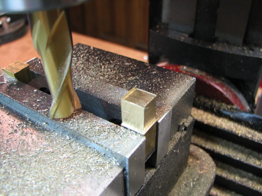
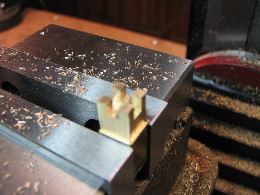
So I got some advice. I ended up cutting a new piece of stock from some .375 square bar (resulting in the question about the band saw) that was about 5/8 longer. Then I put it in the vise (with a piece of scrap on the other end - which the instructions failed to mention). I milled the four sides...

IMG_4444.jpg


And then milled the top. Then I milled the slots. One of the slots was supposed to be 0.1". In looking at the assembly, I couldn't understand why it was smaller than an 1/8" mill. No need for it. So I made it 0.125.

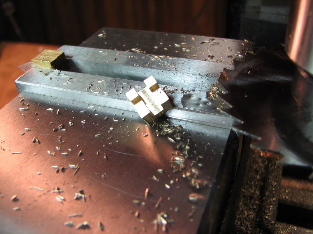
The bad news is that when I went to mill the first slot...I saw I was off by about 0.03" from center. I had used an edge finder to get there. Did it twice and was still off. I think I have a major issue with the mill. Not the tram...but the edge finder is used with a chuck and the spindle is much higher. When bringing the head down for the 1/8" end mill...it didn't stay at the same X,Y spot. I didn't want to get into this right now. I have plans to break the mill down and do it up after the project. So I put the edge finder in a collet so that the Z distance (and error) would be much smaller. Not perfect. But it should work.

That's right folks. Zeep has come out of the box! (But I will scurry back on occasion.)

IMG_4445.jpg


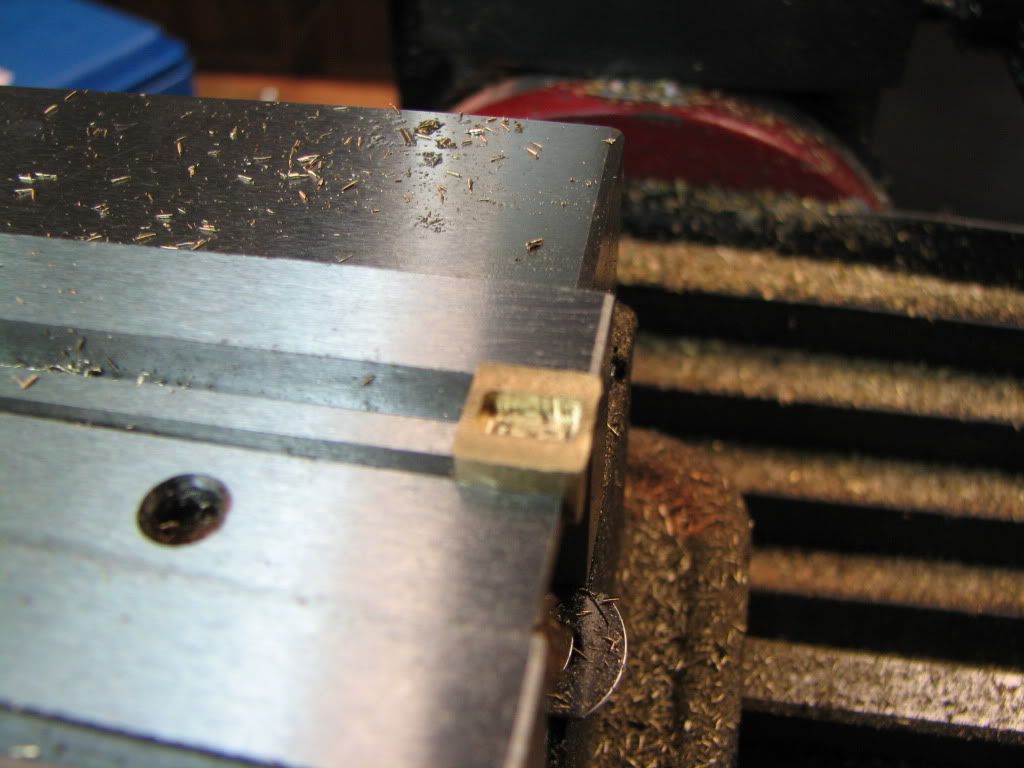
Then I used a slitting saw to chop it off.

IMG_4446.jpg


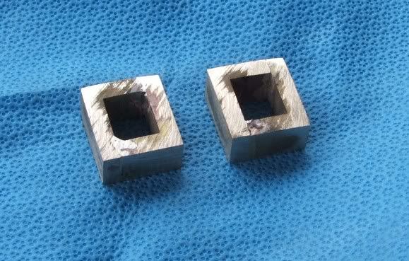
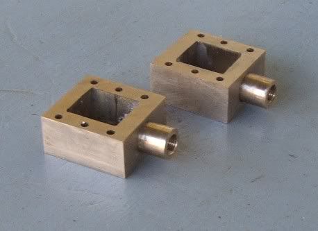
Then flipped it over onto some parallels, milled the top to size, and then milled the pocket.

IMG_4447.jpg


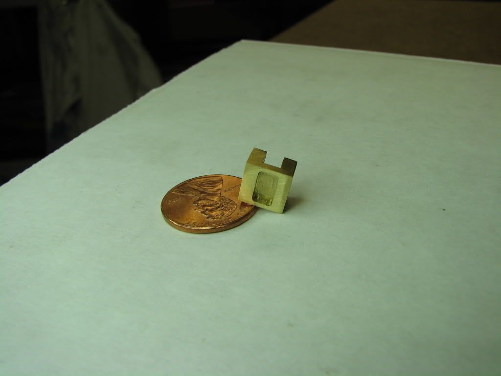
That could have gone better. But only if I'd been a better and more experienced machinist. The height turned out a little shy of 0.25 and the legs got mashed a little. I was able to correct the legs...but still. Also, still need to improve accounting for backlash. You can tell the pocket is just a little off.

IMG_4454.jpg


IMG_4453.jpg


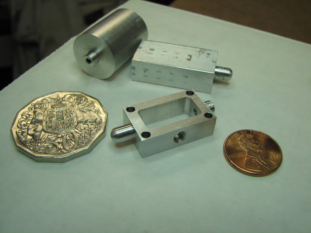
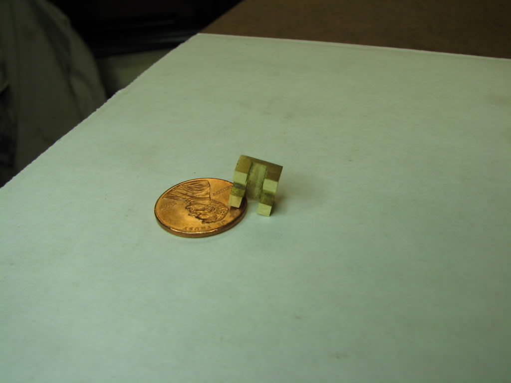
I used a penny. A stationary M&M in this house is unheard of.

[EDIT: Rats. Took a look at the posting. The pictures are a little blurry. The part actually looks pretty good.]

[EDIT: Managed some better shots.]
 
Hey, that thing looks just like what those kind of things are supposed to look like!

Yer doing awright, Zee.

Dean
 
Funny that Dean! Wife got home from a trip and I showed her my new part. All she could say was ..."that looks like a real thing". Thanks.
 
I can't help myself...it's time for a song...

To the tune of 'On Top Of Spaghetti'...

Everybody SING!!!...

On top of my tool post
All covered in swarf.
There sat my good flywheel
When somebody coughed.

It rolled off the quick change
and dented the ways.
And then my good flywheel
Went rolling away.

It went through some portal
and like any good hound,
I chased and chased it
But it couldn’t be found.

I used Marv’s great programs,
he’s such a great guy.
I made a new flywheel
Cause he hates me to buy.

And Vernon’s a big help
His wife says he’s dear.
But he’ll continue to owe me
’Til he pays me that beer.

So if you do machining
And know a vise is a vice,
Stay on Rick’s forum
And heed their advice.

The end.
.....
No need to say anything...you'll just make me cry.
 
Zee
To quote Dr. Hook.....
Awwwww maaaaannn ....Thasss beautiiiful!!

Steve
 
Yep, I can see him now, on the cover of Rolling Stone. ;D
 
zeeprogrammer said:
I can't help myself...it's time for a song...

To the tune of 'On Top Of Spaghetti'...

Everybody SING!!!...

On top of my tool post
All covered in swarf.
There sat my good flywheel
When somebody coughed.


I come back from an extended road trip and find Zee has . . .
Maybe a double shot of tequila and I too might be singing da song


This is way past Hooked on Milling


Robert
 
Steve...Dr Hook. Well that reference took me down memory lane for a while. Spent some time listening to youtube. That was great. I hadn't heard that group in years and years.

Vernon...yeah...is a great song.

Mike...Mr. Zee is reserved for my Dad. Only boys calling on my daughter can call me that. You're not calling on my daughter are you? Are you? I don't want some model engineer calling on my daughter. They're no good. They're only interested in their little engines. ;D

Foozer!...Welcome back. What happened to your avatar? Lose it on the road trip? Watcha been up to? Watcha going to be up to?
 
The valve came out fine, but I would have done the milling in a different order:

1) mill the block to finish dimensions

2) mill the bottom pocket

3) Cut the cross slots

No danger of mashing the legs that way.

You should be getting close to having a runner it seems.
 
Thanks kvom.

Not sure about that though. To do the pocket would have meant removing the material that was being used to hold the part in the vise. There wouldn't be a lot to hold onto when doing the slots. That's actually why I felt I had to leave the instructions. I couldn't figure out how to hold onto the part.

One of the slots was dimensioned to be .11 and the other .135. The .11 slot I had widened to .125. I'm thinking it would have helped to use that slot and sit the part on a 1/8 wide parallel and clamp on that.

As for being close...I still have some 14 parts to make. At my rate, that should provide at least two more songs to abuse this forum with. :big:
 
You could bury the part in the vise jaws, cut one slot the length of the vise, rotate the part 90 and cut the other slot. You have to worry about collapsing the part with too much vise pressure, but then you have more to hold onto. I did that on at least one Elmer's Engines valve.

 
If you cut the slots in the Y direction, against the jaws, then you need a lot less clamping pressure. That applies to most milling with small parts. Shred's method is also good.

My main point is that it's a lot easier to hit the desired dimensions when you're working with a bar.
 
Congrats on departing from the evil instructions. How was it? Intoxicating like your first vodka? This thinking for yourself can be addictive so be careful.

Your valve looks fine and should work well.

I would have done it just a tiny bit differently. This is a perfect example of my dictum:

NEVER REMOVE A PART FROM ITS PARENT STOCK UNTIL IT'S ABSOLUTELY NECESSARY TO DO SO.

Cut the end of your starting stock to the final size of the D-valve (as you did).

Instead of cutting the slots in the end of this piece, cut them in the side of the piece near one end, said end hanging outboard of the vise.

Flip the stock over in the vise (slots now pointing down) and mill the pocket.

Mill, rather than saw, the part free from the parent stock. Sawing leaves an edge that often must be cleaned up which implies further clamping and the risk of deformation. Milling leaves a finished edge on the part so no further clamping of the part is required.

Sand the working face of the valve with a bit of very fine emory on a flat plate so the valve can seat perfectly on the valve plate.

One slot (probably the 1/8") is for the valve adjusting nut. It needs to be a good sliding fit on the nut. The other slot is merely clearance for the (threaded) valve rod that threads into the nut. Its dimension, within reason, isn't terribly critical.

Ideally, the pocket should be symmetrically placed with respect to the nut slot. But one of the beauties of D-valves is the adjustability offered by the threaded rod and this adjustability can be used to compensate for minor errors in the relative placement of the two features.

Thanks for including me in your song. My wife has always told me that I would achieve some small measure of fame in my lifetime. I just didn't realize how small it would be when it finally happened.
 

Latest posts

Back
Top