Horizontal Mill Engine From Kit

Home Model Engine Machinist Forum

Help Support Home Model Engine Machinist Forum:

This site may earn a commission from merchant affiliate links, including eBay, Amazon, and others.
Keep at it Carl it does get better.
Then just about the you feel you have mastered it
you'll junk parts in the same day and realize the metal
is the STILL the boss.

Machining is very much like playing golf.
How can pi$$ing yourself off on a regular basis
be so much fun?
scratch.gif

Rick
 
rake60 said:
Machining is very much like playing golf.
How can pi$$ing yourself off on a regular basis
be so much fun?
scratch.gif

Rick

Well, one thing about it for sure, you can play golf 'til the cows come home, but no matter how much you whack that little ball around, you'll never end up with a running engine.

"I can hit a ball into a little cup..."

Yeah, that's very nice. I can make an engine that runs on fire!

:)

Dean
 
Thanks Rick and Dean.

Well...so today I got back on the tricycle and worked on a new column.

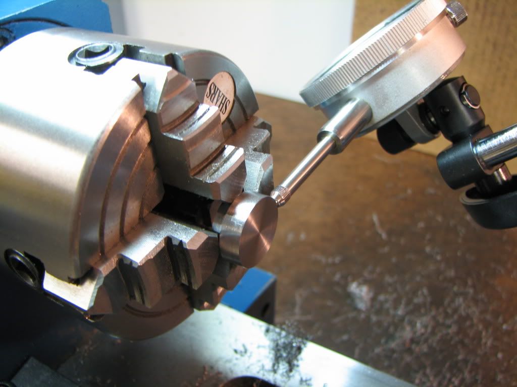
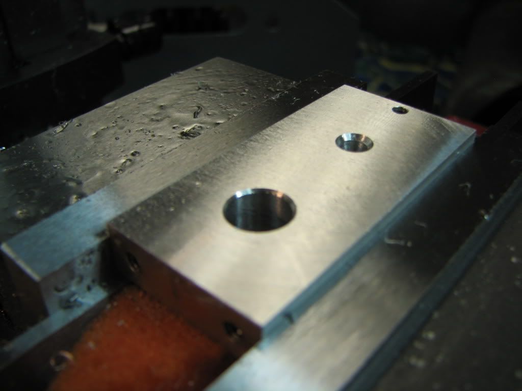
I flycut the two large sides then milled the edges square (I can only hope). Then drilled and tapped the two mounting holes. This time no broken bit.

Then drilled the hole for the bearing. I used the same procedure as before...stepping up in size with the drill...but this time the bearing is loose. I'm hoping some loctite will take care of that...or...a good buddy suggested using a ball bearing or my uglied live lathe center to 'shrink' the hole.

Then I drilled the hole for the tilting slide. Nice fit. Unfortunately I countersunk a little deep but that won't matter and won't be seen.

Then I drilled and tapped the hole for the 'good' crank.

IMG_4372.jpg


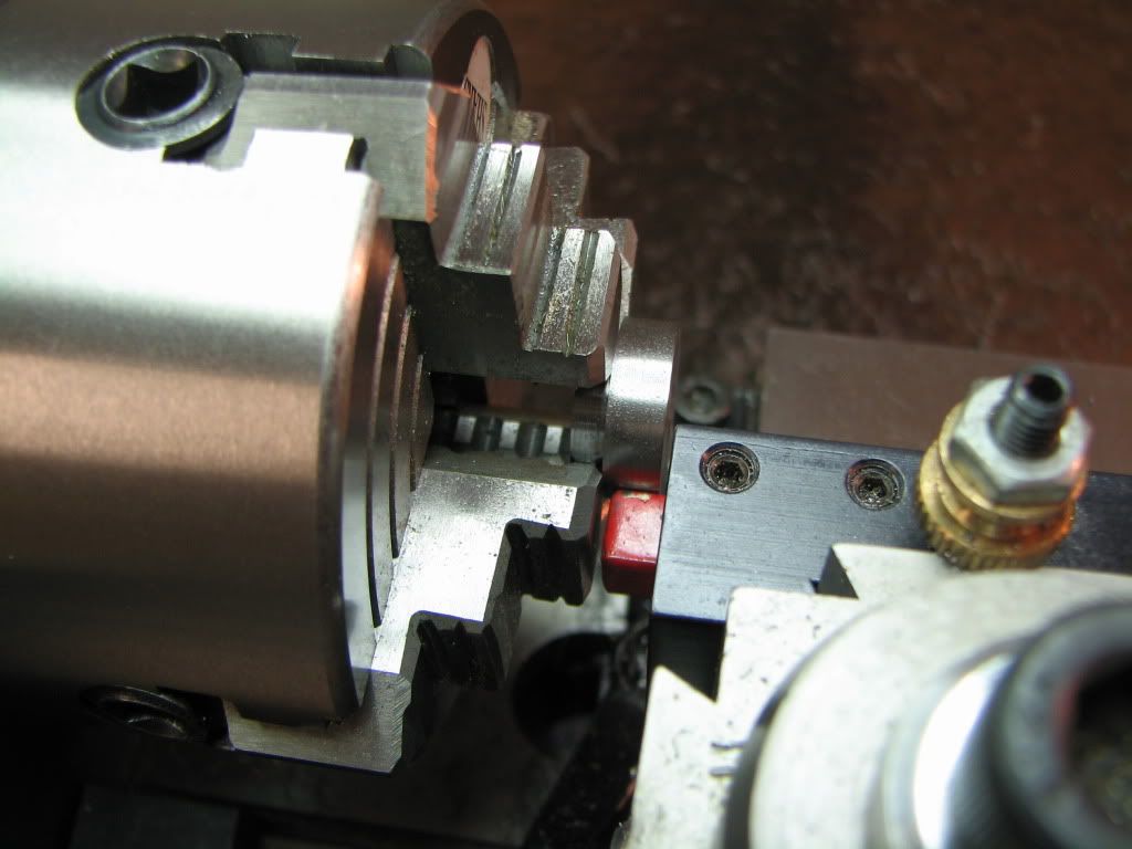
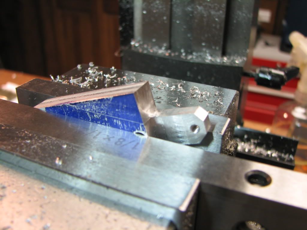
I milled the top of the column and then went for the angled side. As suggested by the instruction manual, I used a parallel to line up the scribe. (There were two parallels to get to the line, then I removed one. The other is held up by two parallels.)

Does anybody see the 'oops' that I'm going to discover? There's actually two of them.

IMG_4373.jpg


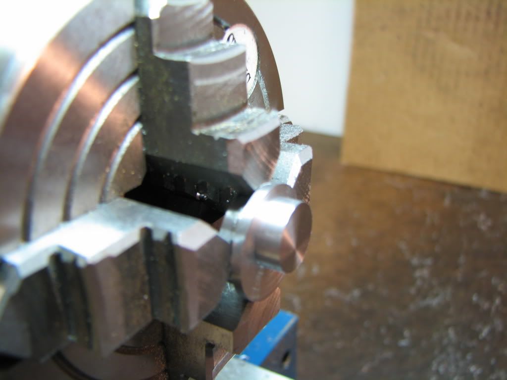
Here it is after milling down the angle. I was really happy with it. I got it to meet the edge perfectly. And then I took it out of the mill and saw the two boo-boos.

IMG_4374.jpg


The one face (where the 5-40 hole is) was milled 1/8 too long! :rant: This was exactly the same mistake I made the other day! I could not believe I'd done it again! I was so careful and remember distinctly turning the crank 8 times for 0.5". And then!!! And then I saw the two 45 degree chamfers on the top were not the same. :rant:I had made the same mistake yet again! Unbelievable!! :rant: :rant:

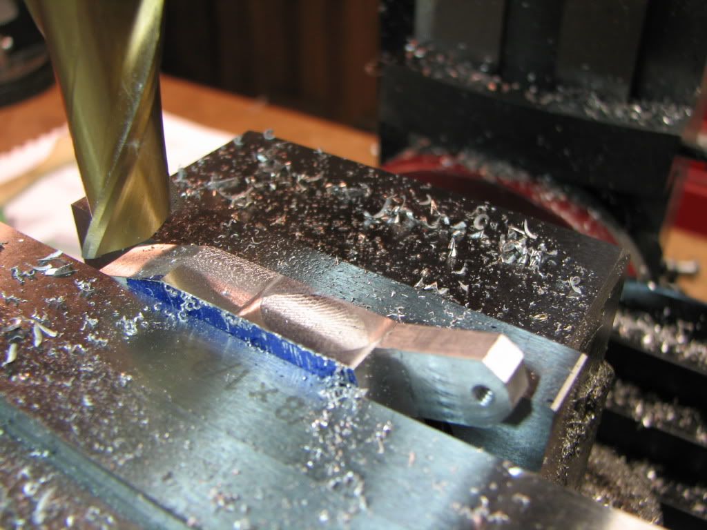
Okay okay. Even though it was ugly...I could still use it. I went to angle the other side. As I lined it up in the vise I looked up. There...sitting pretty...was what I thought was the bad column. It wasn't. It was the good column. With a properly milled face and two perfect 45 degree chamfers. Rof} Rof} I'd put the angle on the bad part. No wonder the boo-boos looked so familiar.

Sheepish just doesn't describe it.

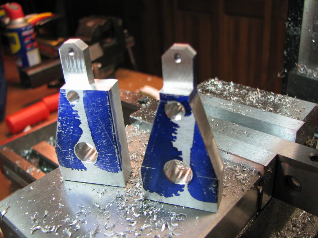
So...put the good part in and did the two angles. Here they are...'ugly' on the left, 'good' on right, 'bad' taking the picture.
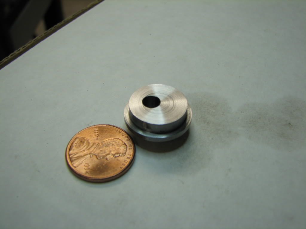
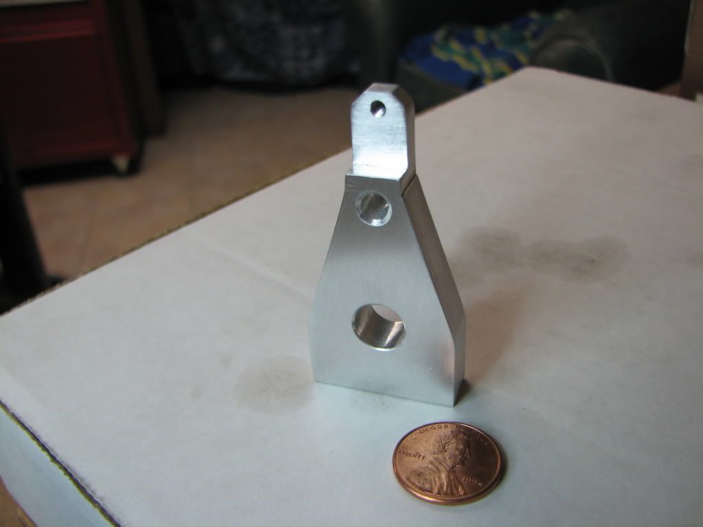
IMG_4376.jpg


All cleaned up...

IMG_4377.jpg


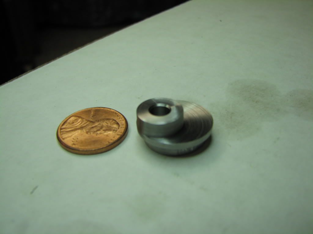
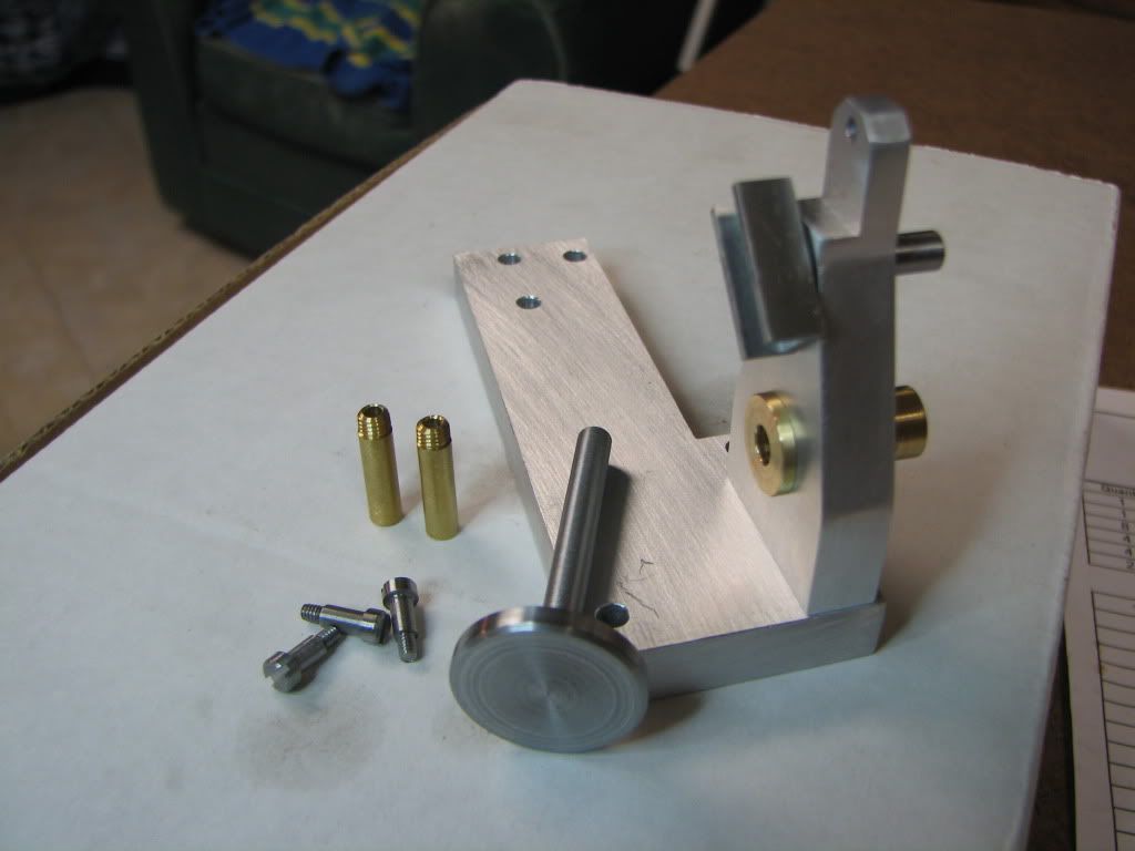
What I have so far...

IMG_4378.jpg


That's right...I still have some work to do on the crankshaft/bearing. The crankshaft used to fit but I think I damaged it somehow. It should only take a light hit with sandpaper.

Geesh...that was one valley I was in for a moment. :big:

 
Wow, that's REALLY starting to look like an engine. Congrats! I won't comment about your angles on the wrong part, since I was "there" when you did it. ;D

That column looks good after you've cleaned off the layout dye and deburred it.
Don't think of the countersink for the tilting slide as being "too deep", call it a pocket for lubricating oil.. or something. ;D
 
Well done for persevering Zeep :D ............. looking good :bow:

CC
 
Good comeback, sometimes mistakes are good.
I have been dying to say that.
-B-
 
Vernon: Thanks. Yeah...feature.
CC: Thanks.
-B-: Glad I could help. :big: But yes...it's amazing how much quicker and better the 2nd (3rd...4th...) time can go.

Working on the eccentric now. Which one I don't know...1st, 2nd, 3rd... ;D
 
I should have said 'trying to work on the eccentric now'...and I now know it's not number 1. :(

I faced and turned the larger diameter on one side then flipped it and put it into a 4-jaw chuck. The instruction manual suggested putting a block of metal in a tool holder and using it to back off .156 from the part and then adjust the 4-jaw to bring the part up to the stop block. I had a couple of problems with that. For one, taking care of backlash was difficult. For another, during the process of moving the part over, it fell out. But that was because I should have been adjusting the other two jaws to account for the slack being created as the part moved from center.

IMG_4379.jpg


So I used the DI instead. :) I mounted it on the compound and slowly, carefully, moved the part over by .156. I constantly tightened and checked the other two jaws to keep the part centered. I did that by just rotating the chuck to either jaw.

IMG_4380.jpg


In this picture you can see the problem. The eccentric is too far in (about .08) from the outer edge. The two edges should have been the same. I was stumped as to what I'd done wrong. I would bet a free coffee that I measured off 1.56 and kept the other two jaws equidistant.

IMG_4381.jpg


I went ahead and drilled and reamed thinking (hoping against hope) that the part would still be usable. I don't think so. This picture also shows another little problem I need to avoid. I don't know how much pressure I should apply to the 4-jaw to make sure the part doesn't fly off. You can see that I overdid it. Not only is the part marred, but there's a dimple on the face. You might also see that the center of the hole is barely .156 away from the center of the larger diameter. It should be .22 (hm...why is my calculator saying .44 / 2 is .2?...hm...a reset fixed it...but that's disconcerting.)

IMG_4382.jpg


But I'm really stumped about being off on the eccentric. As I said, I measured pretty carefully. Odd that the error is about 1/2 of the .156 but I can't see how that plays into it. I checked the diameter and it is the required .44 and the outer diameter is .75.

Well...still keeping the ratio of bad to good at about 2:1. I think the only parts I haven't redone are the 3 screws and the base.

Oh...before I forget...poop. :big:

I saw that kvom!! Yeah...maybe I should have this thread moved to "Mistakes, Blunders, and Boos Boos". :big:
 
My method for making eccentrics...

Face off the end of the stock.

Mount the stock face up in the mill and center under the spindle using whatever technique floats your boat - DTI or edge finder and Osborne (see my page) maneuver. Use the dials or DRO to offset the stock by the amount of the eccentric offset. Use a small center drill to make a small marking hole.

Remount stock in 4jaw. Now, using a pump center, get the small marking hole running true*. Machine the eccentric to required diameter.

With this technique, the accuracy of the eccentric offset will be as good as your mill dials/DRO - no faffing about trying to bodge offsets on the lathe.

--
* I've published this procedure for centering in the 4jaw several times on the forum but, so you won't have to search it out, here it is again. The last couple of paragraphs discuss the making of eccentrics in more detail...

Centering Work in the Four Jaw Chuck

Probably every machinist has his own pet way of doing it. My technique works
for me. Take whatever is useful and modify as you see fit.

To easily center work in the 4J, you'll need to make yourself two tools.
First, make a dedicated holder of some sort so you can mount a dial indicator
(DI) on the tool post (or directly to the compound) with its axis
perpendicular to the spindle axis. Adjust the DI so its plunger is vertically
aligned with the spindle axis. An easy way to do this is to put a pointed tip
on the DI plunger and align the point to a dead center in the headstock. The
idea is to make something that you can drop into place, already aligned, and
lock down in ten seconds or so. Leave the DI permanently mounted to this
holder. A cheap import DI (<$15) is fine since we'll be using this only for
comparative, not absolute, measurement.

While you could use a conventional adjustable magnetic DI holder, I strongly
recommend that you make a dedicated mount that is easily installed and removed.
A general maxim of machining is that you'll be much more likely to do something
'the right way' if setting up to do it is quick and simple. If it isn't you're
much more likely to try some half-a$$ed setup that doesn't work and ends up
damaging the tool, the work, or, worst of all, you.

The second tool to make is a clone of your 4J chuck wrench. We're going to be
adjusting two jaws at a time and it's infinitely easier to do if you can move
both jaws in and out in concert without having to swap the wrench from hole to
hole. It's another example of the maxim I mentioned above. The clone wrench
doesn't have to be anything fancy. Machine a square tenon to match the
existing wrench on the end of some suitable stock, and drill for a press-fit
cross bar. Use your existing wrench as a guide for dimensions. I've found
that, if there's not a lot of room on the back side of the lathe, making the
clone somewhat shorter than the supplied wrench is a good idea.

Ok, now for the procedure. Mount the work in the 4J and roughly center -
either by eye or by using the concentric circles scribed into the face of most
4Js. Snug the jaws down so the work is held securely. Turn the chuck so one
jaw is at the nine o'clock position as seen looking from the tailstock down
the spindle axis. Use the cross-slide to bring the DI up against the work and
reading about the middle of its range (e.g., about 0.5" on a 1" DI). Turn the
scale on the DI so its needle indicates zero. Now swing the chuck through 180
degrees. Unless you've got an impossibly good eye, the DI will now read
something other than zero. (For an example, let's say it reads 0.038.) Turn
the DI scale so the zero is halfway to this reading. (Move the scale so the
needle points to 0.019.)

Now, insert both chuck wrenches and adjust the jaws so the DI needle points to
zero. Swing the chuck 180 degrees and check the reading - it should be close
to zero.

[Aside: If the part you're centering has the same dimension in both jaw axes
(i.e., it's not rectangular), the DI zero you established above will also be
the zero for adjusting the other two jaws below - another advantage of this
technique.]

Repeat this entire process for the two other jaws. [What we're doing here is
treating the 4J as two two-jaw chucks. We can do this because the jaw pairs
are orthogonal and, to first order, adjustments of one pair will have very
little effect on the setting of the other pair.]

If you've been careful, the total runout on the part should now be only a few
thou. Depending on your esthetics and the part requirements, this may be good
enough. If not, repeat the entire process until the runout meets your needs.
After centering, check to ensure that all the jaws are clamped down tightly.
It's easy to leave one loose. If you have (left one loose), you may need to
rerun the centering procedure after you've tightened it.

With this procedure, you should be able to center something to +/-0.001" in
ten minutes on your first try. With not much practice, you can get that
number down to one or two minutes. Soon your three-jaw will be gathering
dust.

One of the most common uses of the 4J is for drilling/boring offset holes in
eccentrics (i.e. cam drivers for model engines). In this case, you aren't
centering the stock itself (as we were above) but rather need to center the
location of the hole.

First centerdrill the location of the hole in the milling machine. Mount the
stock in the 4J and roughly center this centerdrilled hole. [A fast way to do
this is to use the pointy end of an edge finder held in the tailstock drill
chuck.] Now you need a PUMP CENTER. This is a longish rod (mine is ~10"
long). At the tailstock end is a spring-loaded female center. At the
headstock end is a rigid male center. The male center goes in your
centerdrilled hole. The female center is supported by a dead center in the
tailstock and the tailstock is adjusted to lightly compress the spring. The
DI is made to bear on the rod near the male center. Using the procedure
outlined above, adjust the jaws until the DI shows little or no runout.
Voila, the location of the offset hole is now centered.


I forgot to mention...

Save your aluminum beer/soda cans and cut them up to make padding for items you don't want marked in the chucks - the 4J can, as you've discovered, exert tremendous force.
 
Thanks Marv! Very helpful. I really like the idea of using the mill to find the center.

Also thanks for reminding me about aluminum strips. I remember Foozer talking about them too. Good timing too. I don't usually have beer at home...but last night I did. ;D
 
You do realize, don't you, that your citizenship can be revoked if you don't have beer on hand at all times?

Oh, wait, that was Germany. Never mind.

Although, out there on the Main Line, having a gallon or two of Chablis or Chardonnay perpetually on tap might be a condition for residence. I know that's the case in Beverly Hills.

On a more useful note...

If you cut your bits of beer can in sort of the shape of a thick 'T', you can fold the wings of the T up over the vise jaws so they stay in place by themselves.
 
mklotz said:
If you cut your bits of beer can in sort of the shape of a thick 'T', you can fold the wings of the T up over the vise jaws so they stay in place by themselves.

Great tip. Tnx. And another point for you.
 
black85vette...I think you meant to award that to Marv.

Hm...maybe that's why my karma has gone up...misplaced points!!!

Thanks Marv. That is a good tip.

I should have said 'beer in cans'. We keep some bottled beer. Wife likes to make lamb stew, shrimp, and a few other dishes that call for beer. ;D That's my story and I'm sticking to it. And yes...we have some wine too. Not on the 'Main Line' as such...but close enough. :big:
 
Zee
I'll have to confess to having been so absorbed in my own recent project that I've missed much of this thread as it's grown. I made up for my sins of omission by starting from post #1 and enjoying reading through the whole thread. It has an almost Deja Vu feeling to it. It was much like standing and observing myself only about 18 months back.

Believe it or not you're much closer to the "AHA!!!" point than you might imagine. You're using each mistake as a step in the right direction and keeping your patience and sense of humor while doing so. It might seem like it's never going to click, but trust me.... there will be a point in your near future where things begin to go right without all the mental anguish and uncertainty. I know this because I crossed the same demarcation line about a year ago.

I still make plenty mistakes, but I'm not upset when a part goes pear shaped these days. I just figure out where I screwed up and avoid it the next round. The nice part is that you learn that you can often correct the mistake if you look a little further into the build and compensate.

I can back up what Marv has already offered.

Leave the part on the stalk until the right time to separate it. You cant cut it if you can't hold it

Do all the operations possible before un-chucking the work piece.

Multi-part assemblies are your friend.... look at the part and see if it breaks down into smaller easier to machine pieces that can be assembled after they are made.

Slow Down and take time to think it all through first.... it's not production work.

Don't rush the machine lest you make it angry.... an angry machine will tend to over eat.... metal, bones or flesh.... your choice

Mentally machine the piece a few times before you attack the metal. It will help spot the tight corners before you are painted into one.

You're moving up the J curve and it shows throughout the thread. Your remake percentage has been steadily dropping and your engines are looking damned good. Just keep doing what your doing..... its getting easier even if you haven't noticed.

Steve

 
Thank you Steve. Thank you very much. That means a lot.

This is a great forum. My success rate (such as it is ;D) is in direct proportion to the wonderful help I've received.

I can't get too upset when I'm learning something. By definition...mistakes will be made. I might think I should have known better in some cases...and that can be upsetting...but I also see how it is for people who learn from me at work.

Yes. A great forum. A number of very experienced people who remember the desire and the learning curve and are willing to share their experience despite the level of others.

Thanks again Steve.

As for the AHA moment. I know exactly what you mean. I've experienced it in other pursuits. And once in a while (usually the 2nd or 3rd try at a part ;D), I can smell it. I can almost feel it. It's always interesting to try and remember what you didn't know.


And so...we continue...eccentric #2 (possibly the father of #3)...

IMG_4384.jpg


Thanks to Marv, getting the center of the eccentric (and keep in mind my terminology could be very wrong) was much easier. I was very pleased that the edge of the eccentric is right on the edge of the outer diameter and the diameter of the eccentric is 'spot on' at .44. Thanks Marv. I'm pretty pleased.

Unfortunately, I still have the problem with applying too much pressure and the 4-jaw made some horrendous dents on the other side. You should be able to see them along the bottom. I did use the aluminum bits as Marv suggested...but...I still haven't developed sufficient 'feel' yet.

I knocked them down a little with a file. We'll see if it's a problem for the part that mates to it. If so...well...as I just mentioned...that 3rd part should be pretty perfect!

This was a good weekend. Thanks all.
 
I just took a look at the aluminum strips on the 4-jaw.
Nothing left at the point of contact.
I either squished through it...or it got rubbed off.
Today's aluminum cans are not yesterday's!
You can tear this stuff like paper.

I'm almost afraid to ask...is Pepsi better than Coca-Cola? Mountain Dew? PBR over Miller? Bud? :big:

I think my aluminum foil is better.
 
Zee
Making an interrupted cut tends to be somewhat violent. It just hammered through the thin aluminum. The strips work great in more gentle operations. I also use strips of index cards for the same purpose. Uniform thickness and a relatively tough material which is also fairly "soft".

Steve

 
Four jaws, by virtue of having separate screws for each jaw and more jaws, can get a death-grip on a part with only moderate torquing of the jaw screw. If you're marring the part, it's a signal to perhaps back off just a bit on the screw tightening.

If you can't suppress your hulkish instincts, try (roughly in order of increasing complexity):

Sheet copper or brass jaw pads - look for flashing material at the home stores.
Aluminum jaw pads with magnets super-glued into counterbores.
Hold the part in your collet chuck - or -
Hold the part in a collet in a collet block and hold collet block in 4J
Make a split collet to hold the part - accuracy not important since you're using the 4J
Have your wife clamp the part for you.
Buy a click-stop torque wrench.
Cut off half the length of the arms on your chuck wrench.

I'm pleased that my suggestion for marking offsets worked for you. Keep that general idea in mind. You'll use it again. The mill is an ideal tool for doing layout. Especially so since, once you reach the desired coordinates, everything is in place to center drill a marker.
 

Latest posts

Back
Top