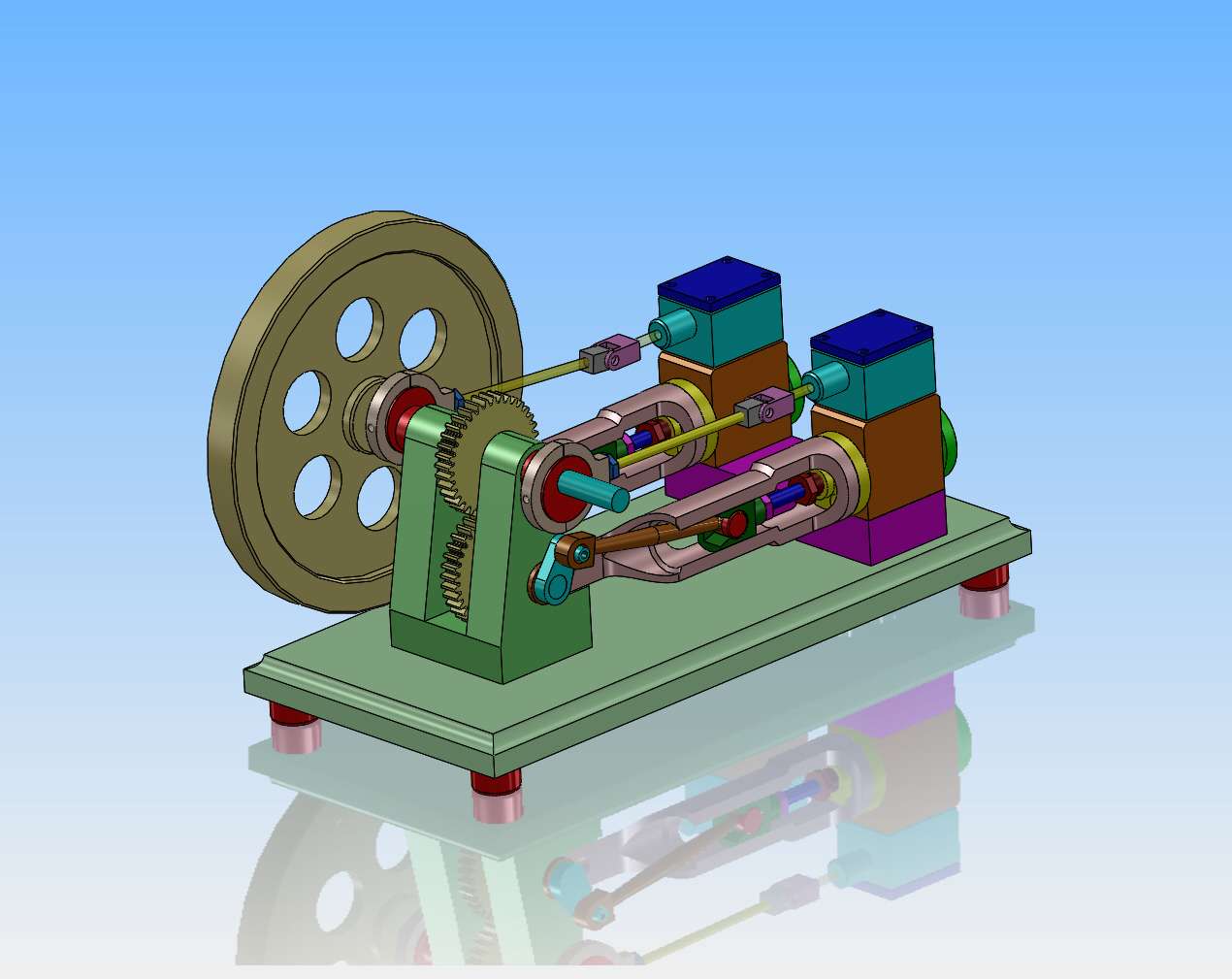
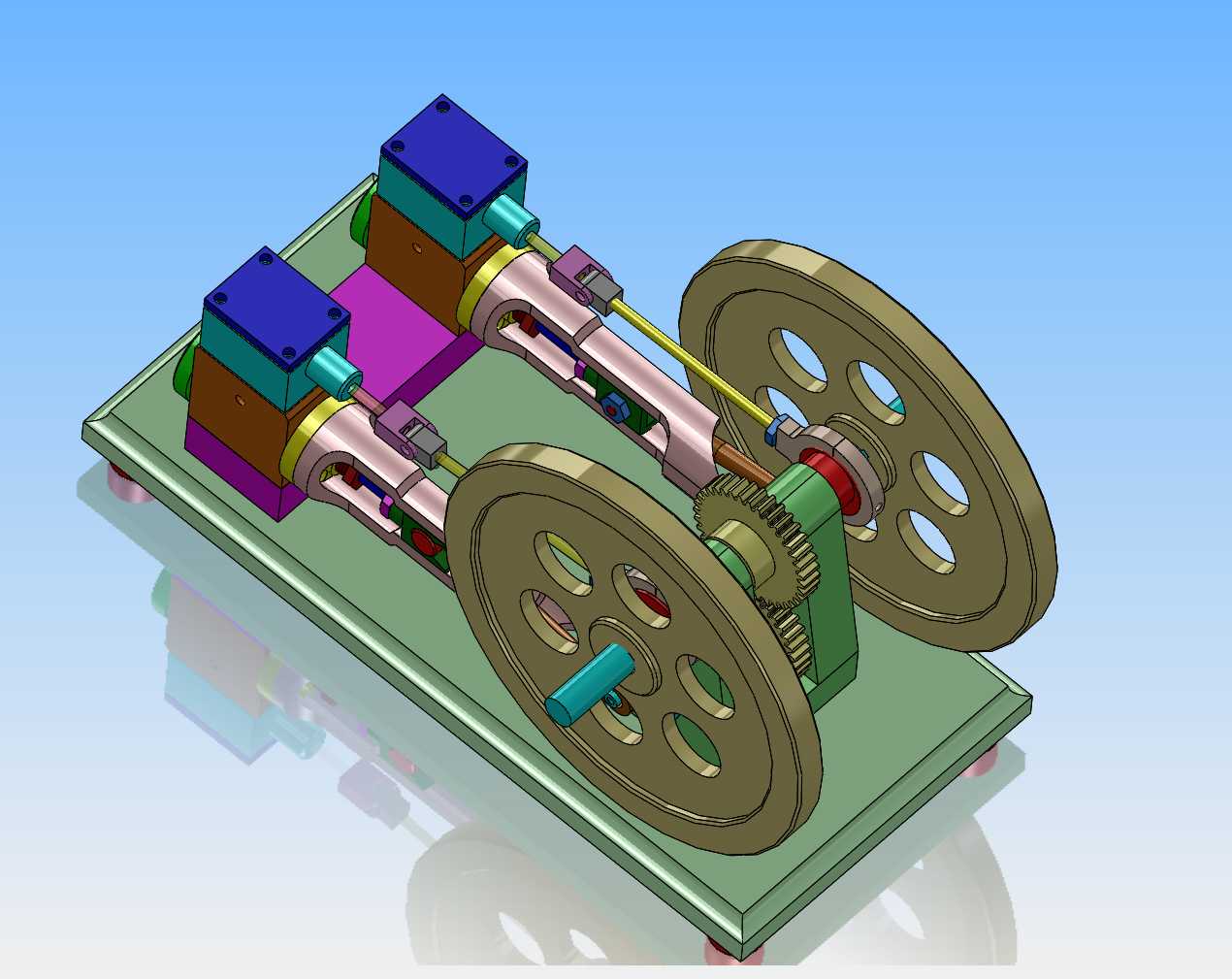
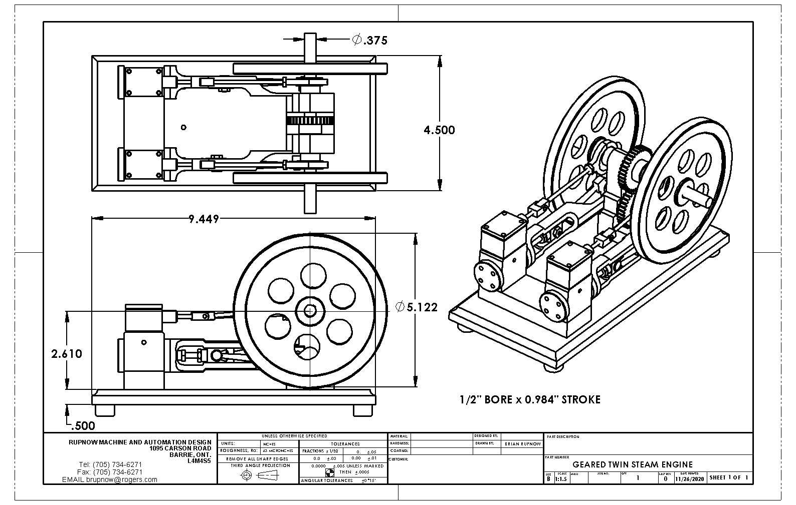
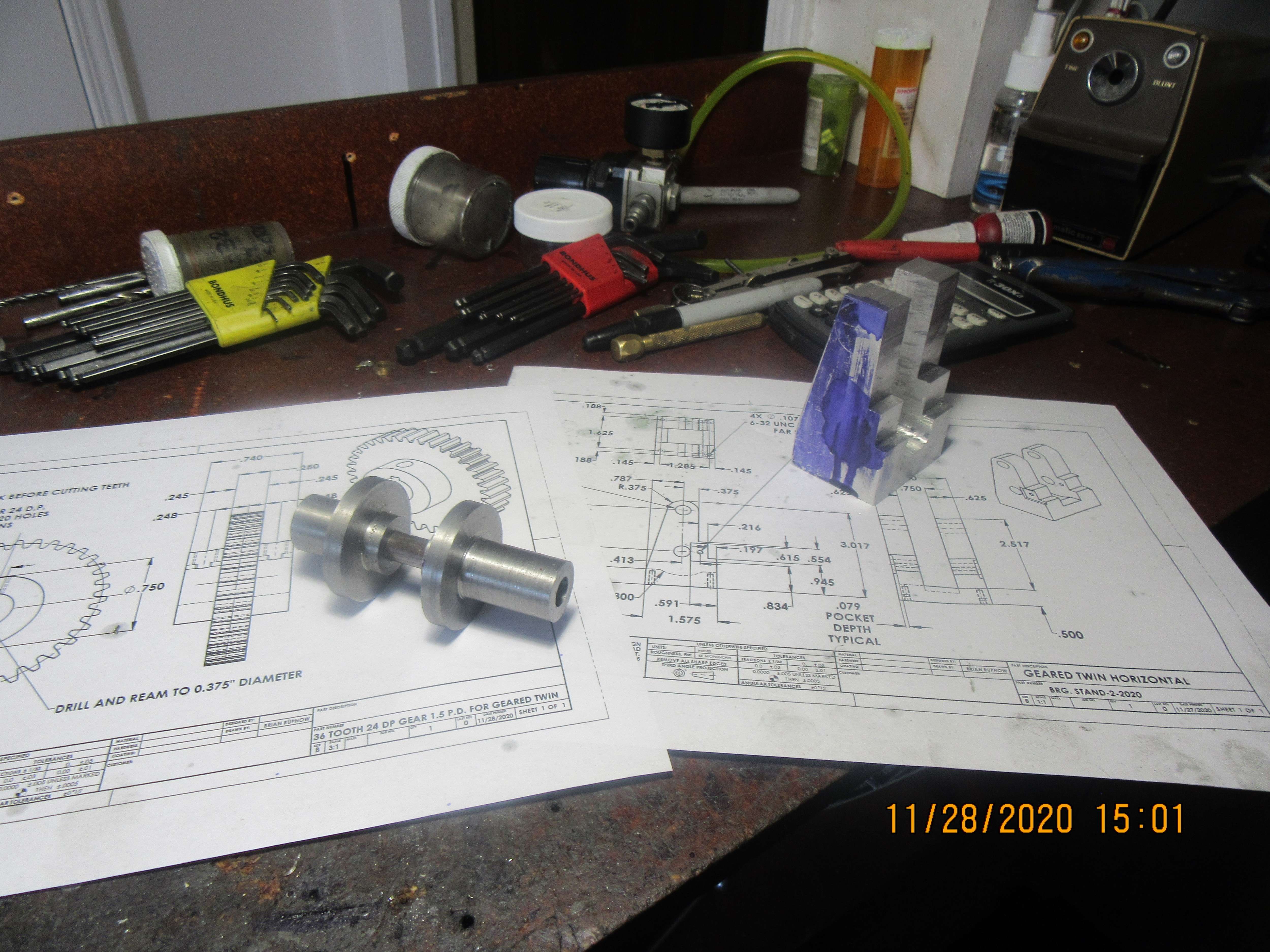
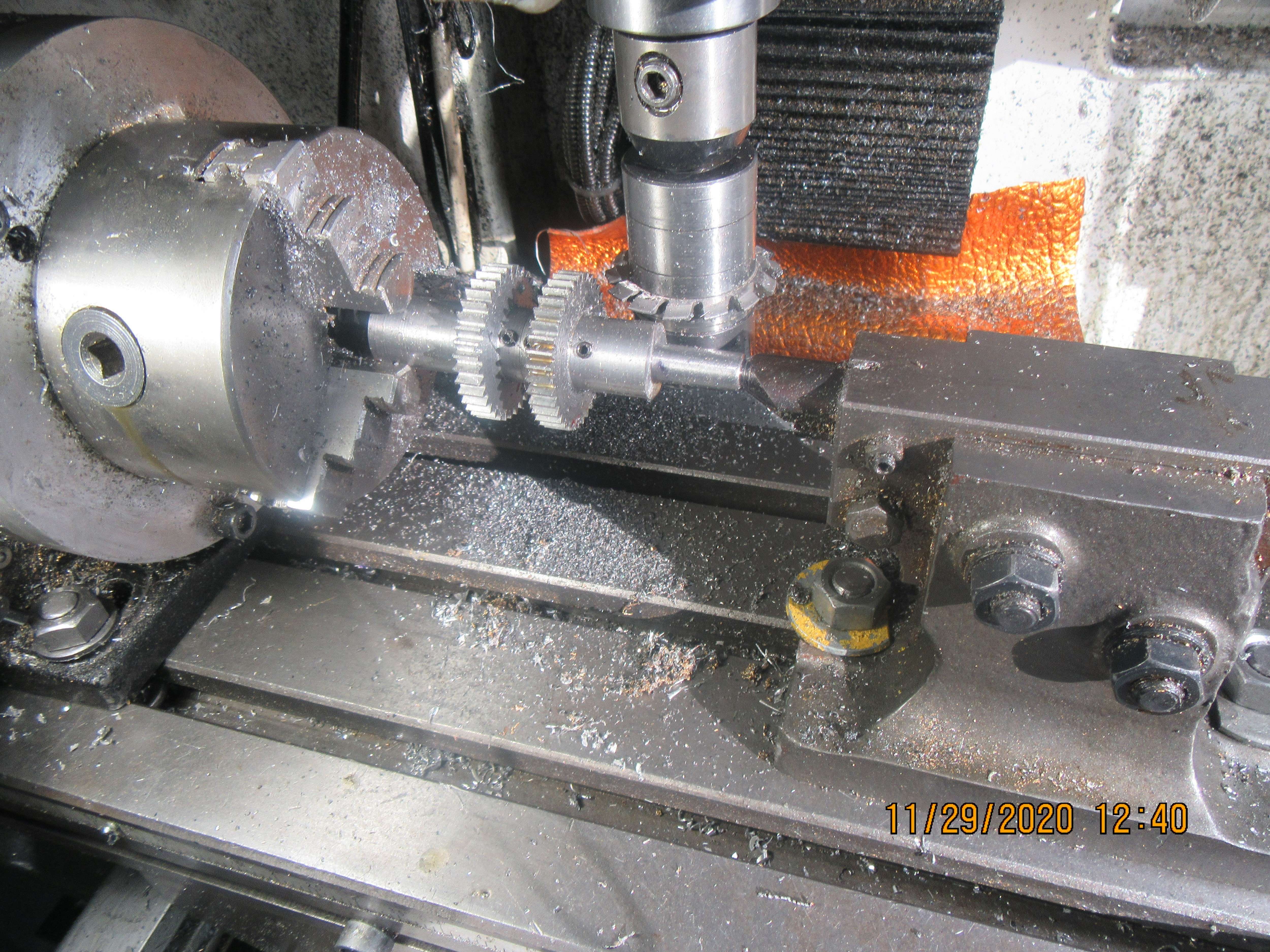
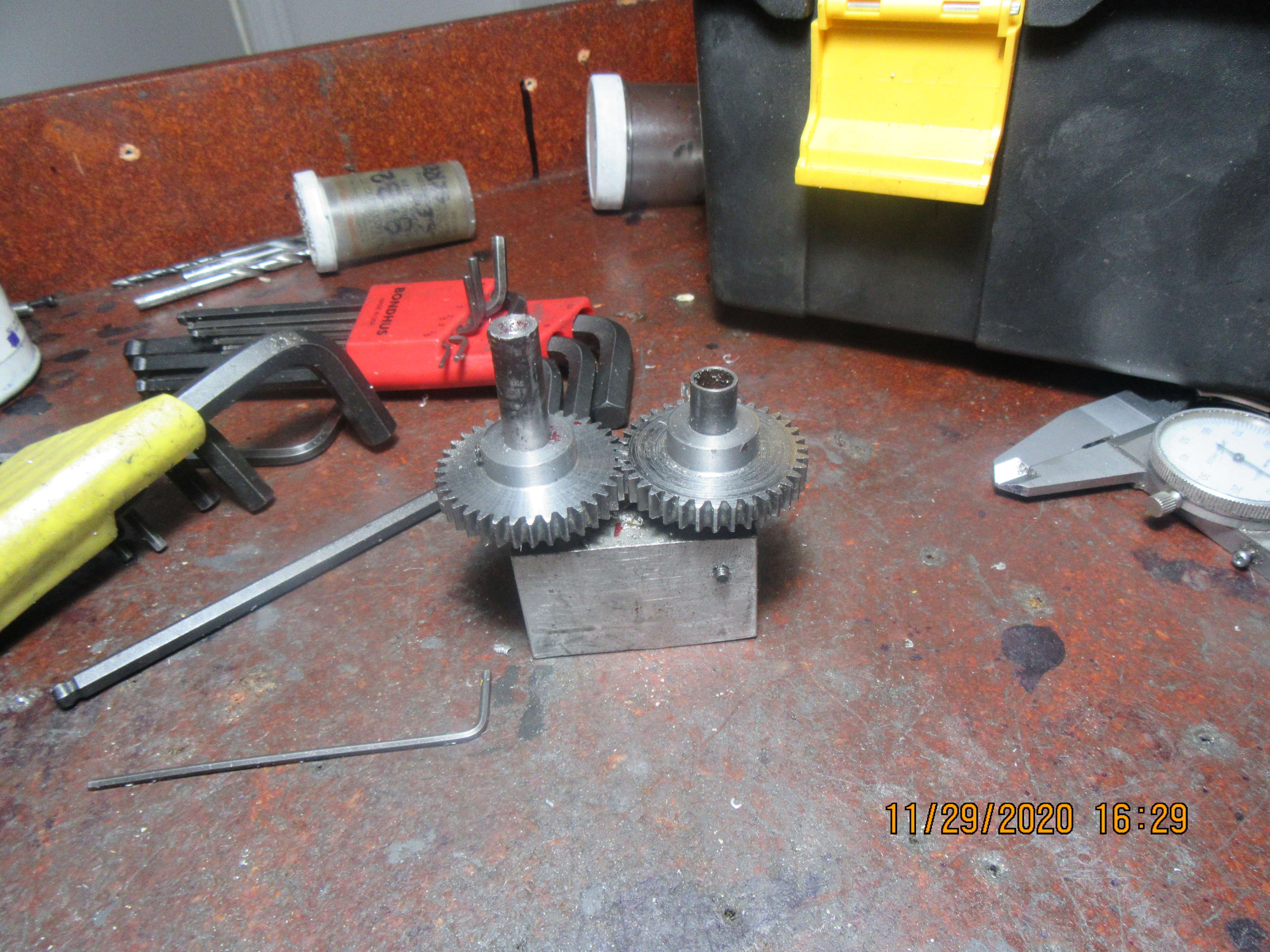
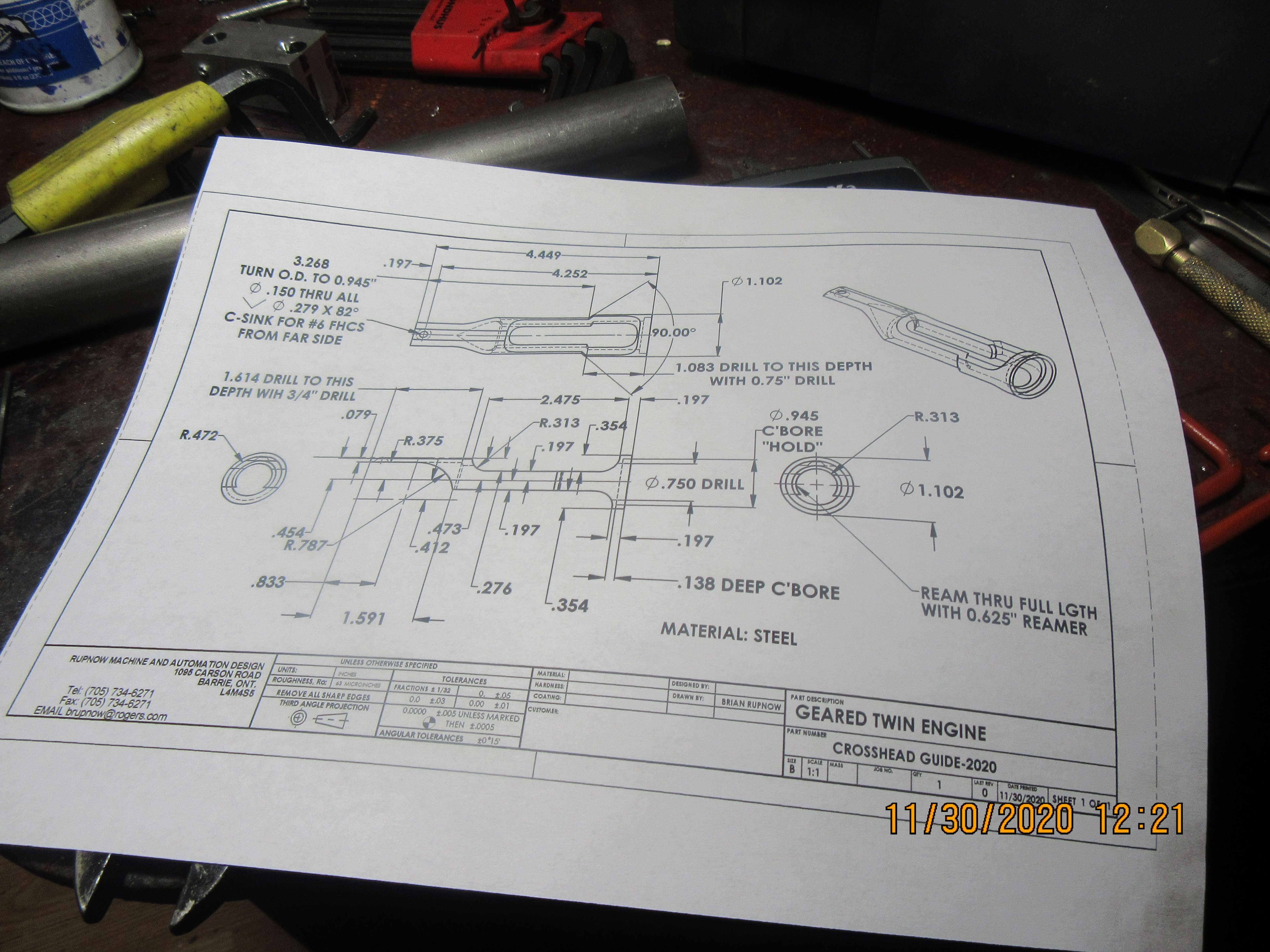
Brian, That's a interesting design, but flywheels on the eccentric shaft and not the crankshaft that intrigues me, could it effect the smooth running of the engine ?
I'll be watching with great interest.
Mike1
Usual practice is to have flywheels on crankshafts - because they are the most substantial for hanging a massive flywheel upon. The largest (stiffest) shaft will have bearings most able to cope with the non-running condition, where all the mass of the flywheel is pressing (usually) on only 1 or 2 bearings. But if another shaft is used, then it often needs to be beefed-up to take a flywheel. Also, the fastest shaft is better for flywheels, as they can be made smaller if running faster. Valve layshafts in whatever form may be running at half crank speed and therefore balance of crank and con-rods is a different set of calculations... - and I think (can't remember - but someone will) you cannot resolve the primary balance with a half-speed shaft. But if the eccentric shaft is separate form the crank and is at crank speed (lie Brian's design), then you may be able to balance the main crank primary mass, providing the linkage between the 2 shafts can cope with the torsional vibration forces.... (=BIG Gears!). So it isn't common practice for many reasons.
With the loads on a model - Like Brian's design - I reckon the gears - if nicely meshed - will do fine. They look big.
Personally, I would have arranged the cylinder above the valve chest - so pistons drive a crankshaft with the flywheels directly mounted, and the eccentrics on the layshaft (below) can then drive the valves directly. Or if the eccentrics remained on the crank (as many engines exist) a simple and light lever could transmit the motion to the valve rods. - But that would be a different design to Brian's.
With Brian's arangement, I think the balancing can be arranged so the primary crank imbalance can be resolved by counterweights on the crankshaft, then some secondary (or are they tertiary?) imbalances from side oscillations of con-rods be compensated by balance weights on the eccentric shaft. How about it Brian?
Can you post your balance configuration and calcs? I'm sure I'm not the only one who wants to learn more about this interesting design. Keep up the good work. - Will plans be available (prints/pdf will do?) when completed, so we can make something unique to display at our local club shows?
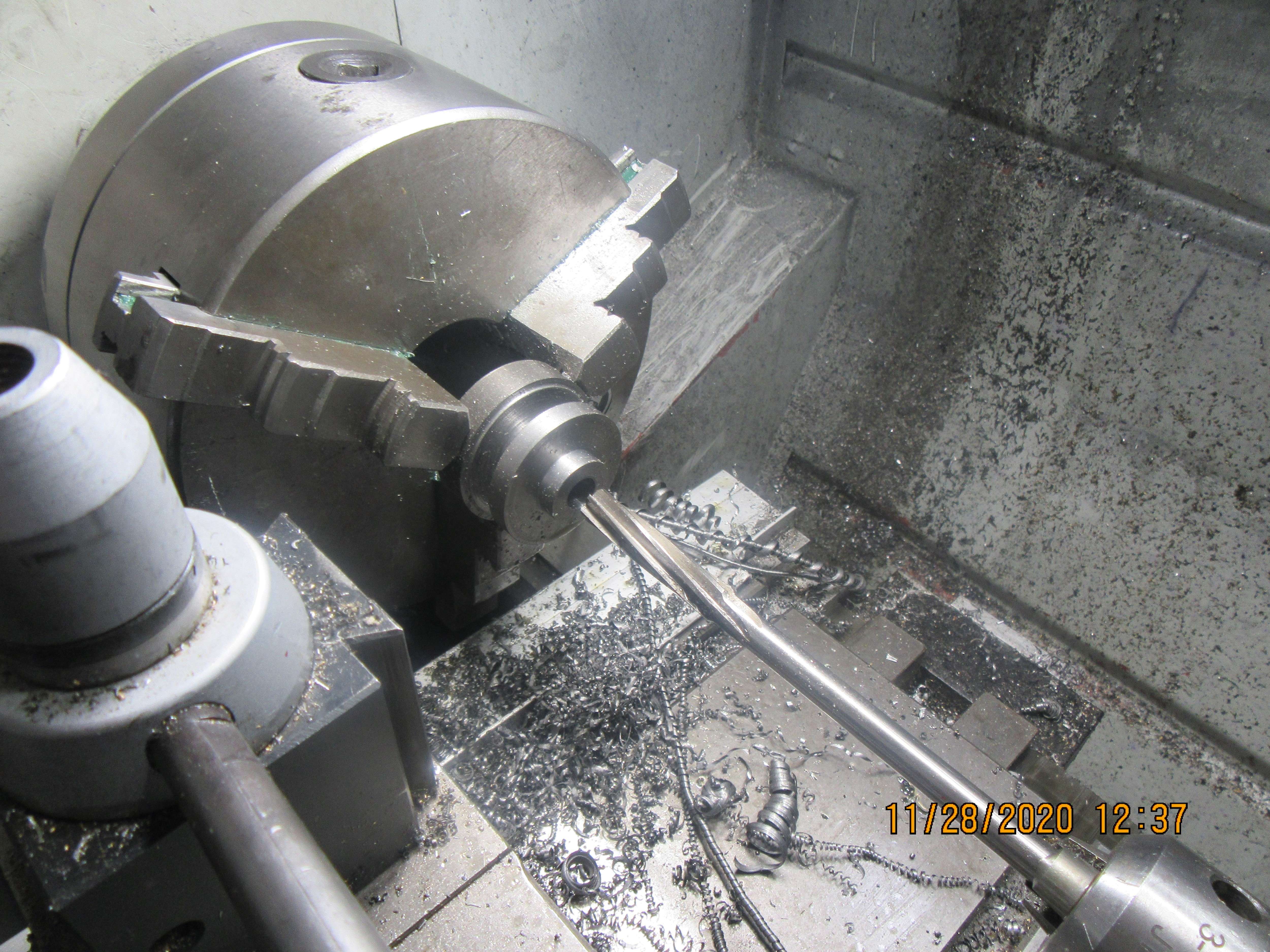
Sorry if my posts are a bit long winded. "new" configurations of engines - like Brian has drawn - really interest me from a design perspective. I can't see any new Machining challenges here?
Thanks Brian.
K2
