You can not harden cold rolled steel unless you use Casenite and surface harden it. Heating it to destress it is just wasted heat.
You are using an out of date browser. It may not display this or other websites correctly.
You should upgrade or use an alternative browser.
You should upgrade or use an alternative browser.
Geared horizontal twin engine
- Thread starter Brian Rupnow
- Start date

Help Support Home Model Engine Machinist Forum:
This site may earn a commission from merchant affiliate
links, including eBay, Amazon, and others.
Todays work consisted of putting oil holes and galleries into the main crankshaft support block, and making all of the crankshaft parts and silver soldering them together. Highlight of the day was a visit from my friend Terry, a gentleman who shares a common interest with myself about building and machining small engines. We both sat around my office wearing masks and telling each other how tired we are of this damned virus thing. Terry has built a few of my engines, and does marvelous work.
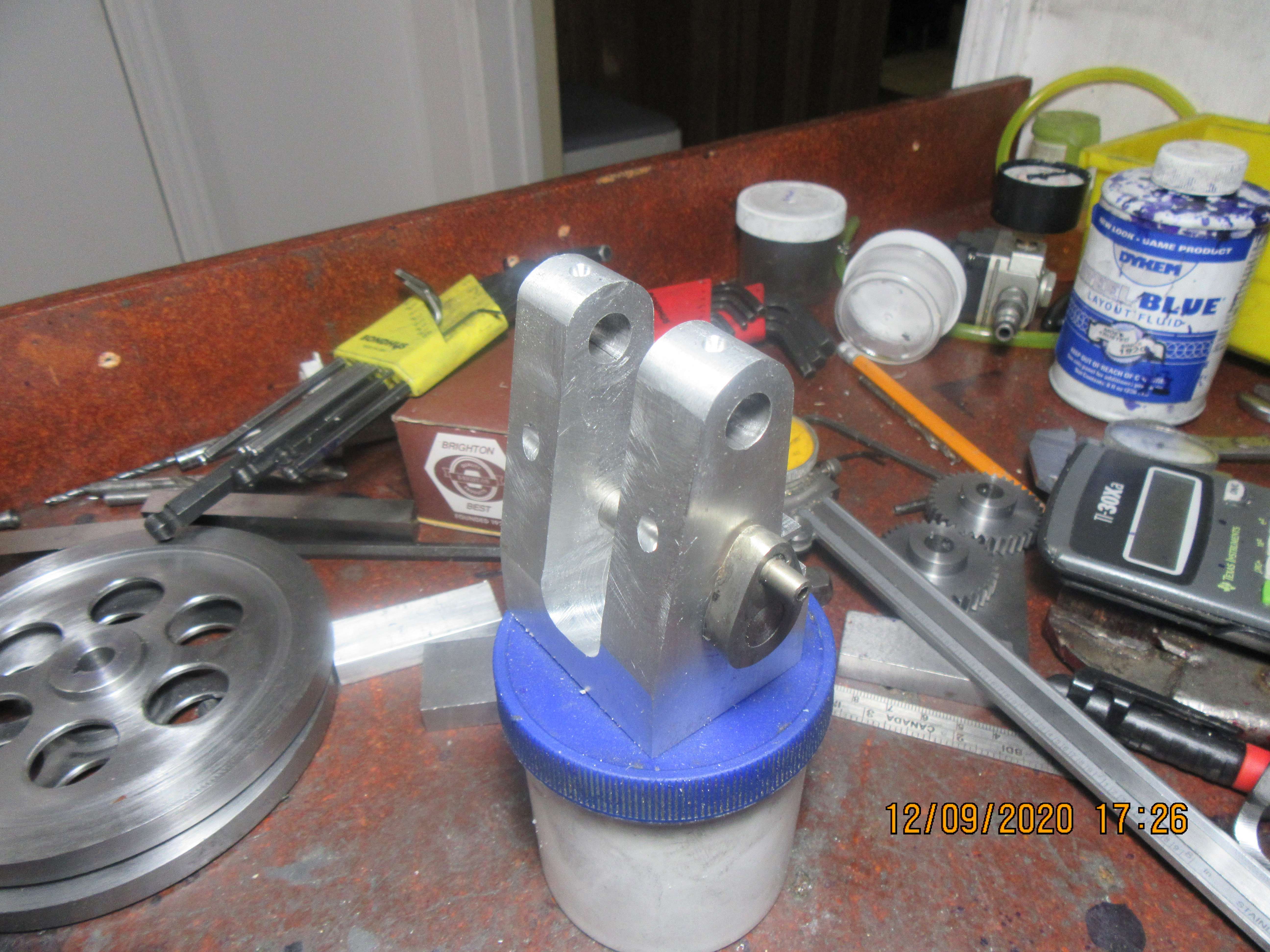

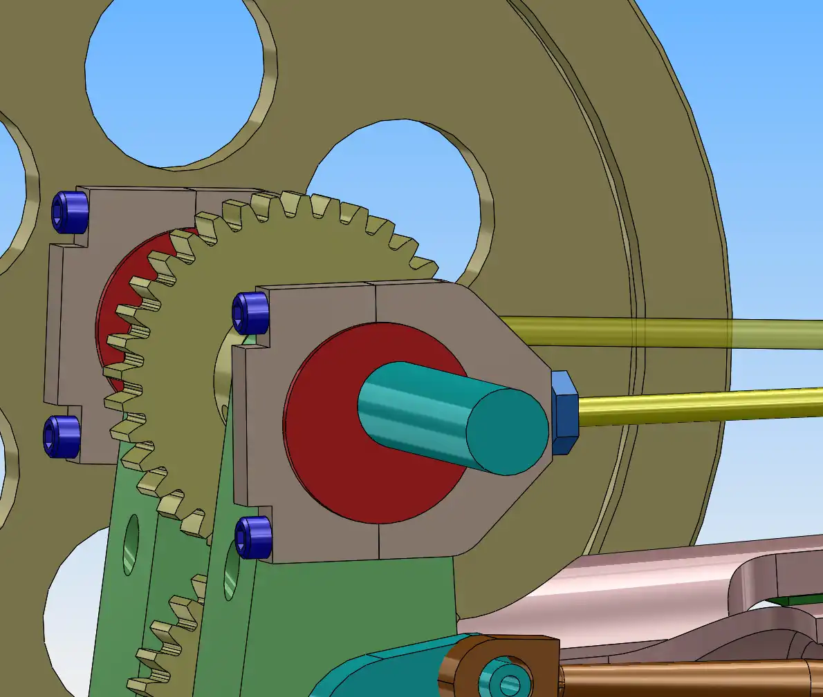
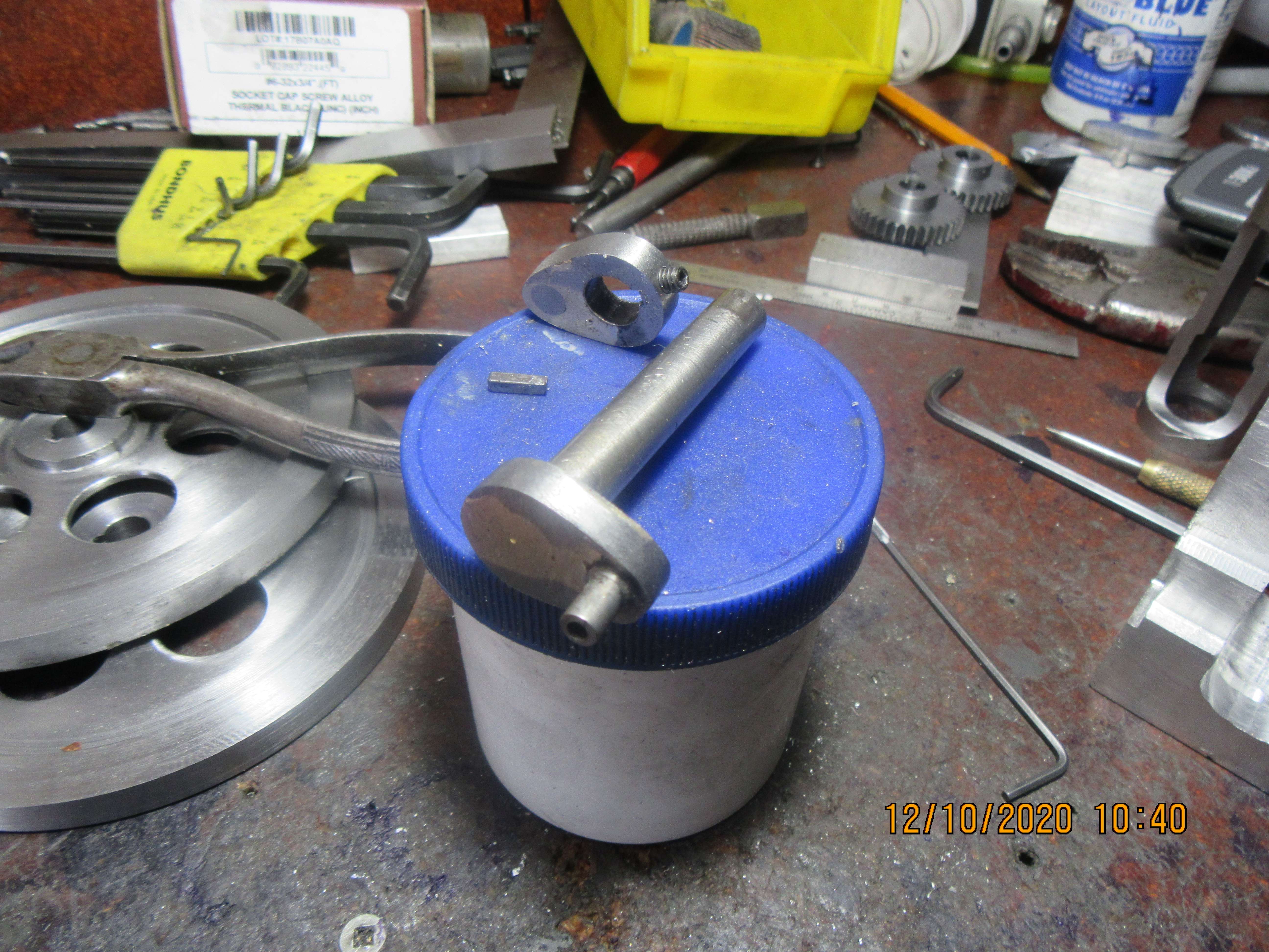
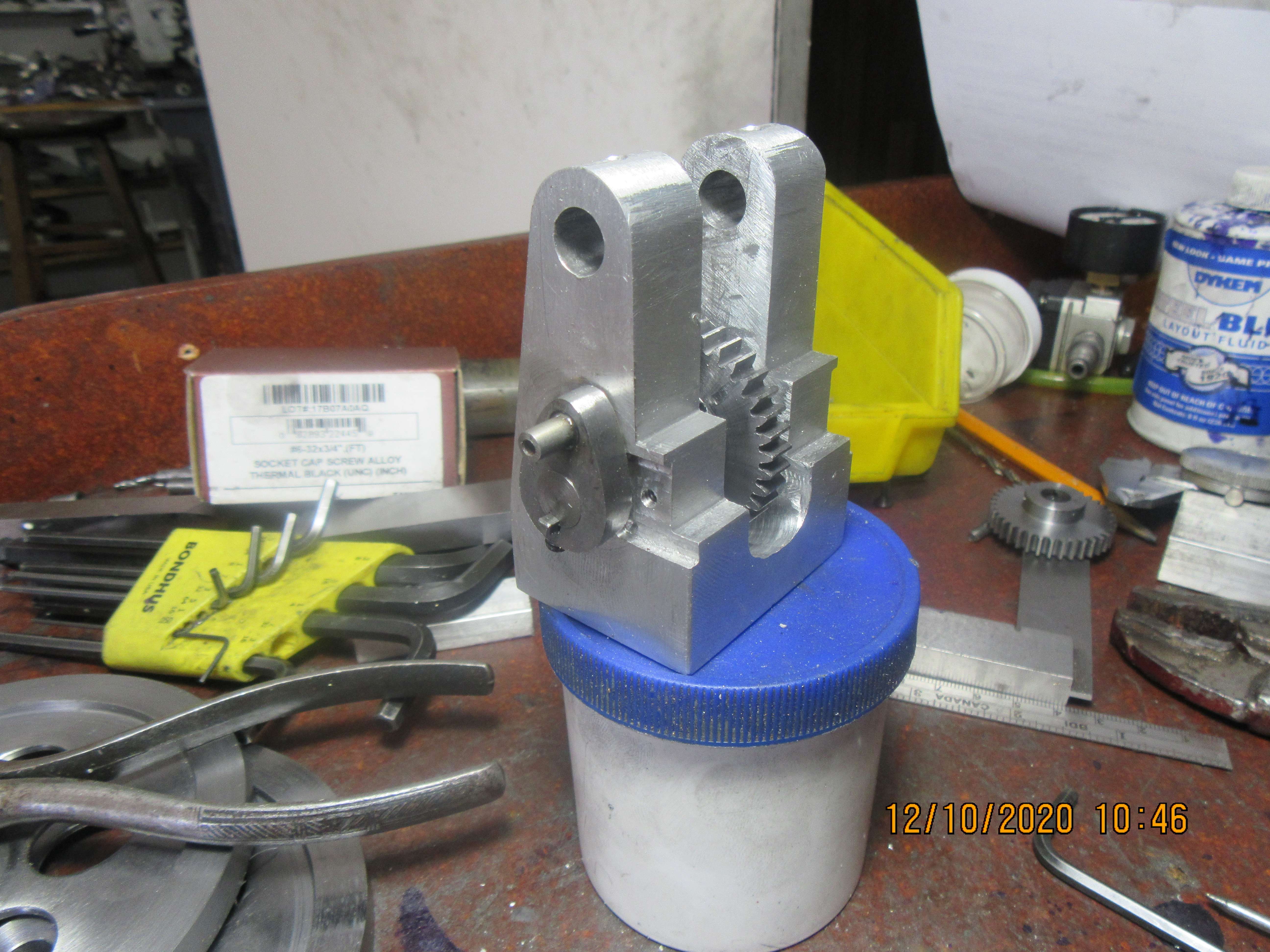
Tomorrow, after I completely finish the crankshaft, I will work on the eccentrics and eccentric straps. In the past I have made one piece eccentric straps and a two piece eccentric to hold the straps in place. That works, but it requires rework to a standard socket head cap-screw to make everything fit into a small area. I'm going to do something a little different here. I will make the eccentric from one piece with a flange on each side to keep the eccentric strap in place. The eccentric strap will be two piece with #4 capscrews holding the two halves together. With this design I can use a standard #4 shcs with no modification, and the eccentric strap ends up being much simpler to machine.

Yes you can stress relieve CRS but doing it before you do the machining would be the way, the reason it warps when being machined is because of the built in stresses from the cold working processes. Because it's stress relieved instead of annealed, if you can do that, it will still machine like CRS instead of HRS, at least that's my experience.Is it possible or a good idea to machine cold rolled to within a few thou, then heat it to destress the stuff and finish later? What about if it is necessary to re-harden it later?
ajoeiam
Well-Known Member
- Joined
- Aug 14, 2020
- Messages
- 1,040
- Reaction score
- 307
If you choose to do such - - - please don't machine to within a 'few thou' - - - - that won't leave you with enough to remove to give you 'good' parts.Is it possible or a good idea to machine cold rolled to within a few thou, then heat it to destress the stuff and finish later? What about if it is necessary to re-harden it later?
I would suggest somewhere between 30 and 50 thou and even then I would be using 2 cuts - - - -you know - - - just in case. (Murphy tends to be a regular visitor when I'm around - - - - grin!)
Crankshaft is finished and installed. No real drama. I have to file off that little bit of key sticking out past the end of the crankshaft, and then I can move on to eccentrics.


![DreamPlan Home Design and Landscaping Software Free for Windows [PC Download]](https://m.media-amazon.com/images/I/51kvZH2dVLL._SL500_.jpg)
$0.00
DreamPlan Home Design and Landscaping Software Free for Windows [PC Download]
Amazon.com Services LLC

$649.00
$699.00
FoxAlien Masuter Pro CNC Router Machine, Upgraded 3-Axis Engraving All-Metal Milling Machine for Wood Acrylic MDF Nylon Carving Cutting
FoxAlien Official

$38.70
$49.99
Becker CAD 12 3D - professional CAD software for 2D + 3D design and modelling - for 3 PCs - 100% compatible with AutoCAD
momox Shop

$99.99
AHS Outdoor Wood Boiler Yearly Maintenance Kit with Water Treatment - ProTech 300 & Test Kit
Alternative Heating & Supplies

$45.99
Sunnytech Mini Hot Air Stirling Engine Motor Model Educational Toy Kits Electricity HA001
stirlingtechonline

$199.99
$209.99
LoCo Cookers SureSpark Seafood Boil/Steam Kit with Hands-Free Twist & Drain, 80 Qt.
Spreetail

$89.99
Outdoor Wood Boiler Water Treatment Rust Inhibitor- AmTech 300 & Test Kit
Alternative Heating & Supplies

$24.99
$27.99
HOZLY 5PCS/Lot ISO30 Tool Holder Clamp Flame Proof Rubber Claw CNC Machines Automatic Tool Changer
HOZLY

$24.99
$34.99
Bowl Sander Tool Kit w/Dual Bearing Head & Hardwood Handle | 42PC Wood Sander Set | 2" Hook & Loop Sanding Disc Sandpaper Assortment | 1/4" Mandrel Bowl Sander for Woodturning | Wood Lathe Tools
Peachtree Woodworking Supply Inc

$39.99
$49.99
Sunnytech Low Temperature Stirling Engine Motor Steam Heat Education Model Toy Kit For mechanical skills (LT001)
stirlingtechonline
Making round parts went quite swimmingly--Until I broke off a #10-24 tap. Tried all of my usual tricks to remove it, and none of them worked. Will remake that part tomorrow morning. BAH!!!----HUMBUG!!!
As an aside, I find that I break more 10-24 taps than any other size. I asked about it on PM one time, and the consensus was that this size requires more torque per cross section than any other, due to the relatively coarse threads. 10-32 is so much easier to tap, so I've tried to switch over to that ... but I have a ton of 10-24 fasteners on hand, so it is hard to leave it behind entirely. Of course, one can always drill a bit larger to get only 50% thread engagement, and that will help considerably ... but too often I forget that little trick until just after I hear the "tink" of the tap breaking. Grrr ...
Richard Hed
Well-Known Member
- Joined
- Nov 23, 2018
- Messages
- 2,759
- Reaction score
- 736
Yes, oversized holes help a lot but I also found that 3-flute taps are stronger than 4 flutes. I never buy 4 flutes. I thimk that odd flutes are better than even, howeveer, I am not too sure about that. I just notice that three flutes are better ones (in mhy not very humble opinion) than four. Anybody else notice this?As an aside, I find that I break more 10-24 taps than any other size. I asked about it on PM one time, and the consensus was that this size requires more torque per cross section than any other, due to the relatively coarse threads. 10-32 is so much easier to tap, so I've tried to switch over to that ... but I have a ton of 10-24 fasteners on hand, so it is hard to leave it behind entirely. Of course, one can always drill a bit larger to get only 50% thread engagement, and that will help considerably ... but too often I forget that little trick until just after I hear the "tink" of the tap breaking. Grrr ...
I've switched to using spiral point or spiral flute taps - the former is two-flute in the 10-24 size, and pushes chips ahead of itself (perfect for through holes); I'm not sure how many flutes the latter is - may only be two flutes - this type pulls the chips out. Both of these have improved my success rate ... but still the 10-24 size is the easiest to break, at least of the taps I regularly use.
Richard Hed
Well-Known Member
- Joined
- Nov 23, 2018
- Messages
- 2,759
- Reaction score
- 736
come to thimk of it, I believe 2 flutes are far better than four. For some reason, four flutes are weak in the middle where they are connected to the center.I've switched to using spiral point or spiral flute taps - the former is two-flute in the 10-24 size, and pushes chips ahead of itself (perfect for through holes); I'm not sure how many flutes the latter is - may only be two flutes - this type pulls the chips out. Both of these have improved my success rate ... but still the 10-24 size is the easiest to break, at least of the taps I regularly use.
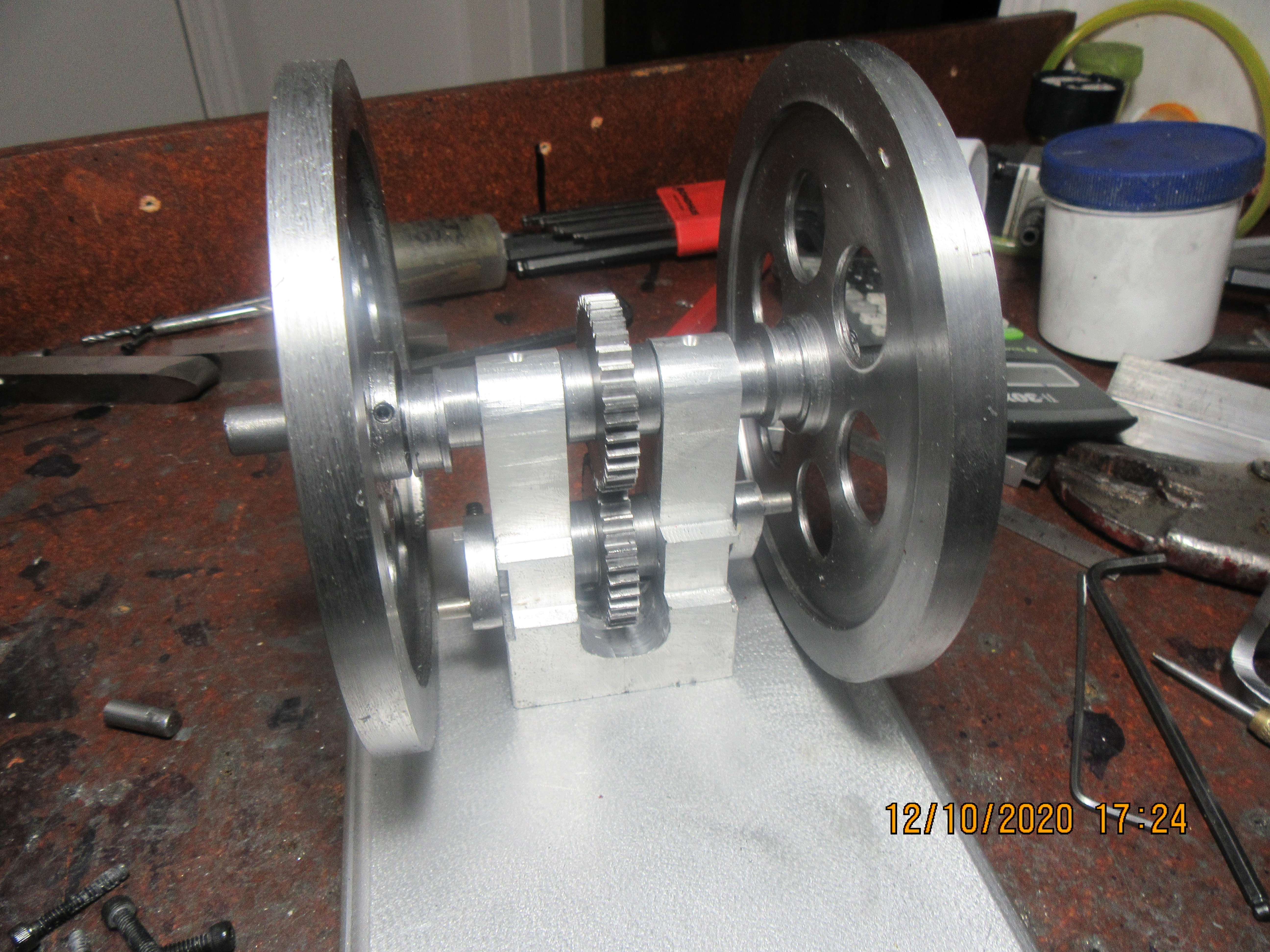
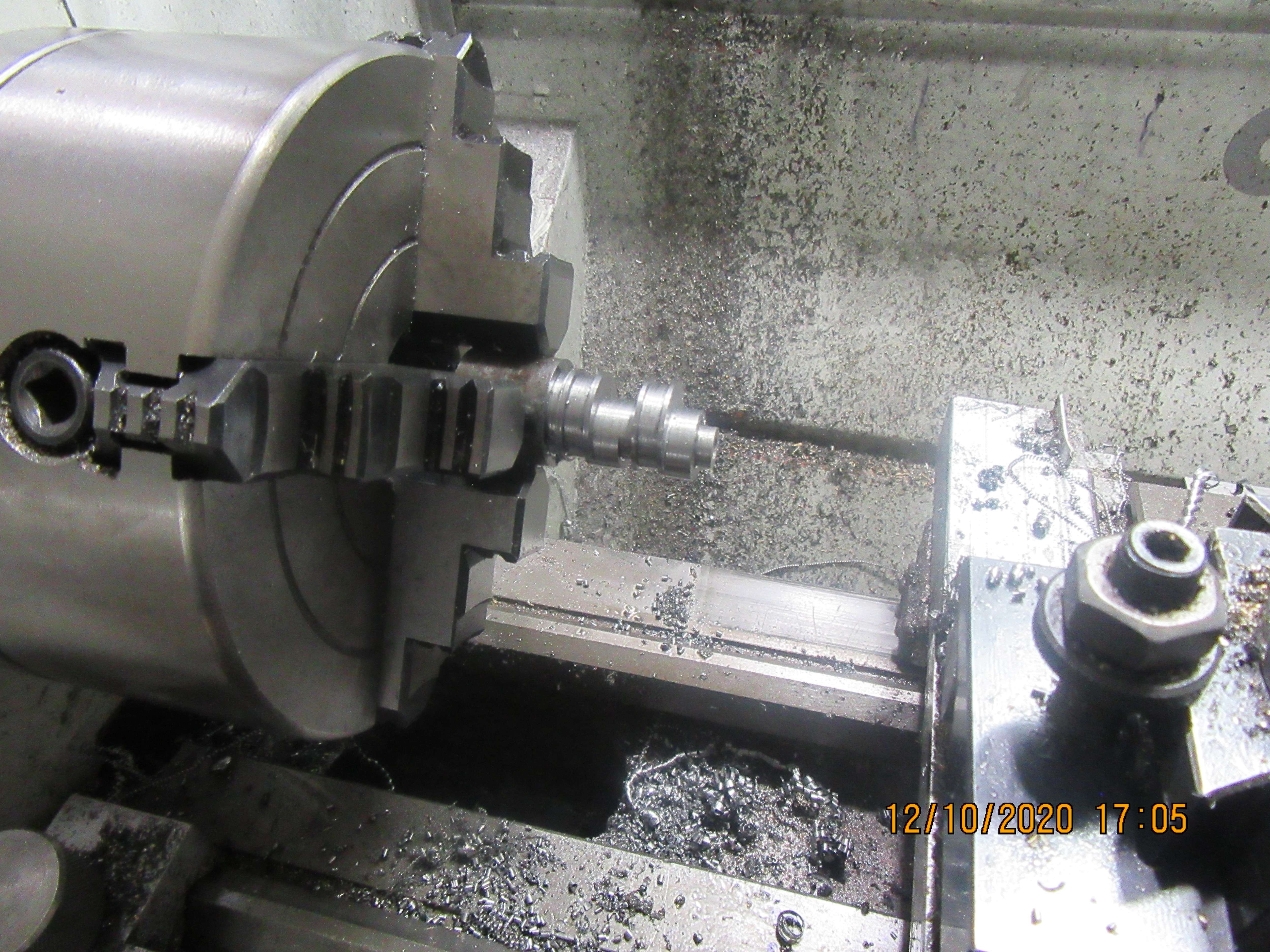
Every time I make eccentrics, I seem to find a slightly different way of machining them. These turned out quite well, and all I have to do now is drill and tap them for set screws. They do not get a keyway, as they have to be able to rotate on the shaft to set the timing.


Tim Wescott
Well-Known Member
- Joined
- Jun 3, 2018
- Messages
- 328
- Reaction score
- 99
So, your method of machining eccentrics is always -- eccentric?
Tim--My wife said the same thing. She said she was going to bring her camera down to my shop and take a picture of "An eccentric machining an eccentric" and paste it on Facebook!!!
Richard Hed
Well-Known Member
- Joined
- Nov 23, 2018
- Messages
- 2,759
- Reaction score
- 736
That's a real insult alright! Who, in their right mind, would use facecrook?Tim--My wife said the same thing. She said she was going to bring her camera down to my shop and take a picture of "An eccentric machining an eccentric" and paste it on Facebook!!!
My wife is a political hack. She worked most of her life for the federal government in Canada, and loved every minute of it. Now she gets on facebook and fights with all the Americans about their own political shenanigans. I keep telling her to leave the Americans alone, or we'll be having the black helicopters landing in out back yard.
Richard Hed
Well-Known Member
- Joined
- Nov 23, 2018
- Messages
- 2,759
- Reaction score
- 736
I understand--it's a real comedy. If the black helis showed up at my place, I'd just tell them, "Here I am, where's the handcuffs?" The onlyway to stop those criminals is to jam the prisons with innocent victims--they can't afford to put us all in prisons or FEMA concentration camps. Too costly.My wife is a political hack. She worked most of her life for the federal government in Canada, and loved every minute of it. Now she gets on facebook and fights with all the Americans about their own political shenanigans. I keep telling her to leave the Americans alone, or we'll be having the black helicopters landing in out back yard.
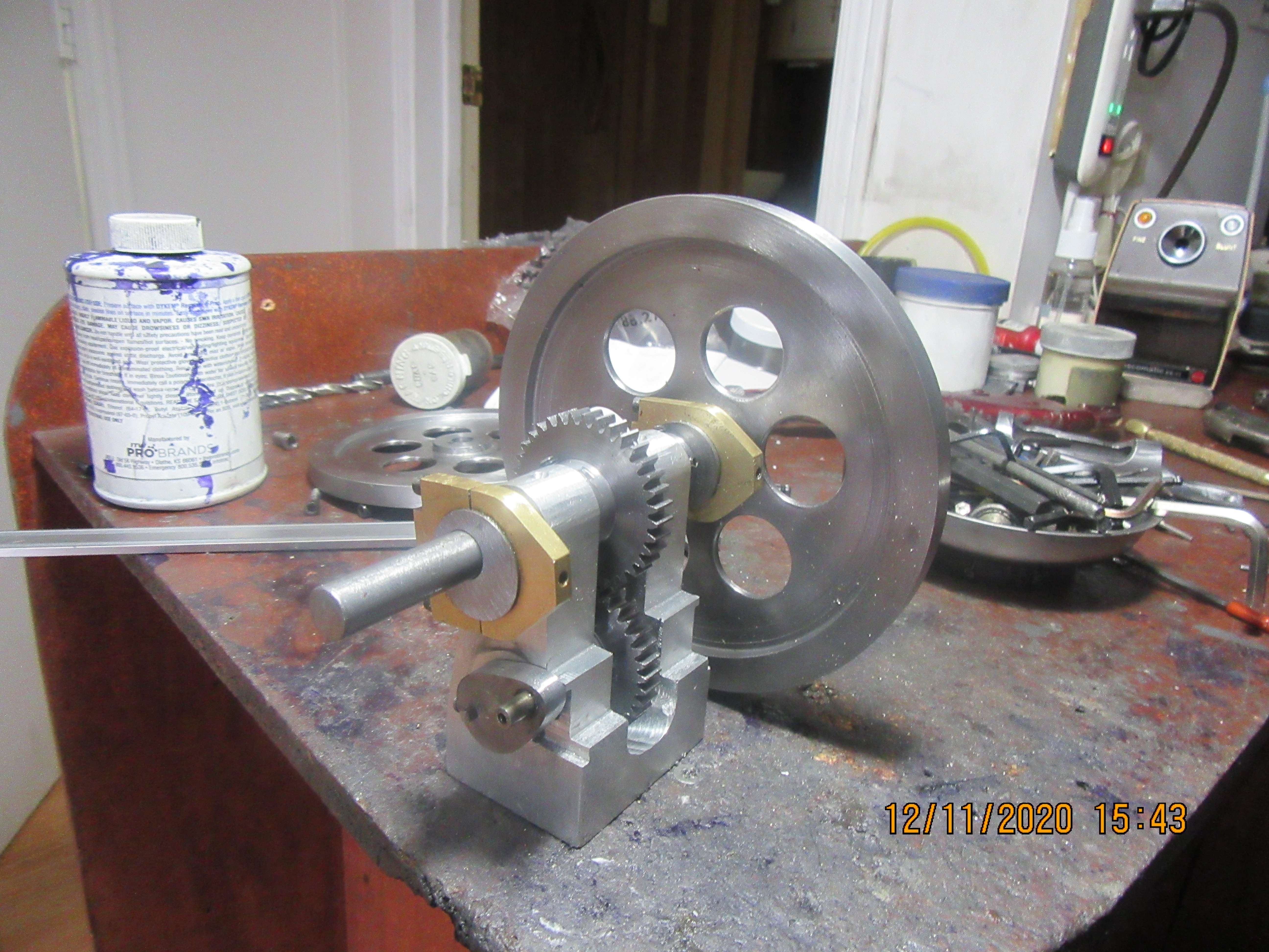
The eccentric straps are finished and installed. The flanges on the eccentrics keep the straps from moving side to side, and yes, they do miss the crankshaft throws when everything is rotated.

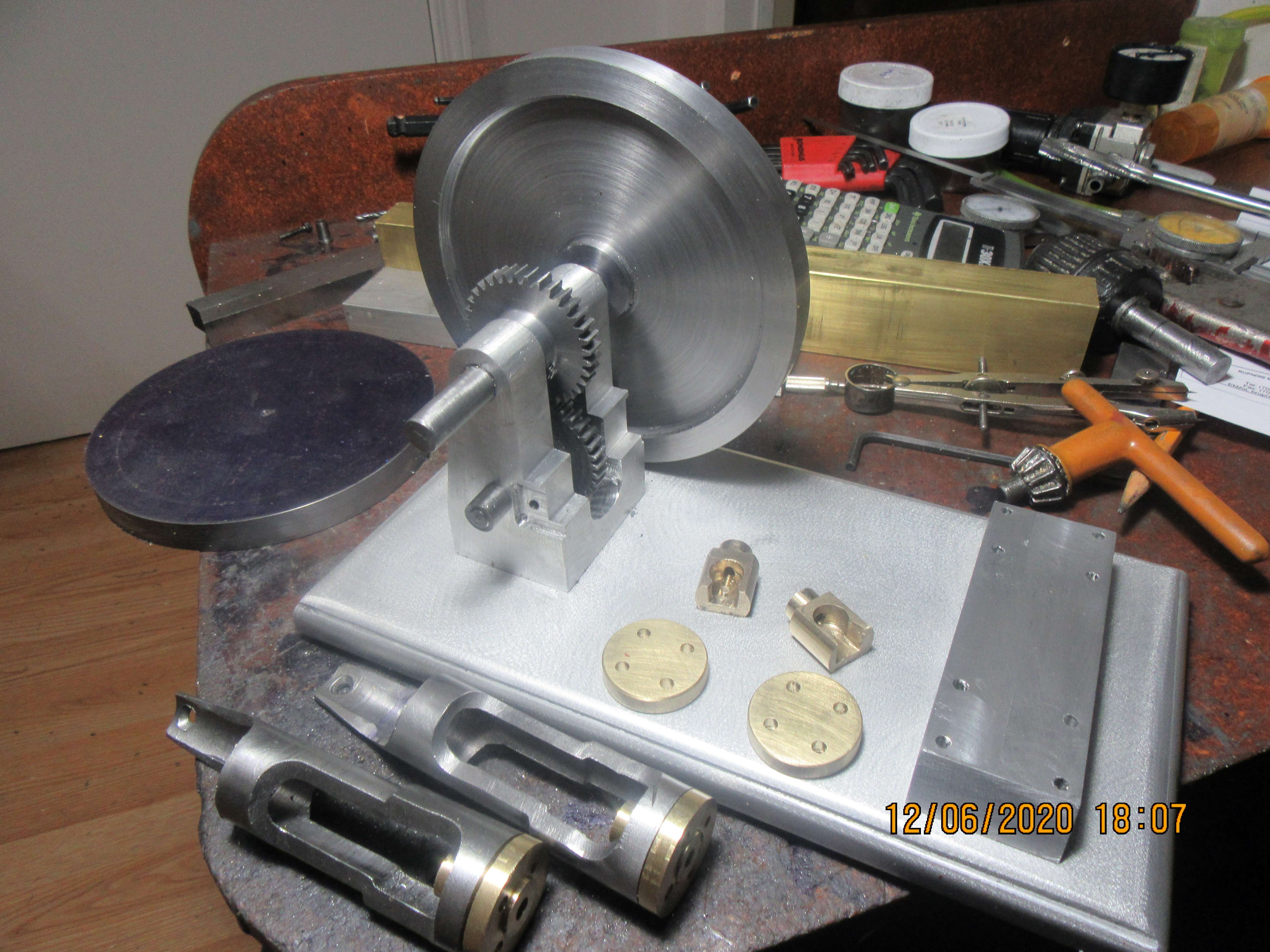
What are the engineering and mathematical considerations in thinning the inner portion of a flywheel, leaving a thick rim?Every day, a few more parts. Hardest job of the day was standing out in my unheated main garage sawing out flywheels from that piece of 6" x 1/2" hot-rolled steel. I need a new blade on the saw, and it doesn't cut very fast right now---and if you lean on it a bit then the drive belt slips. ---Thought I might freeze to death before I got the flywheels cut out. Tomorrow I hope to completely finish the flywheels.
I understand the mass at the greater radius absorbs, or delivers, more torque than mass closer to the center of rotation.
In commercial installations of colossal size and weight, such as the Tod Engine in the Youngstown, Ohio steel rolling plant , reducing the less "productive" mass near the axle eases the bearing load, but at what loss to the energy storage of the system?
In model engines appearance counts as much as function, and barbell weights win no prizes.
Sorry to send you back to your freshman Mechanics texts, but if you have any questions on Photographic Engineering, perhaps I can be of help.
Thanks,
Larry
It is really only the outer rim of the flywheel on an engine that does the work. If you could build a flywheel with a hub area for mounting it on the shaft, and the last 1/2" of the outer rim, you wouldn't even really need the thinned out web section. Of course that's not really possible, so you thin down the web area as much as you can, because the mass in the web area isn't really doing anything to help the engine run. A double acting steam engine is always under power, going either direction---except---at top dead center and at bottom dead center where there is a "dead spot". The inertia of the flywheel rotates the engine thru these momentary "dead spots". On a single acting steam engine or on a 2 cycle engine, the flywheel inertia keeps the crankshaft turning thru 180 degrees of the complete circle where the engine is not "under power". On a 4 cycle i.c. engine, it gets even worse, the flywheel has to actually rotate the crankshaft thru a full 360 degrees before another "power stroke". Hope that answers your question, without going into the physics of flywheel design.---Brian
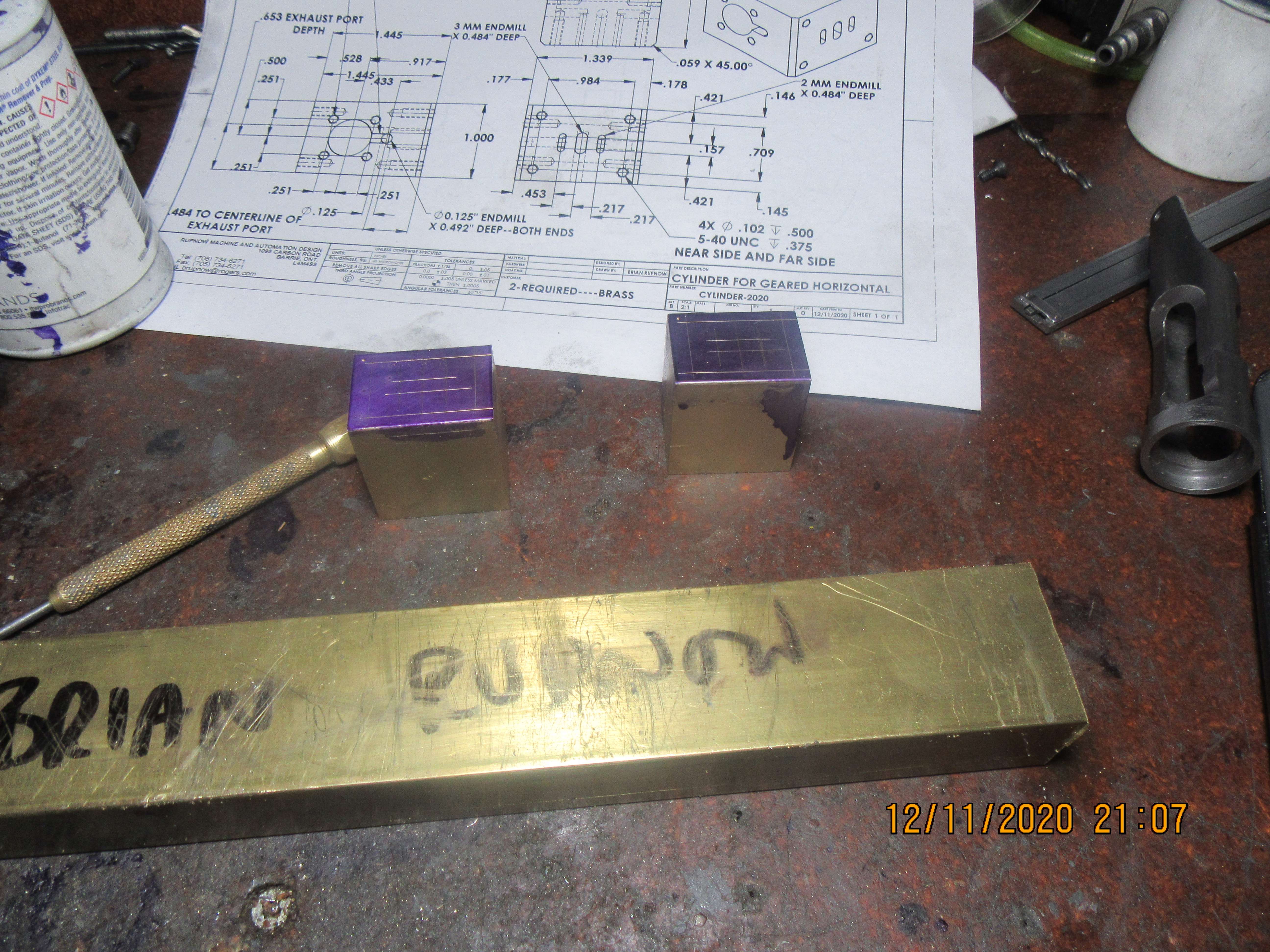
Tomorrow I start making cylinders. These cylinders are a bit different, because there is no profiling on the outside. They are rectangular, but there is a lot going on inside. I have made the tapped mounting holes in the underside in exactly the same position as the tapped mounting holes in the topside where the steam-chest bolts on. Two ends are tapped for cylinder end-caps, and two remaining sides are blank. (Except for the exhaust exit hole).

Similar threads
- Replies
- 510
- Views
- 73K
- Replies
- 413
- Views
- 64K
- Replies
- 27
- Views
- 7K
- Replies
- 148
- Views
- 26K


