Electronic Dividing Head using the Arduino

Home Model Engine Machinist Forum

Help Support Home Model Engine Machinist Forum:

This site may earn a commission from merchant affiliate links, including eBay, Amazon, and others.
Here is a link to yet another version of an Arduino based index head

I have a little different "user interface" - the way of entering the steps, degrees and such. I'd like to hear/see how yours performs under the mill... I'm haven't fully tested mine yet and am wondering if the steppers will give the needed accuracy for (light duty) gear cutting.

=Alan R.

Nice work Alan. I had wanted to use a rotary encoder on my project but thats too much learning for my first attempt... the addition of divisions and jog functions is great... will you post some arduino code so people can learn more from your project?

John
 
The user interface using a rotary encoder and 8 segment display units is pretty slick. I've thought about using a rotary encoder with included push button switch for setting values and selecting menu options.

I would point out, however, that the electronic circuitry and Arduino programming required for this model is considerably more complex than is required for a simple Arduino dividing head. I mention this only because I would hate to see folks pass up a very useful and fun project thinking it's beyond their capability.

This is the circuit I originally built...

ArduinoDividingHead_zps5079d80a.png


And the sketch (Arduino Program) is attached below. This is about as simple as you can get and still have pretty good functionality. The program could be changed to include degree functions or other changes. It's also a good platform for learning more about how to program the Arduino.

By the way, module to the left is a Sainsmart LCD keypad module (shield) that plugs in on top of an Arduino UNO

Chuck

View attachment dividing_head.zip
 
Last edited:
TorontoBuilder;

Thank you for taking this on. I'm eagerly awaiting the finished project. I too am wondering about the torque rating for the motor.

Ron

I have an update for you. I wanted to design a divider head controller that is as universal as possible and would be pretty much plug and play to allow for different power supplies and stepper motor voltages.

My brother and I also have issues with our hands so I wanted bigger actuator buttons, and I thought lighted buttons would be nice, so I created a "break out board that would allow easy attachment of buttons to any case people wanted to make. This solution also allows greater clearance from the LCD screen, and solves issues with the height differential between the buttons and screen which makes mounting difficult.

I also designed my own Arduino board to allow for the voltage input to best match the stepper motor requirement (any input voltage between 5V-36V is acceptable). There are two voltage regulators drive the other components such as the lighted buttons, the cooling fan, the power indicator and of course the arduino control itself.

Onboard connectors allow for easy plug in attachment of a two or 4 line LCD display, the button break out board, the stepper driver carrier, 5V regulator, power switch and LED power indicator.

Once I have the system tested I'll be making the pcb source code available on OSH Park.com.
 
The user interface using a rotary encoder and 8 segment display units is pretty slick. I've thought about using a rotary encoder with included push button switch for setting values and selecting menu options.

I would point out, however, that the electronic circuitry and Arduino programming required for this model is considerably more complex than is required for a simple Arduino dividing head. I mention this only because I would hate to see folks pass up a very useful and fun project thinking it's beyond their capability.

This is the circuit I originally built...

ArduinoDividingHead_zps5079d80a.png


And the sketch (Arduino Program) is attached below. This is about as simple as you can get and still have pretty good functionality. The program could be changed to include degree functions or other changes. It's also a good platform for learning more about how to program the Arduino.

By the way, module to the left is a Sainsmart LCD keypad module (shield) that plugs in on top of an Arduino UNO

Chuck

My sentiments exactly Chuck... which is why I wanted to take the next step and make it even easier for people to take advantage of your work...
 
In case anyone is interested I've attached my prototype schematics & pcb board layout drawing for an arduino compatible microcontroller optimized to run a stepper motor and sketches such as Chuck Fellows electronic indexing head.

This smaller than normal controller has headers for plug and play 20x4 or 16x2 LCD displays, and an LED lighted 5 button break out board, and the main Arduino ATmega 328PU controller board.

NOTE: try these now at your own risk since I havent yet assembled a test circuit.

Comments are very welcome.

In addition to these boards the controller will require two pololu parts,
1. Pololu 5V, 500mA Step-Down Voltage Regulator D24V5F5
2. A4988 Stepper Motor Driver Carrier, Black Edition

Once I get the schematic verified and tested I'll modify the circuit to include a slightly bigger board option that has jumpers to adapt the system to use any of the following Pololu stepper carrier boards which have slightly different voltage input configurations.

DRV8825 Stepper Motor Driver Carrier, High Current or;
DRV8824 Stepper Motor Driver Carrier, Low Current or;
DRV8834 Low-Voltage Stepper Motor Driver Carrier

Attachments one,
button schematic and break out pcb board
main board schematic and pcb board

divider-head-main-board-schematic.jpg


divider-head-main-board-pcb.jpg


lighted-button-breakout-board-schematic.jpg


lighted-button-breakout-board-pcb.jpg
 
Last edited:
Here is a link to yet another version of an Arduino based index head
Fresh ideas are always nice.
I have a little different "user interface" - the way of entering the steps, degrees and such.
Very nice minimalist interface. The only thing I might suggest is a forward and reverse push button. Of course then you have to deal with backlash.
I'd like to hear/see how yours performs under the mill... I'm haven't fully tested mine yet and am wondering if the steppers will give the needed accuracy for (light duty) gear cutting.


=Alan R.


Accuracy will depend a great deal on the ratio between the motor and the spindle on the indexer. Think of a manual indexer with dual worm gear reduction of other methods to make each "step" fine. In the end your stepper will have 200 full steps to work with or 1.8 degrees per step. Micro stepping might cut that by a fourth reliably. For many gears that will be too course.

As for testing yours, the thing to consider is the ability to withstand or lock against cutting forces and the torque they may introduce. Obviously that depends upon many factors, but in this case you have a light duty indexer. That doesn't mean much as you can use the same electronics to drive a spindle via a worm reduction, use a bigger motor, brake or whatever.
 
The user interface using a rotary encoder and 8 segment display units is pretty slick. I've thought about using a rotary encoder with included push button switch for setting values and selecting menu options.

I would point out, however, that the electronic circuitry and Arduino programming required for this model is considerably more complex than is required for a simple Arduino dividing head. I mention this only because I would hate to see folks pass up a very useful and fun project thinking it's beyond their capability.

This is the circuit I originally built...

ArduinoDividingHead_zps5079d80a.png


And the sketch (Arduino Program) is attached below. This is about as simple as you can get and still have pretty good functionality. The program could be changed to include degree functions or other changes. It's also a good platform for learning more about how to program the Arduino.

By the way, module to the left is a Sainsmart LCD keypad module (shield) that plugs in on top of an Arduino UNO

Chuck

Here's a couple of photos of my version. One mod I would make to mine, is to reduce the distance from the stepper to the spindle. Other than that, it's nearly the same. I used a 400 step motor, and a 4:1 ratio of the pulleys... As Chuck mentions, this really was a simple build...er, well at least where the electronics were concerned. In my case, the machine work was the challenge! ;)

uP_div_hd2.jpg


uP_div_hd1.jpg
 
In case anyone is interested I've attached my prototype schematics and pcb board layout drawing for the lLED lighted button break out board, and the main Arduino ATmega 328PU controller board.

NOTE: try these now at your own risk since I havent yet checked the values for the switching regulator & inductor circuit or yet assembled a test circuit in a breadboard for a test.

Comments are very welcome.

In addition to these boards the controller will require two pololu parts,
1. Pololu 5V, 500mA Step-Down Voltage Regulator D24V5F5
2. A4988 Stepper Motor Driver Carrier, Black Edition

Once I get the schematic verified and tested I'll modify the circuit to include a slightly bigger board option that has jumpers to adapt the system to use any of the following Pololu stepper carrier boards which have slightly different voltage input configurations.

DRV8825 Stepper Motor Driver Carrier, High Current or;
DRV8824 Stepper Motor Driver Carrier, Low Current or;
DRV8834 Low-Voltage Stepper Motor Driver Carrier

Attachments one,
button schematic and break out pcb board
main board schematic and pcb board

Nice work TorontoBuilder! If time allows, I may try your circuit(s). I'm in the process of building up a second controller using a Texas Instruments MSP430 micro...using a launchpad and will add a bluetooth module. That way, the display can be an android device (just thinking aloud here).

Regards,
-Vern
 
Hey Vern, dont use what I posted... I came up with simpler pcb layout and cheaper voltage reg. I'll post new design soon.
 
Hi Chuck, I was mightily impressed with the way you put this together and so I built one for my Vertex 4".
The only issue I have is the size of the buttons on the 1602 display.Can you please advise how to rewire to a Matrix type keyboard or momentary switches.
Thanks and regards
Miler1
 
Hi Chuck, I was mightily impressed with the way you put this together and so I built one for my Vertex 4".
The only issue I have is the size of the buttons on the 1602 display.Can you please advise how to rewire to a Matrix type keyboard or momentary switches.
Thanks and regards
Miler1

Hi Miller

I had the same issue with the 6mm switches, they are tiny especially for people like me with joint issues. But there are options.

IF you are comfortable soldering you can remove the the switches and solder in new ones with taller shafts. That still doesn't help much though, so you could design a keypad with 12mm switches, or go the route I did and design a keypad with wider spacing and wide switch caps.

I have a thread on my efforts to make a few improvements on Chuck's great work.

http://www.homemodelenginemachinist.com/showthread.php?t=24036
 
I have successfully configured a 4x4 matrix membrane keypad to input a 3 digit number. I will work on adding that code to Chuck F's version. Also waiting on another display with a serial interface. My goal is to be able to add # of divisions without having to push a button # times.
I will complete Chuck F's version, and set up another to experiment with my 'improvements'.

Chuck
 
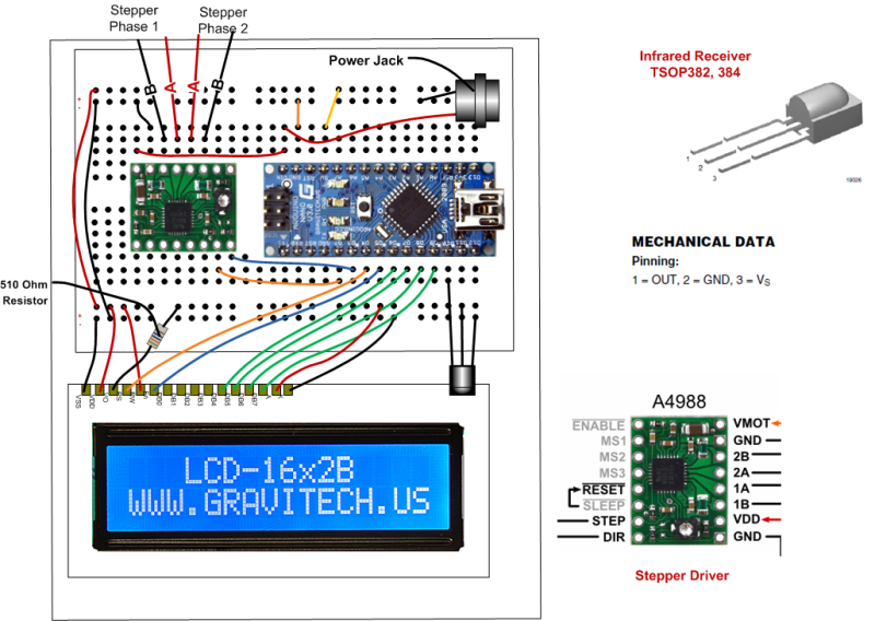
As a matter of interest, this is an alternative setup I had for a while...

Stepper%20Controller_zpsm8au04kg.png


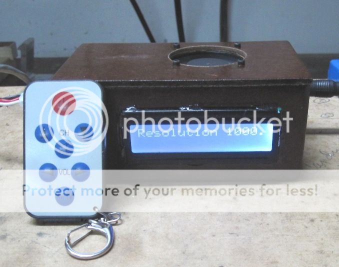
It used an Arduino Nano and a stand alone LCD display. For input, it had an infrared sensor and I controlled it wirelesslely with a keypad like this:

infrared-keychain-remote-500x500.jpg


It used cursor control, much like the keypad version, but the buttons are bigger and I was able to have the arduino and stepper controller assembly sitting on a shelf and control it with the remote. The problem I had with it was that I sometimes had to press a button 2 or 3 times for the sensor to recognize it and there was always a bit of a delay which I didn't care for. If I had worked with it, I probably could have improved it to the point where it was OK, but, being a bit impatient, I went back to the keyed version. However this infrared setup might be of interest to others.

Chuck F.

Edit: Here is a photo of the completed unit and remote.

NanoStepper_zps9e9b309e.jpg
 
Last edited:
Hi Chuck, I was mightily impressed with the way you put this together and so I built one for my Vertex 4".
The only issue I have is the size of the buttons on the 1602 display.Can you please advise how to rewire to a Matrix type keyboard or momentary switches.
Thanks and regards
Miler1
This is the button pad that I used. It will solve all your problems. Buttons are bigger and you can use blue and/or yellow caps on the buttons. Spacing is a little bigger and it uses the same resistor voltage devider. Simple three wire hook up. http://yourduino.com/sunshop2/index.php?l=product_detail&p=334

Let me now what you think. Carl
 
Great topic! Thm:

For the test I used parts of keys from old electronic devices.

CAM00378.jpg
G]​

Red key = Reset

I think the Arduino keys too small for any practical use. When all device buttons that I plan to use will be these:

image.jpg
 
Chuck,
I have copied your sketch However it only runs one direction. I'm using uno wih the Sainsmart shield and a tb6560 driver. Your picture seems to show you using pins 3 and 4 although the sketch says pins 2 and 3. I have EN-, CW-, and CLK- going to ground. Could you help me with the hookup for the CW,EN, and CLK
I appreciate any help you can give me. I'm going to adapt this to a 5c spin indexer.
Thanks

Ritch
[email protected]
 
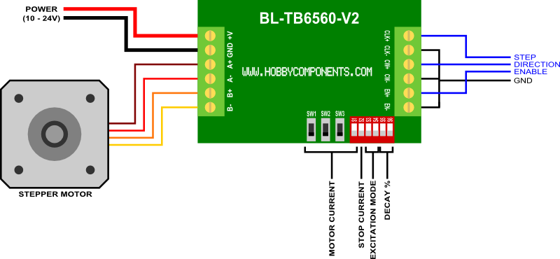
I'm not familiar with the details of the TB6560. Does your TB6560 look like this one?

HCMODU0022_BL_TB6560_V2_Single_Axis_Stepper_Motor_Controller_Diagram.png


If so, pin 2 of the Arduino should go to CW+, which sets the directon, and pin 3 of the Arduino goes to CLK+, which causes the motor to move 1 step. The EN+ is connected to +5v. The sketch must first write a 1 or a 0 to Arduino pin 2. This just sets the direction of spin. Then the sketch must write a 1, delay a few milliseconds, then write a 0 to arduino pin 3, instructing the stepper to move 1 step.

Let me know if this works.

Thx...
Chuck
 
Chuck,

That is exactly what I am using. I copied your text sketch and followed your posted picture. CLK goes to pin 4 and CH goes to pin 3. After the hookup, everything works as it should. Thanks for the help.

Ritch
 
Hi Chuck

I want to use your design as a simple dividing head but also use it on my
rotary table.
Problem is its a 90:1 worm drive so with a 200 step motor thats far to many steps to
wait for (18000).
Can you see any problem by going the opposite way to how you did it and where you used 1:5 gearing on your dividing head to give you 200 X 5 = 1000steps I could use
say 10:1 with the larger gear on the stepper and the smaller on the end of the worm drive to give me 200 /10 X 90 = 1800 steps which although still a lot is
sure better than 18000

Don
 

Latest posts

Back
Top