Electronic Dividing Head using the Arduino

Home Model Engine Machinist Forum

Help Support Home Model Engine Machinist Forum:

This site may earn a commission from merchant affiliate links, including eBay, Amazon, and others.
Hi Chuck

I want to use your design as a simple dividing head but also use it on my
rotary table.
Problem is its a 90:1 worm drive so with a 200 step motor thats far to many steps to
wait for (18000).
Can you see any problem by going the opposite way to how you did it and where you used 1:5 gearing on your dividing head to give you 200 X 5 = 1000steps I could use
say 10:1 with the larger gear on the stepper and the smaller on the end of the worm drive to give me 200 /10 X 90 = 1800 steps which although still a lot is
sure better than 18000

Don

Hi Don,

The biggest issue with your idea is the amount of torque required of the stepper. You'd almost certainly need a larger stepper motor and controller to drive the rotary table through that kind of gearing.

Chuck
 
The Arduino can easilly manage 18000 pulses per revolution. The stepper controller I used on a 90:1 rotary controller was a 10x microstepper so I run at 180,000 steps per Rev using my code which is published elsewhere on this forum. I don't see any reason that Chuck's code can't keep up as I did some testing with similar code. In my experience, the maximum speed will be about 4 rpm (limited by the stepper motor, not the gearing or stepper controller unit) but I have milled circular slots at this speed and it was fine.

In relation to torque, this is related by the voltage you use to drive the stepper motor. I was missing steps at 19 volts on a small 1.5" long NEMA23 (laptop power supply). I purchased a new NEMA23 stepper motor double the length and a 48V power supply. With the higher voltage power supply, I still to this day have not needed to use the larger stepper motor as the added voltage fixed the issue. I reccommend you check your stepper motor specs and choose the correct voltage power supply.

Finally, I will say that best practice is ramping up to speed rather than operating at a fixed speed right from the start like Chuck's code does. This allows you to start moving within the stepper motor's maximum torque range so you can do more with less (to get over the initial inertia on startup). Experimentation is required to set the correct ramp up speed range. My sketch allows you to do this without recompiling.

Rod
 
Thanks Chuck and RODW

I had worried about the torque needed for the higher gearing and also the holding torque needed to stop the work backing up which is why I posted
to ask advice

but with regards to Chucks advice , I wasnt planning on using the pololu drivers as I
have several MSD 542 drivers ( 4.2Amp ) so can easily use a stepper with a higher torque such as the double length Nema 23s that I have and I do have 24 and 48 volt PSUs so I suppose I could still use the revese gearing if I choose to go that way

and to RODW . it was the ability of the arduino to provide pulses fast enough that concerned me . I assumed that sending 18000 pulses would take forever although thinking about it , most of the time I would use the unit to cut gears so would only be moving a fraction of a revolution each time and therefore it would be far less pulses sent . I will have a look for your code as the ability to use accleration is good .
In the past I have tried starting a stepper at high speed and had skipping but starting slower and accelerating did work

Thank you both for the replies . I will have another think about it

Ultimately I would like to put an encoder on the mills spindle to control the speed of the rotary table and be able to hob gears . I once saw a post from John Stevenson about doing this so will have to have a look for it again

Don
 
A quick question for rodw

When you used your code with the 90:1 rotary table what gearing did you use between
the stepper and the RT ? was it still 5:1 like Chuck uses or was it just a direct 1:1 drive

Don
 
A quick question for rodw

When you used your code with the 90:1 rotary table what gearing did you use between
the stepper and the RT ? was it still 5:1 like Chuck uses or was it just a direct 1:1 drive

Don

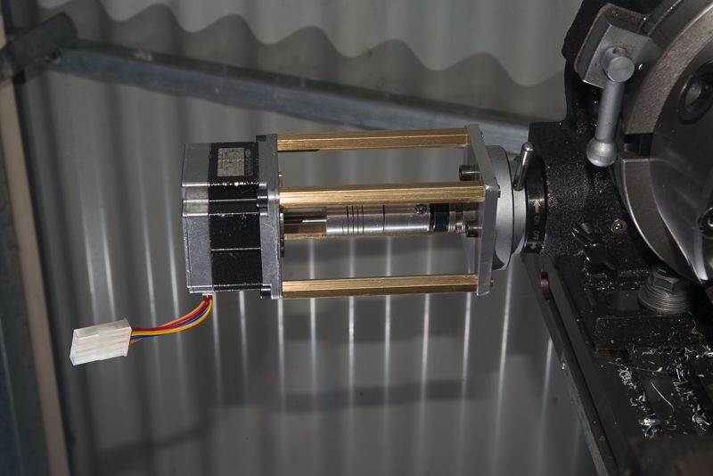
I used a straight 1:1 connection for my rotary table. You can see below, its a pretty small NEMA23 and I have a NEMA17 that has almost identical torque.

DSC_5254_zpse71c8778.jpg


The Arduino is capable of 8,000,000 pulses per second. It has a 16 Mhz clock so its timer interrupt is called 16,000,000 times per second and a complete on/off cycle requires two clock cycles.

I don't want to take anything away from Chuck's work as he was the inspiration for me to do this and I got carried away building a better mousetrap because with what I wanted to do, I wanted to use interrupts which is the most efficient way to generate pulses.

I played with the Polou. It can handle 35 Volts but only 2 amps which in turn requires a heatsink mounted on the driver chip and if it gets too hot, it shuts down. Having said that, heaps of people have used them for Rotary Tables.

I read that doubling stepper input voltage quadruples torque. I'd try and run a Polou around 28-30 volts but 24 volts might do the trick.
 
One quick clarification to what rodw said... higher voltage only improves torque when the motor is turning. It does not increase holding power when the stepper motor is stalled. Torque is controlled by current (amps), so at a dead stall, voltage plays no part in torque at all, particularly since the stepper controller usually limits the current to a preset value. When the stepper is turning, it is generating a counter EMF to the supply voltage. So the faster the stepper is turning, the higher the counter EMF, which decreases the current, which decreases the torque. Thus, using a higher supply voltage keeps the current higher as the stepper motor speed increases.

So as rodw correctly states, usually increasing the supply voltage will increase the maximum speed and the amount of torque when the stepper is turning.

Chuck
 
Thanks both for the excellent answers

It was just after asking Rod if it was direct drive that I felt a bit silly because
I realised that with 90 : 1 on the RT . 10 micro steps and a 200 step motor
using 180,000 steps had to be direct drive , the maths prove it to be so

As I said in an earlier post I wont be using a Pololu type driver , I have some
MSD 542s which will handle 50v @ up to 4.2 Amps , I will probably use
24v the same as I did on my cnc router but I have 48v PSUs too if needed
The drivers have 15 different microstep rates form 2 to 128 and 5 to 125.
They also have the ability to cut the power to 60% if they receive no pulses for
more than 1 second , That helps the motors to stay cool
I will try to attach a data sheet of the driver

Don

View attachment msd542-microstepping-driver.pdf
 
I get "mismatch byte 0x000 0x!=0v0c
Avrdude verification error:content mismatch
 
I get "mismatch byte 0x000 0x!=0v0c
Avrdude verification error:content mismatch

Sounds like you have a config error in your environment, go back to basics and see if you can compile and run the simple starting sketches like hello world.

There have been enough people running this code to know its not a problem with this code.
 
Hi all,

I have just recently come across this thread and am keen to make myself a setup, based on Chuck's great work. I have the Arduino, LCD shield, and driver module on order...

Somewhere, I have some stepper motors, but I have no idea where they are at the moment, but I'll dig them out soon...

My question is to do with the software... Chuck's software is designed to work with two options, a 1000 step for the dividing head and 14400 for the RT. If I wanted to add a third option for say a 40 turn dividing head, would I just add a line to the code like this?

Existing code:
#define stepperDiv 1000.0 // Stepper Resolution
#define rotaryDiv 14400.0 // Steps for 72 turn rotary table

Modified code:
#define stepperDiv 1000.0 // Stepper Resolution
#define rotaryDiv 14400.0 // Steps for 72 turn rotary table
#define dheadDiv 8000.0 // Steps for 40 turn dividing head - all assuming a 200 step stepper motor...

Then modify the following code:

Existing code:
void setup()
{
lcd.begin(16, 2); // start the library
do
{
lcd_key = read_LCD_buttons();
if( lcd_key == btnUP ) numSteps = stepperDiv;
if( lcd_key == btnDOWN ) numSteps = rotaryDiv;
...

Modified Code:
void setup()
{
lcd.begin(16, 2); // start the library
do
{
lcd_key = read_LCD_buttons();
if( lcd_key == btnUP ) numSteps = stepperDiv;
if( lcd_key == btnDOWN ) numSteps = rotaryDiv;
if( lcd_key == btnDOWN ) numSteps = dheadDiv;
...

The idea is that I can select either the stepperDiv by default, or by successive presses of the button, select either the rotaryDiv, or the dheadDiv. Pressing the up button should return to the top of the list.

I'm reasonably confident about the first code mod, but not at all sure about the key reading part... I should have learnt to program years ago, but now I can't figure it out. :wall:

Assuming this is correct (which I doubt), would this then give me the option to select whichever of the three options I want to use? And, assuming I could add more options, is there a limit?

Thanks in advance.

Best regards,

Duncan
 
By the looks of that code, you've only read the button once and assigned it's value (up or down) and you're then evaluating the IF statements in order. In the case of a down value, the first IF will be false and not executed but both of the following IF statements will execute as they are both true. So this would set numSteps = dheadDiv (overwriting numSteps = rotaryDiv which is selected first) every time the button read is down with no way to select rotaryDiv.

Just looking at that small snippet of code, I'd guess you'd need to implement a counter variable and increment/decrement it with each button press to have more than 2 options. With a counter you could add as many options as you want.
 
Thanks guys,

I guess I have some experimentation ahead of me - and a steep learning curve!

The trouble is that this sort of coding is all gobbledegook to me. I can code CSS and html, so I should be able to get my head round this, but none of it makes sense at the moment. When I have the hardward set up and working with the existing code, I'll work something out, probably by trial and error....

Thanks again

Duncan
 
Duncan, the code is set up to toggle between one of two options. Trying to implement more than 2 options is going to require pretty substantial changes to different parts of the program. Obviously the simplest change to use your 40 turn table would be to replace the 14400.0 value with your 8000.0 value.

Chuck
 
Once again thanks for the response guys.

I'm sorry, but the code in your message RodW is meaningless to me at this time. Chuck, I can more or less follow your code - I don't yet understand it, but I'll use it for now.

It's important to me to be able to have an idea of what the code is doing, even if I don't fully understand it! I will try to understand the code in due course, but I'm not sure I will be able to... I should explain that I had a minor stroke earlier this year and, while I'm ok, I find it difficult learning new things - that and I'm not as young as I could be :)

Questions for Chuck please; :)

I have a 40:1 dividing head and a 90:1 rotary table, so can I put in the values of 8000.0 and 18000.0 without changing anything else?

In other words, can I just amend the two lines as shown?

#define stepperDiv 8000.0 // for 40:1 dividing head - could I change stepperDiv to dhDiv, or dividingheadDiv?
#define rotaryDiv 18000.0 // for 90:1 rotary table

I presume that it doesn't matter which value I put first. It will, if I understand it correctly, default to the value entered on the first line, requiring a down button action to select the alternative value. Am I right?

Thanks again!

Duncan
 

I have a 40:1 dividing head and a 90:1 rotary table, so can I put in the values

#define stepperDiv 8000.0 // for 40:1 dividing head - could I change stepperDiv to dhDiv, or dividingheadDiv?
#define rotaryDiv 18000.0 // for 90:1 rotary table

Thanks again!

Duncan

Duncan, nothing wrong with Chucks soultion.

A #define in C is simply a way to write understandable self-documenting code. Statements on a line commencing # is an instruction to C's precompiler and does not generate any CPU instructions. So whenever stepperDiv is in the code, it will be replaced by 8000 or 18000 depending on the value when executable code is generated.

But where do these numbers come from is what you need to ask on your path to enlightenment!

Most stepper motors take 200 pulses (steps) per revolution but this is not always the case. You do the maths but you will see why they are referred to 1.8 degree steppers if you divide 360 by 200. Some steppers are 0.9 degrees.

So if you have a 90:1 worm drive, it is going to take 90 turns of the motor to turn the table 1 revolution or 200 x 90 pulses = 18,000

So with your 40:1 worm drive 1 revolution will require 40 x 200 pulses = 8,000 pulses.

The other parameter that comes into play is if your stepper controller is microstepping. The Gecko 251x is a popular example. It is a 10x microstepping controller so it takes 2000 pulses to turn the stepper motor one revolution.

So if you were using one of these stepper controllers, you would need to multiply these values x 10 to get
90:1 180000
40:1 80000

So back to the C world, by convention #defines are shown as upper case to make it clear they are not variables. I would prefer to set defines like this:

#define STEPPER_STEPS 200 //200 steps per revolution drive
#define WORM_DRIVE 40 // 40:1 worm drive
#define MICRO_STEPS 10 // 10 x microstepping ( 1 if no microstepping)
#define STEPS_PER_REV STEPPER_STEPS * WORM_DRIVE * MICRO_STEPS

So now all you have to do is fill out the variables and C does the calculations for you. Just use STEPS_PER_REV instead of stepperDiv and when you revisit the code or share it with somebody later it is 100% clear what is going on.

One day you will understand my code if you play with C long enough. It is complex, but clear and concise. The very first version I posted does it all in 200 lines of code. Then I got carried away..... The flip side is the user does not need to change any code.....
 
Hi RodW
Wasn't there a problem encountered with counting such large numbers of pulses? something about "rounding" number of steps or pulses ?
Perhaps this was only in Chuck's original sketch.

xpylonracer
 
Once again thanks for the response guys.

..... (deleted)

I have a 40:1 dividing head and a 90:1 rotary table, so can I put in the values of 8000.0 and 18000.0 without changing anything else?

In other words, can I just amend the two lines as shown?

#define stepperDiv 8000.0 // for 40:1 dividing head - could I change stepperDiv to dhDiv, or dividingheadDiv?
#define rotaryDiv 18000.0 // for 90:1 rotary table

I presume that it doesn't matter which value I put first. It will, if I understand it correctly, default to the value entered on the first line, requiring a down button action to select the alternative value. Am I right?

Thanks again!

Duncan

You are correct. Simply changing the two values will make the program work with your dividing head and rotary table. You can change the names to something more meaningful to you, just be careful to change those name in all parts of the program that reference them. My approach to programming, after 50+ years off and on, is to change the program as little as I can get away with to make it do what I want.

There are some things in the code that may not be clear. For example, the math had to be worked out to ensure that rounding errors would cancel out as the spindle or table turns. In other words, I had to be sure that one full revolution would always return to the starting point. I'll take a look at the code to see if I can add some comments which might make it easier for you to understand. I do love programming and try to keep it as simple as I can, mostly so I can go back a week or two later and understand what I was trying to do! :confused:

Chuck
 
Thanks Chuck! Your help is appreciated, as are the comments from other members... :) :thumbup:

One more question - or maybe a few...

I want to be able to cut gears up to 127 teeth - Boxford Imperial to Metric screw cutting conversion...

Can you, or anyone, suggest how many steps I need in 360 degrees to achieve this accurately?

You stated in your earlier posts that with 1000 steps you should be able to accurately handle 30 divisions, so would 4000 steps get me to 127 divisions? Can this be achieved by microstepping? If I use a 5:1 gear reduction like you are using and ¼ steps?

Alternatively, I have been looking at Nema 23 motors with epicyclic gearboxes and can get 15:1 and 27:1 easily - and reasonably priced.... Do you think one of these would be better, with direct drive to the spindle? Holding torque would not be an issue with such reduction gearing...

I'm not worried how long it takes to rotate from one position to the next, it's not a quick job turning the handle and ensuring the right number of holes are advanced each time on my dividing head - and it's all too easy to make a mistake! :rolleyes:

This is all new to me, so I apologise for all the questions....

Duncan
 

Latest posts

Back
Top