Arduino RPM Application for Sieg Lathes and Mills

Home Model Engine Machinist Forum

Help Support Home Model Engine Machinist Forum:

This site may earn a commission from merchant affiliate links, including eBay, Amazon, and others.
Very cool but sadly I can't play as my SX3 mill comes with a tacho readout...
 
Having just come across this thread read it with interest as I had a similar problem. With a lathe driven by a 3ph motor controlled by a VFD fitted with a variable resistor giving outputs set from 10 to 70 Hz available at a twiddle of the fingers and a belt variator incorporated within the belt drive I hadn't a clue what speed the chuck was whizzing around at. I didn't have the ability on my lathe to do what Jenny had done, if I had the Jenny's solution would have been magic, but fortunately another forum pointed me in a different direction.

From Hong Kong via E-Bay I purchased a 4 digit display mounted on a controlling pcb and supplied with proximity sensor and magnet for about £6.50. Delivered. Where was the profit in that I thought. Then I went to Maplins (we had one then) and bought a cheap plastic enclosure for about £4. I made up an attachment to fit in the end non-working end of the headstock that is secured by a simple expansion arrangement (so it can be very easily removed it it is ever necessary to mount something in the chuck that fits all the way back through the headstock) and Araldited the magnet to that, mounted the sensor to suit and wired it into the pcb together with a 12v dc supply and away I went. The tricky bit was finding out what wire went where, as there were no instructions!

So, 2 pics below to show read-out and sensor mounted on the end of the headstock.

Hope you don't mind me taking your thread on a little detour Jenny.

Chris

IMGA0679.JPG
fullsizeoutput_d8e.jpeg
 
Last edited:
Great job Chris,

Not only do I not mind, I am happy that this post piqued enough interest to get others to think of their own solutions.

It amazes me how inexpensive electronics from the Far East are. It opens up a whole world of experimentation on a shoestring budget.

I also thought about a pickup/magnet solution but having been a software engineer, and having stumbled over someone else’s work where he had decoded the signal from the controller, I decided to just use the data available from the controller board on my machine.

Now that you bought up how inexpensive the display and other components are, it makes me wonder just how Axminster can justify charging £150.00 their display?

Well done Chris, a nice solution.
 
Thanks for your kind words Jenny. Am impressed with your software capability and knowledge, to me it's a black art; as a mechanical guy I am also always suspicious of anything with wires coming out of it!

Yes, electronic stuff from the Far East does seem very inexpensive, how they do it for the price inc. delivery I don't know, but happy to avail myself when I need to, so the high prices some UK supplies charge for stuff is upsetting and seems unjustified. £150 for the equivalent of what you did does seem just a tad over the top!

We live about an easy half hours drive from Axminister and about 10 years ago I was always eager to visit the Axminister store there. Not anymore, now I only go if I desperately need something I can't get elsewhere. Then they had a good stock of metal mangling tools and equipment, now very little, they seem to be more interested in folk that play with that brown stuff rather than metal. Pity really. Their service and delivery are as always first class, but they seem to have very limited stock of engineering stuff and have seem to have gone 'up-market' engineering-wise, which is code for the same stuff at much higher prices. Sadly, despite Axminster being on the doorstep I use ArcEutoTrade for most stuff these days; they, I find, are more reasonably priced and their service and delivery is also excellent plus they cater for a wide range of workshop engineering needs.

Chris
 
Yes I agee with your view of Axminster, but i am guilty of having bought one of their 500 watt 7x12 lathes, and an SX2 vertical milling machine from them. I think I liked the colour scheme better ;-)

lately I have purchased much of my tooling, and accesories from Arceurotrade. They are much more reasonable. i thimk I picked up my ER32 collet set from them for about 1/2 price as well.

However I have found making one more jump "ustream" in the supply chain and purchasing directly from the makers saves me even more. If I see something I like at ARC or AXM and the brand name is visible, I simply search for the makers company on-line and buy direct. Great customer circus is worth a lot from a supplier, but not a 100% markup.

For example I purchased my replacable carbide insert tooling direct from Glanze at less than half the price AXM asks and 1/3 less than ARC. I use their mutiple insert fly cutters, and lathe tools. i have also found great end mills both carbide and steel from others at much better prices as well.

OK thats enough off topic blather for now...
 
Someone from the Axminster forum that I also posted about my Arduino project did a lot of work getting my code to run on an Arduino NANO.

He posted his experiences there, so I thought I would pass it along to this forum.

Jenny


Hi all,

As I was looking for a way to set up a tachometer on my mini-lathe and mini-mill, I stumbled upon this post. It was a great relief: what I wanted already existed and was described in great details. So I asked Jenny about this code and she kindly answered me and sent it to me very fast. Then, I started to play with it.

I decided to use an Arduino nano rather than an Arduino Uno so it could fit within the lathe enclosure, with a window cut on the top for the display. As the LCD screen takes almost all the space in the top panel, this implied moving the green power indicator and to remove the yellow fault light. One consequence of moving the fault LED was to add a new feature to the tachometer so it replaces this notification: I wanted the LCD monitor the fault line and display a “FAULT!!!” message message when needed. As the Arduino nano can use interrupts on only two pins, I therefore started by moving around the pins: yellow positive wire to pin2, LCDCL to pin 3, LCDCS to pin 4 and LCDDI to pin 5. With this setting, I could use one interrupt for the LCDCL (clock for RPM data transmission) and another interrupt for the fault line.

I also wanted to change the interrupt routines to use a more explicit API, using attachInterruptinstead of EIMSK/EICRA/SIGNAL(INT1_vect)that were used on the original code. In the Interrupt Service Routine, I also wanted to reduce memory usage by extracting only the single LCDDI bit (instead of the full 8 bits PIND register). This failed dramatically! I tried a lot of different things in the past few weeks and was not able to achieve my goal. It seems to me that despite the board will be idle most of the time (the rotation rate is refreshed only every 750ms), when it is refreshed the bits arrive fast and the board has a hard time coping with the interrupts. The ISR must therefore be really really short to remain fast enough. I also failed simply replacing the SIGNAL(INT1_vect)declaration with a call to attachInterrupt, but this failed too, and here I don’t understand why. I thought it was only an API change and an overhead to pay only once at setup, but it seems to be also more costly when servicing the interrupt. I basically gave up there. So the handling of the fault line is just done by checking the pin status at the top of the loop routine, without using the interrupt that should be available on pin 2. I don’t like this solution and it seems to sometimes displaying the fault message even when the spindle is rotating… I think however that when I did these tests the pin was not connected and so a floating input may take random values. I will probably have to check this again now that I have rewired everything.

During my numerous tests, it occurred to me that the board missed about two third of the refresh! When using a serial console, I got about one RPM message for two communication errors. As the code was mixing some polling/delay part with interrupt-driven logic, I tried to tighten that a bit, removing the delays and using a circular buffer to allow bits to avoid dropping bits if the loop happened to be run in the middle of a message. In this case, we would have just returned, preserving the partial message received so far and have wait for next call was the circular buffer was still filling up with bits. This failed too. It requires an ISR that can fill up a circular buffer and I think the nano was not powerful enough to do it when the bits stream arrived. It failed despite the circular buffer handling was only a few instructions long with index bits masking to wrap up at the end of a buffer whose size was a power of 2. Losing 2 refresh out of 3 is not the end of the world. When using the lathe, looking at the RPM display is not the main activity. When trying to control the proper speed I simply need to stay a few seconds before the display stabilizes. I can cope with this.

So I went back to Jenny original code with only very few changes (currently the FAULT part was also commented out despite the wire is connected).

The advantages of using a tiny board, shoving it in the lathe enclosure and having only the LCD display sticking out are:

  • it takes less space on the headstock
  • there are no risks it will slip and drop with vibrations
  • there’s no need to buy an enclosure
  • there’s no need to buy a special plug
In order to do the connections, I only had to cut the wires and crimp in some salvaged female headers into which the male headers from the Arduino nano plug in. I protected the remaining pins of the nano by putting heat shrink everywhere. I may also use some hot glue to prevent the headers from falling in case of vibrations.
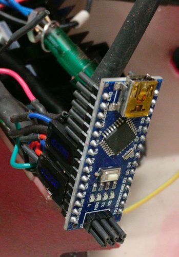

Y

I also wrapped the board in a plastic bag before shoving everything in the enclosure.
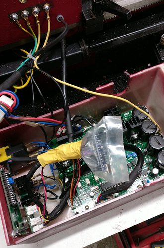


Cutting the window for the screen and putting the screws in the right place was quite a challenge because I could not move the enclosure to my mini-mill: it was to tall. I cut the window freehand with a Dremel tool. The following image shows the back of the LCD screen mounted on the top surface of the enclosure. It takes the location of the green power light, the yellow fault light, and the LCD socket.
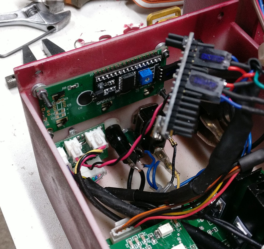


One can hardly see in the previous image the green power light that was moved below the forward/reverse switch and the main fuse. Desoldering the green power light and resoldering the wires after the move was also tricky as the other end of the wires is connected to other wires, thus preventing the soldering operation to be performed conveniently: one as to do it within the enclosure. I later noticed that I cut the window for the LCD screen slightly too close to the opening
(i.e. too close to the spindle). When mounting the enclosure back to the headstock, it almost
touches it.

As is, it works, thanks a lot to @Jenny for sharing this, it helped me tremendously.
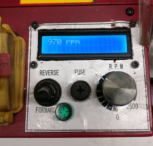


For my training, though, I think I will continue to investigate the software changes I wanted to make initially, perhaps using a more powerful board. I purchased the nano boards from China using Ali Express marketplace. The boards costed only 2€ each (maybe this is the reason the boards cannot keep up…). I will try with other boards I purchased from Mouser the ESP32 pico Kit <https://www.mouser.fr/_/?Keyword=ESP32-PICO-KIT>. The provider is more reliable and the ESP32 is far more beefy, probably even overkill for this application. The cost also remains very reasonable (8.73€). Programming is quite different from Arduino, so I will have to change a lot of things.
 
Great work, Jenny! I look forward to making my own based on your excellent work. I'm going to try for a 320X240 display with touchscreen so it will be a little more involved.
 
please share what you learn about using the touch screen with us.

My next step was to integrate an input device so one could enter a material and It’s diameter then have the program suggest a speed.

too bad the controller will not accept a digital speed input. If it could, and I’m not sure it can not, then the application could set the desired speed.

have fun,
Jenny
 
Just an update,

Since first posting this project I have had over forty people who have contacted me for the code or advice complete this project.

some have successfully used the Arduino “Nano” boards and were able to contain everything inside the existing housing of their lathes and mills, while others built it in a separate enclosure.

I am glad so many of you have enjoyed this quick easy build.

jenny
 
Hi Jenny followed your tacho thread with interest. I have an SX3 CNC Mill which wiped out its electronics with a shorted touchpad to earth. (Many have suffered)
It is now rebuilt with new Sieg components but the Display readout reads half of the spindle RPM. This annoyed me so I thought of a different approach, Many of the contributors to this thread are probably using Mach3 which has an Index input to read the rpm of the Spindle for display and closed loop operation.
I had to replace the three Hall effect Sensors on the DC Brushless Spindle Motor, £4 versus £400 for a new motor, as part of the repair and had a look at the output pulse on a scope. One pulse per rev. The Sieg CNC BOB is optically separated on inputs so why not piggy back one of the Hall Sensors to the Mach3 Index input.
I found this works accurately but only after applying a factor of 4 to the pully entry in the software, despite the mill being 1:1 for which I have no answer.
Controlling the spindle is another matter I have yet to solve. I can start and stop but controlling the rpm is not there yet. There is pages on other boards on the subject.
 
Sometimes a Hall Effect sensor is a bad choice. A reed switch will handle the speeds associated with our mills and is essentially bulletproof. We use them instead of the hall sensors in low-speed model IC engine ignition systems.
 
Hi Bob,

In response to your statement:

“I have yet to solve. I can start and stop but controlling the rpm is not there yet. There is pages on other boards on the subject.”


I thought about controlling speed by replacing the potentiometer used now to manually control the speed with a voltage regulator chipset and then manage the speed thru an Arduino application. There are lots of examples that can handle it in the R/C vehicle world.

perhaps set the desired speed with a keypad, then use the output from the rpm application to regulate it. At That point it would be a snap to take it a step further and write another application to determine desired speed based on material, diamete, and cut depth in the case of a lathe, or material, type of tool and depth of cut with a mill.

while it would be a fun thing to do it may be overkill considering most of us are just hobbyists taking light cuts with the way underpowered Sieg equipment we use.

Jenny
 
Hi Jenny yes I agree. I have now accomplished most of what I aimed to achieve. The piggy backed Hall effect sensor needed some averaging and a pulley ratio applied as there are four pulses per rotation (Not the one I had previously stated) from the Sieg Motor. Still trying to achieve a speed ratio that does not stall the motor on startup but so far looks promising and a very cheap way of creating a closed loop spindle control. Electrical Noise is definitely a problem with these machines there are no screened cables just a couple of ferrite rings. Having 240 Volts close to the touchpad is another horror story. Thanks for the comments
 
Thanks for the code. I did a variation tweak on an 0.96" oled display, as that's what I had in the draw. Code is attached if anyone wants that. It's in Platform.IO project format, thought the base code is the same as Arduino.
 

Attachments

  • MiniMillTach.zip
    2 MB
Not sure if this is of any interest to anyone, but: my latest version uses a 4 digit LED "Digital Tube", with my adaption of the original code from MacPod/Jeffrey Nelson on an ATtiny84 piggy-back board. Using this, I only need to mount the display somewhere, and attach one cable to either the 7-pin XH header on the original control board, or via the standard Sieg GX16-7 socket.

(My version of the software allows the rpm to be read by another Arduino, via I2C; it's intended for integration into a home-brew Touch-DRO controller...but that's a whole 'nother topic.)
 

Attachments

  • ATtiny84Tacho_front.jpg
    ATtiny84Tacho_front.jpg
    300 KB
  • ATtiny84Tacho_back.jpg
    ATtiny84Tacho_back.jpg
    247.1 KB

Latest posts

Back
Top