Dave's twin

Home Model Engine Machinist Forum

Help Support Home Model Engine Machinist Forum:

This site may earn a commission from merchant affiliate links, including eBay, Amazon, and others.
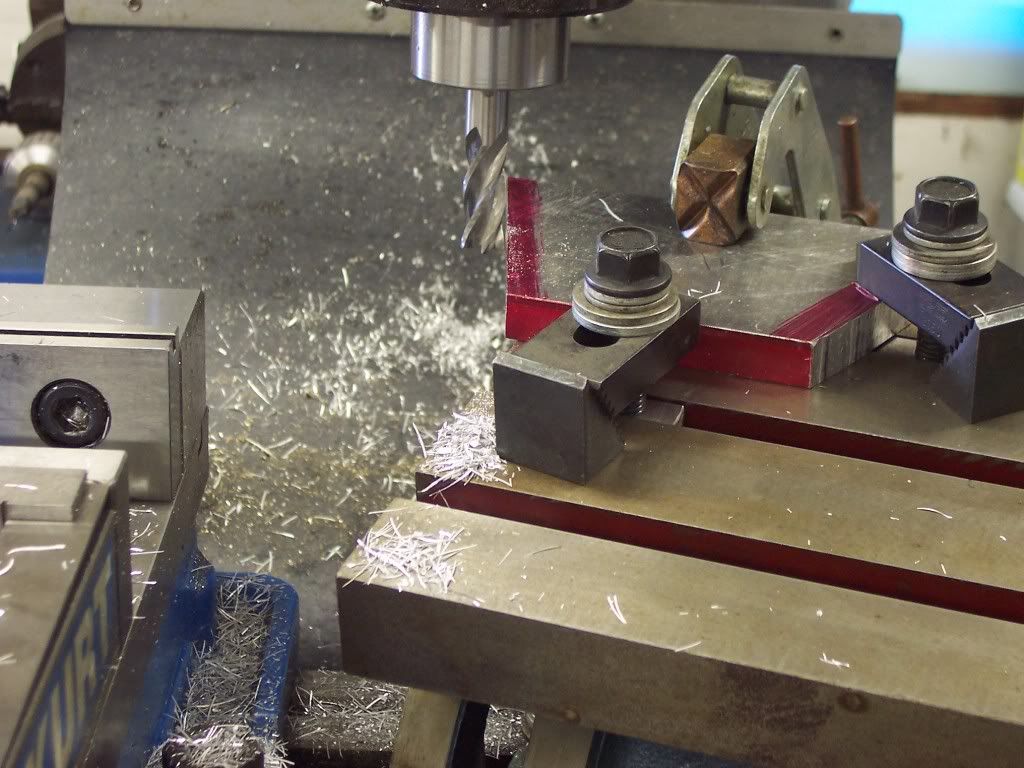
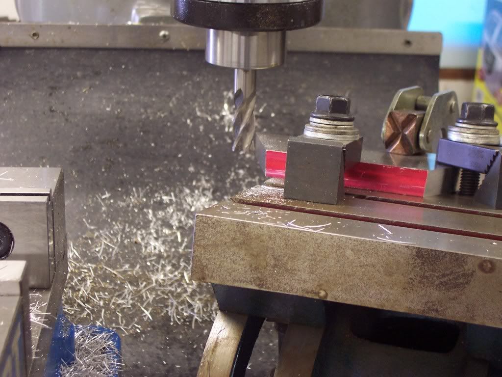
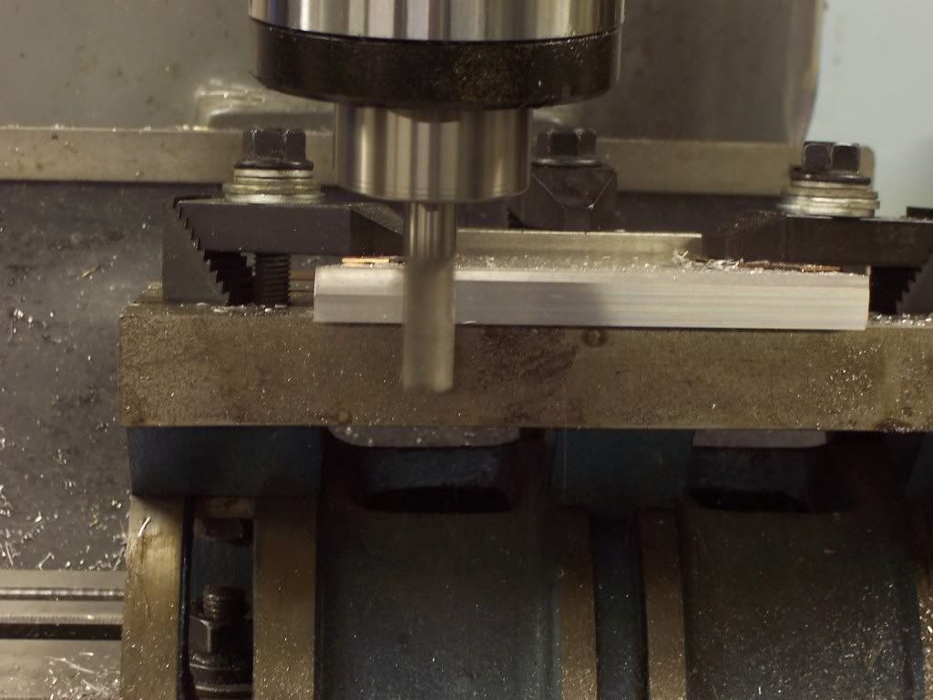
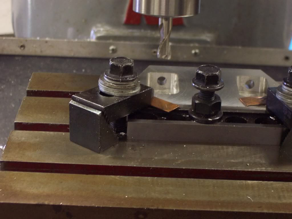
The end of the rocker that get the roller needs a groove milled into it. A 3/16" endmill was used.
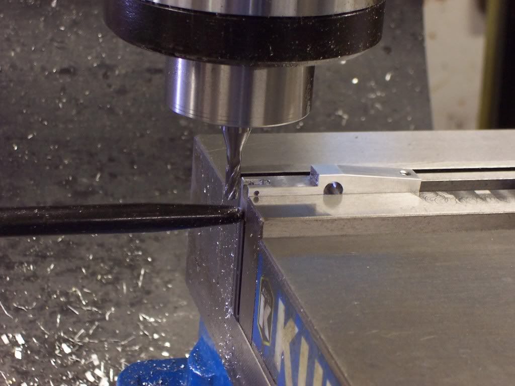
102_1225.jpg


Once the mill cuts were made the rockers needed to be radiused on the die filer. I used the belt sander to rough the surfaces in and then went the die filer and then finished with paper. A few clearance cuts were needed for the intake valve and then the rockers were debuured and sanded smooth.
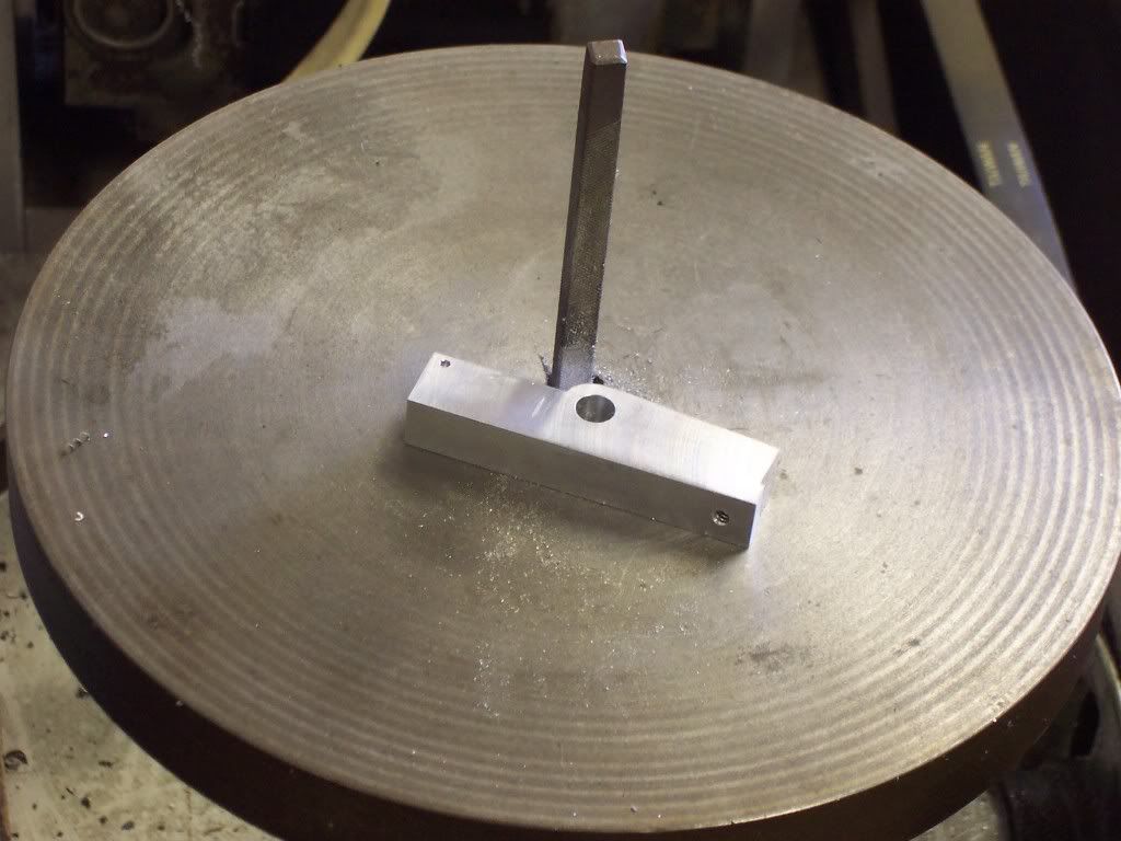
102_1226.jpg
 
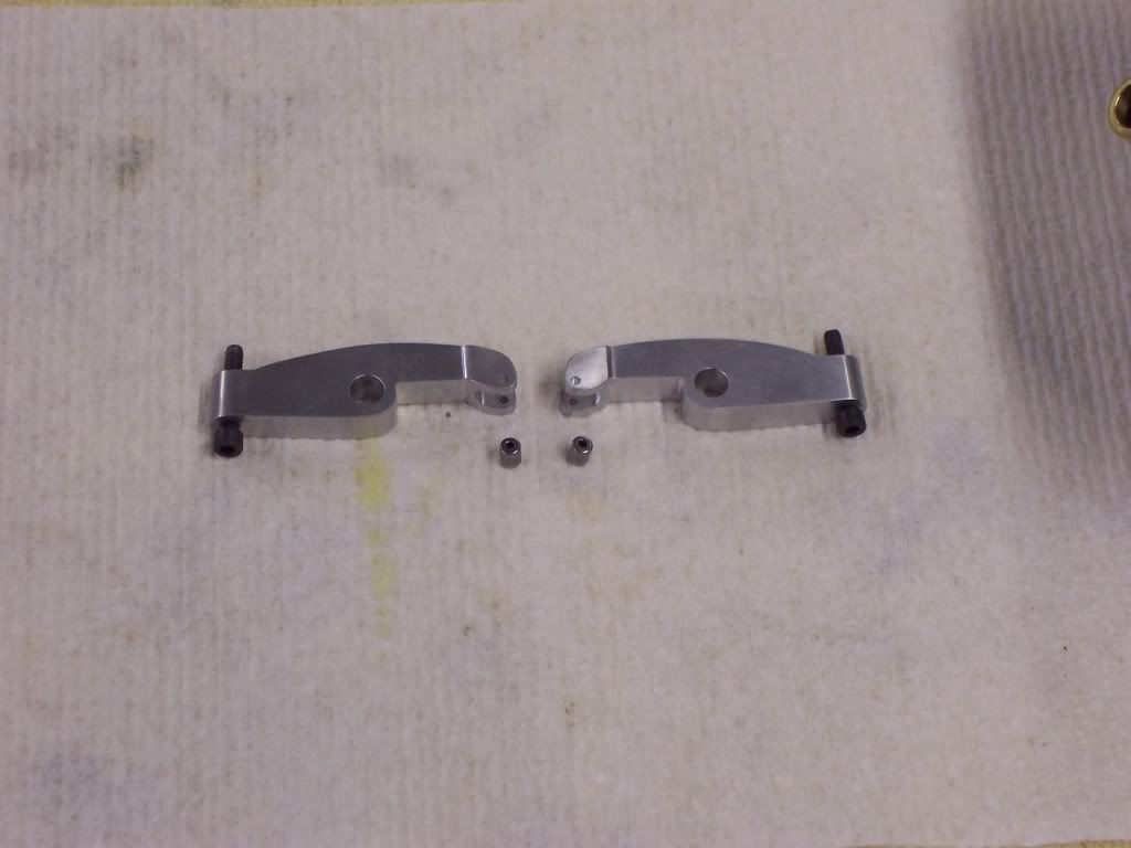
A pic of the rocker arms with the rollers. The rollers came from the scrap bin and were from an old roller bearing. They were drilled with a .0625" dia carbide drill for the center hole.

102_1227.jpg


The rocker stands will come next and then the heads will have to be modified for the stands.
 
Thanks Steve and Chuck. I'm glad you are following along.

Peter, the die filer was made from a set of MLA castings. Metal Lathe Assesories. I bought the castings about ten years ago but I think they are still available. This has got to be one of my favorite and most used tools. Because I have no CNC capabilities, if I want any odd contours I have to belt sand them and then I go to the die filer. I normally finish with sandpaper but the die filer is a good medium between the belt sander and the hand work. I recomend this die filer as a good useful project. Dave
 
After a couple of weeks of warm weather, and getting nothing done in the shop, it has decided to get cold again which drove me back into the shop. I made the rocker stands and modified the heads for them but due to operator error no pics came out. Next came the intake manifold.

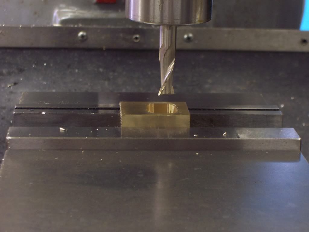
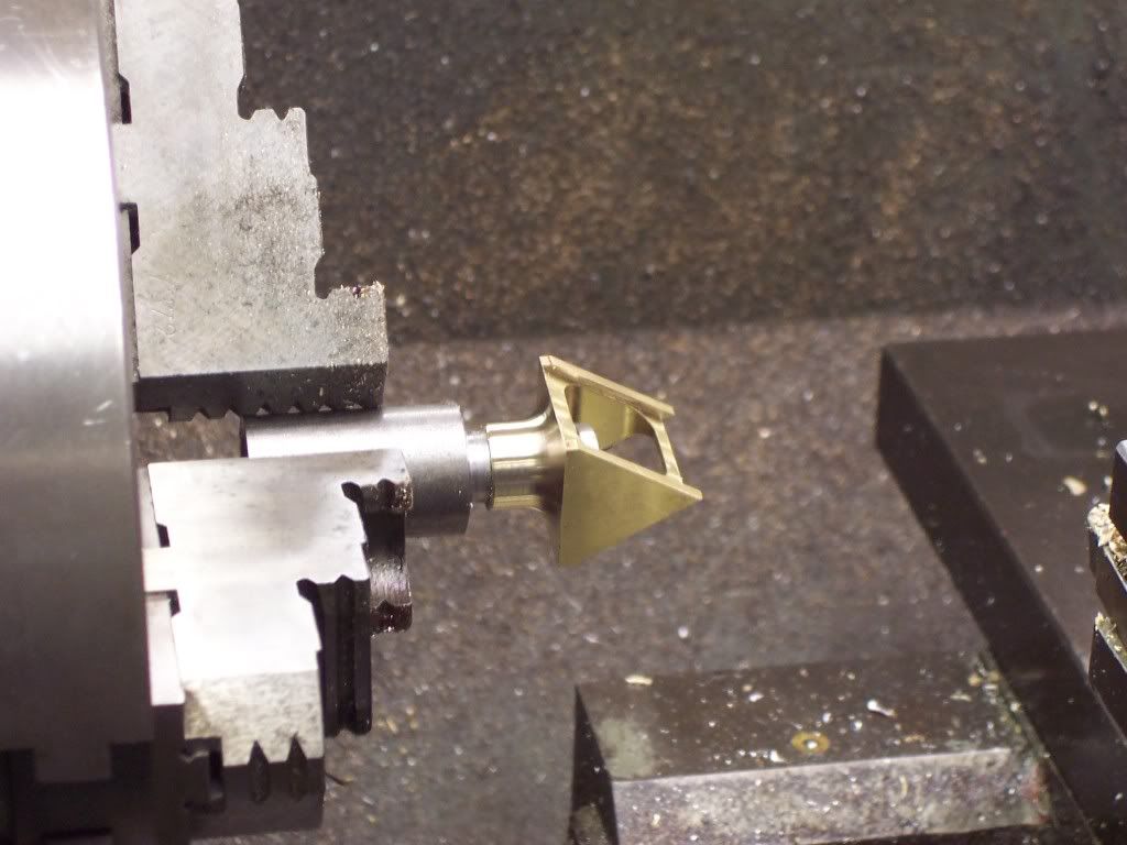
I started with a piece of brass 1"x1"x1.4". After the piece was squared to size a window needed to be milled into the part. A 3/8" endmill was used after drilling a pilot hole first.

102_1228.jpg


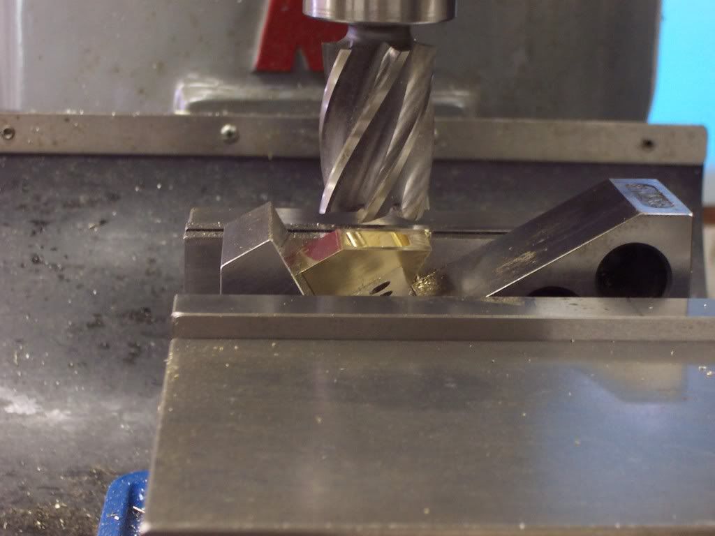
The bottom of the piece needed to be milled on a 30 degree angle on each side. The piece was setup in the mill vise using my 30 degree angle block and then the piece was milled to size and then flipped over to do the other side.


102_1229.jpg


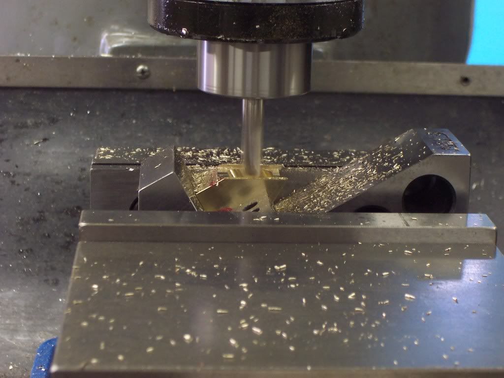
While the part was still in this setup I needed to mill a .05" deep groove in each side for the side plates to fit into.

102_1230.jpg
 
Now I needed to turn a spigot on the top end for the carb to fit into. The piece was setup in the mill vise and indicated to find center.
A .344" hole was reamed thru the top surface and then deburred. A piece of CRS was put into the chuck jaws of the lathe and an arbor was turned to size so the manifold would slide onto this arbor and would be secured with a 1/4-20 bolt. A radius tool was used to backcut the spigot dia.

102_1231.jpg


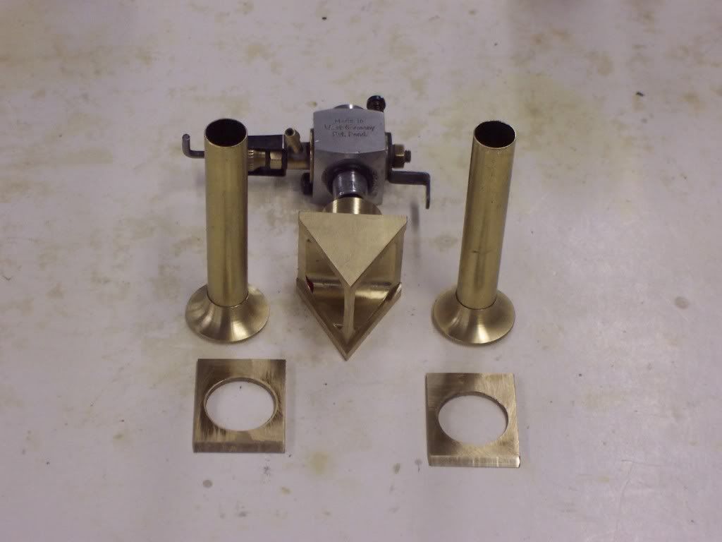
Heres a pic of all the manifold pieces before soldering them together. The center plenum will have 2 sideplates. The 3/8" dia tubing has the adapters slid onto them. The adapters have a generous radius on the entrance to the hole so the mixture has a smooth surface to flow around. This is also the carb I intend to use.

102_1232.jpg


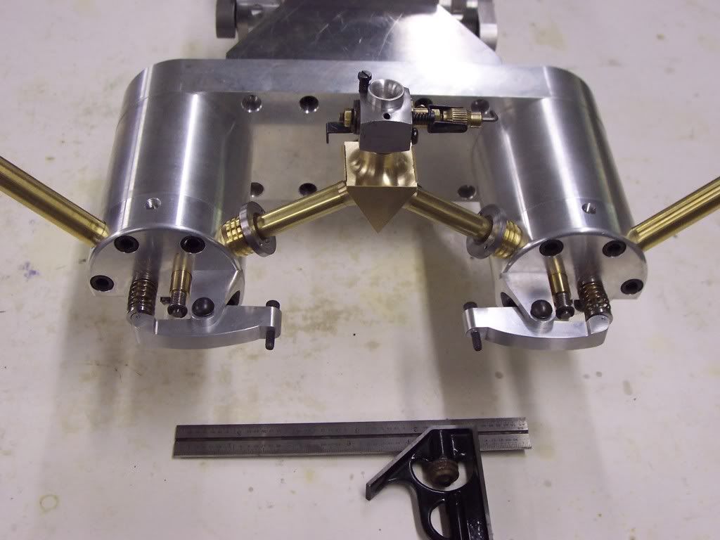
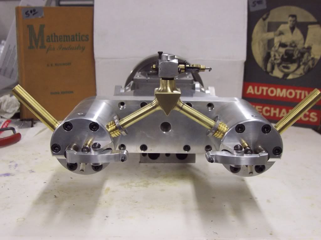
A pic of the engine with the intake manifold in place before soldering. The combination square is for reference and is 6" long.

102_1233.jpg


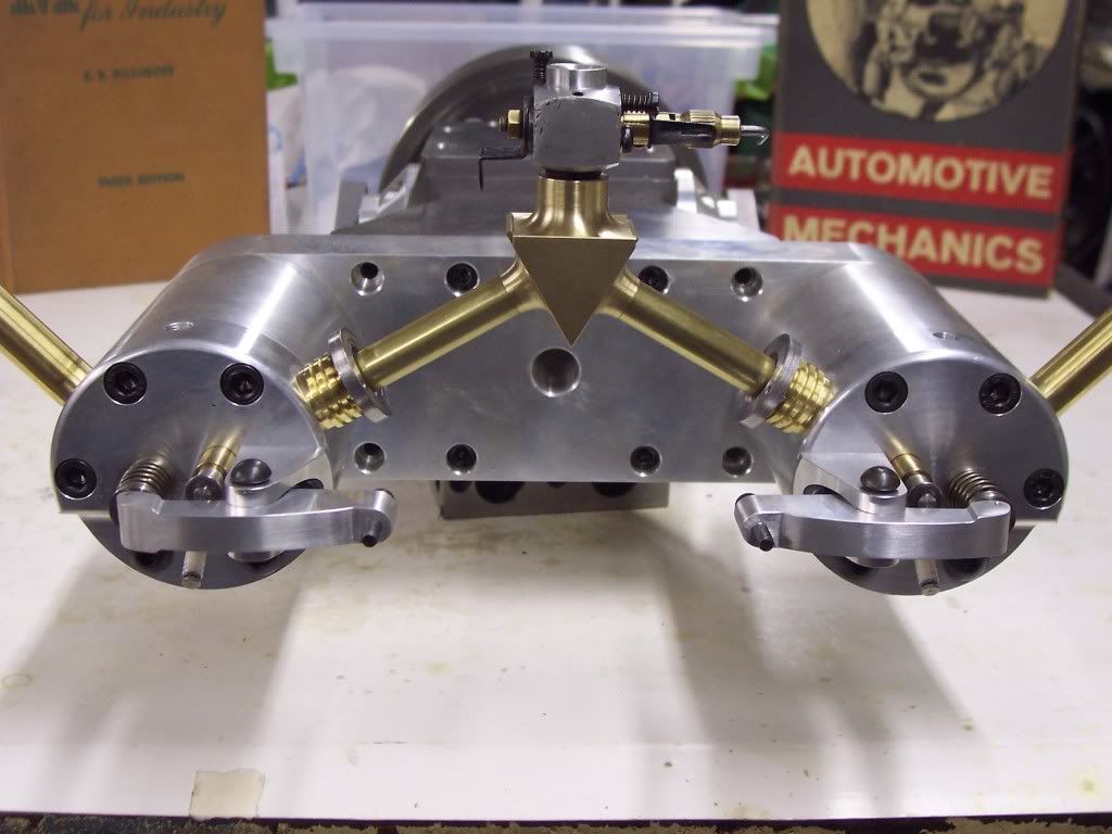
And a front view pic.

102_1234.jpg


The tubes will be secured by retainer clamps that still need to be made and will be sealed with o-rings. After the manifold is soldered I will radius all the edges to smooth the look of it. I wanted to have a small plenum under the carb for better distributing the fuel mixture and I think this will work alright. We will see.

Also in this pic you can see the rocker arms and their stands assembled to the heads. When assembling, I will need to install one head and then place the manifold and then install the other head.
 
That intake manifold is a work of art on its own. And the whole setup looks great.

I am still following with admiration.

Jim
 
Now that's cooler than the other side of the pillow!!! Great work and thanks for the update. The warm temps here have kept me busy outside too, but today the rainy weather has given me some inside time, maybe I'll do something?!?!?!

Craig
 
She's coming together very nicey Dave. Good tip on honing the valves in the lathe.
 
Thanks guys, I'm glad you're following along. Got some time tonight to do some soldering and finishing. The intake manifold pretty much finished.

102_1235.jpg


It doesn't look like I'm going to have this thing ready to run before the NAMES show but it will be there. I am going to make the support legs next and then a base. I better get humping or I'll need a milk crate to set this thing on. Dave
 
The support legs were made from .5" thick 6061 al. They were squared up to size on the mill then clamped to my adjustable milling table. The table was set at 10 degrees and then the part was clamped to the table. I had scribbed a line on each end for reference. I used a pointer in the drill chuck and positioned the table with the line perpindicular to the x axis of the mill. Once the line was true the table was tightened to the mill table. One end on each support was milled to the scribbed line.

102_1236.jpg


To cut the other ends the table had to be set at 10 degrees in the other direction. The parts were inverted and milled to the line.

102_1236.jpg
 
Oops, duplicate pic. heres the one I should have posted.

102_1237.jpg


The top and bottom edges needed to milled at a 10 degree angle next. The adjustable table is repositioned to be parallel with the x axis but is still set at ten degrees.

102_1238.jpg


The mounting holes were drilled and then they needed to be relieved so the head of the bolts had clearance.

102_1239.jpg
 
I had to disassemble the engine so I could drill and tap the mounting holes in the gearcase. While it was setup I also tapped a 1/16-27 pipe tap for a drain plug. I didn't want the legs to just extend from the gearcase at a 90 degree angle so they were milled at a 10 degree angle to give them a little wider stance and I thought it would look better. A pic of the engine with the legs attached.

102_1241.jpg
 
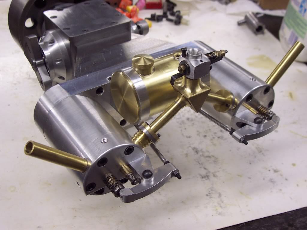
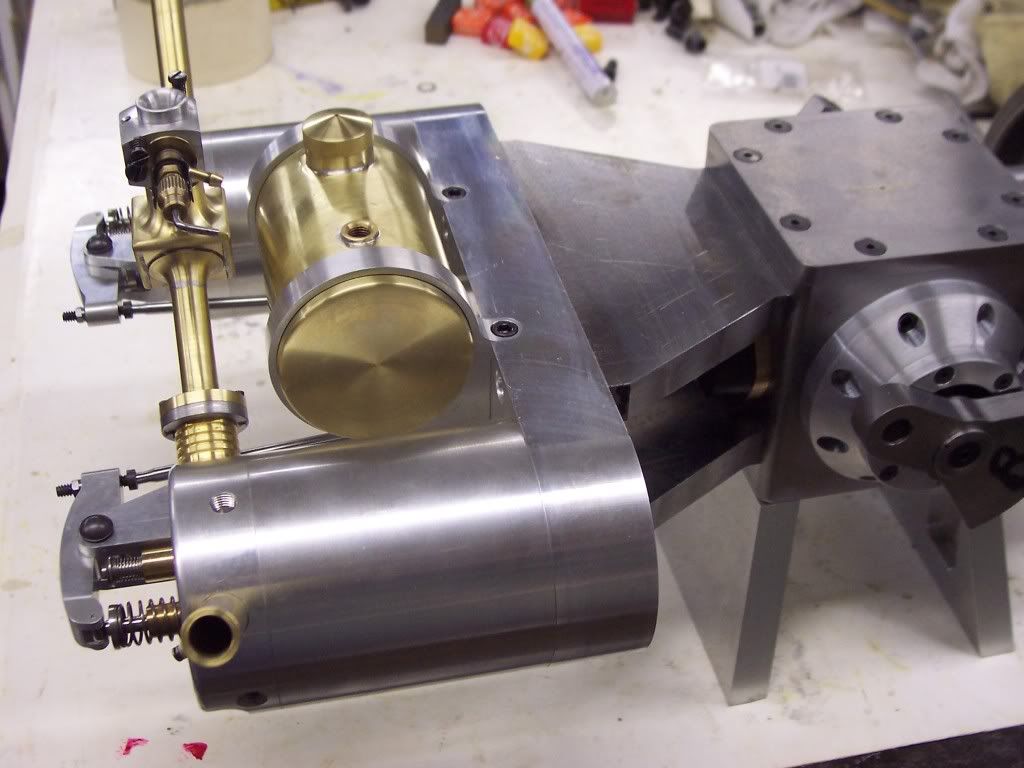
Haven't had much time lately to work on the twin but I did get a few things done. I made the intake pipe clamps and the pushrods. I also found some time to make the fuel tank and it's holder.

102_1244.jpg
 
A different view of the fuel tank and it's mounting.

102_1243.jpg


The intake pipe clamps will sandwich an o-ring which will seal the intake pipes to the heads. The fuel tank was made from a piece of brass tubing that previously spent alot of time inside a drinking establishment ( bar rail ). I found a couple pieces of this at an engine show a few years back and I should of bought more of it.

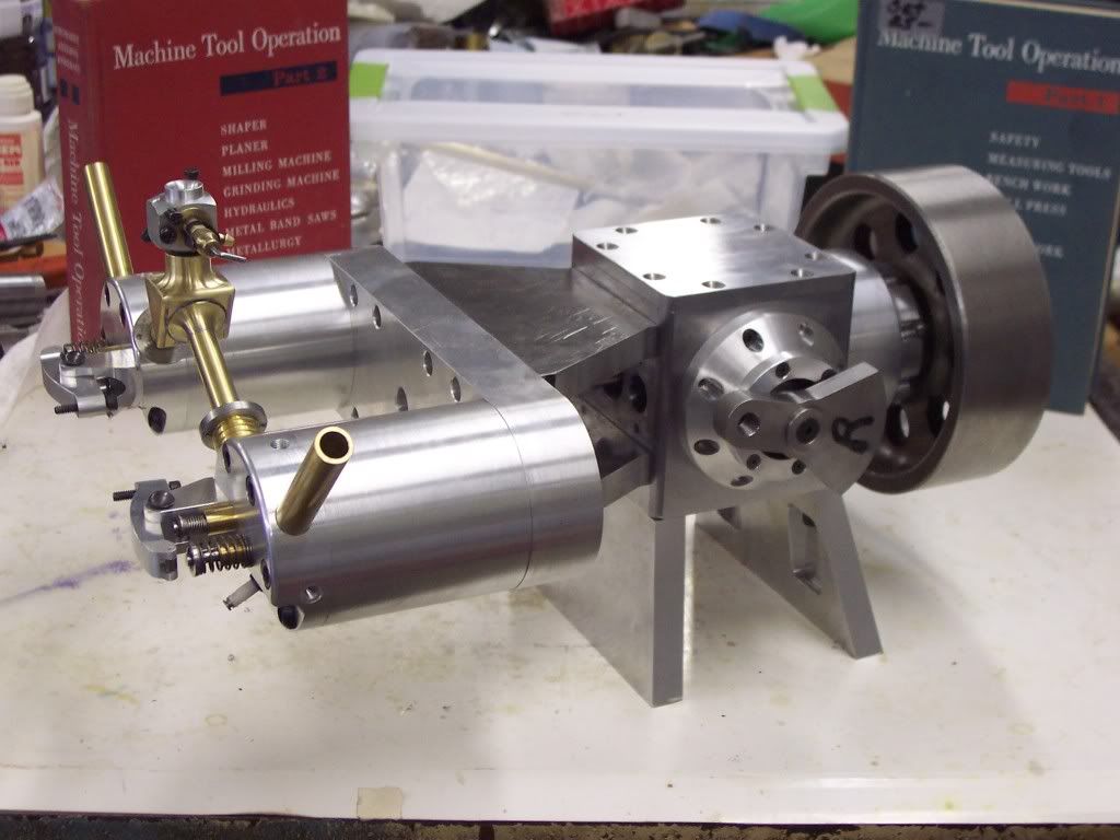
The cam seems to open the valves as they should when the flywheel is turned. I made the rocker arms so the pushrods and the adjusters are in a straight line at half of the valve lift. The Starbursts in the background were compliments of the Easter Bunny. Dave
 
Very Very nice!
So are the inlets atmospheric, I canna not see whats working them

Mark
 
Thanks Mark, the intake valves are atmospheric. My hopes are that this engine will be a slow runner. Dave
 
Back
Top