Build pictures of GB 4 cylinder overhead value engine

Home Model Engine Machinist Forum

Help Support Home Model Engine Machinist Forum:

This site may earn a commission from merchant affiliate links, including eBay, Amazon, and others.

gld

Well-Known Member
HMEM Supporting Member
Joined
Jun 18, 2009
Messages
176
Reaction score
89
Location
Tarkio, Missouri
Some members wanted to see a build thread on my construction of Geroge Britnell's 4 cylinder overhead value engine. I did not take any pictures of actual machining setups. So here you go with what I have so far.


This is the first group picture I took.
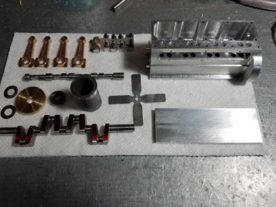
normal_4cyl_parts.jpg


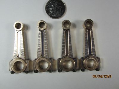
The con rods are bronze. I just happen to have a section of bronze bushing stock 3"OD X 1-1/4" ID left over from repairing a dozer years ago. I cut a slice off and milled to the proper thickness. Then I draw a 3" circle in cad with id of 1-1/4" and placed 4 rods and caps in that circle. The code was generated in Fusion360 and they were cut on my home made CNC router. You can see that machine here. http://www.gldpages.com/CNCRouter.htm
normal_Rods.JPG


After they were cut out I used a rotary table to do the profiling.
normal_Rods1.JPG


The rocker arms were constructed in same manner as the rods and profiled on RT.
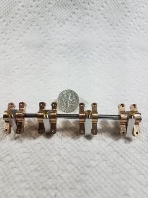
normal_20191121_165052.jpg


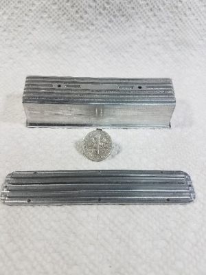
Here is the value and tappet cover.
normal_20191127_111135.jpg


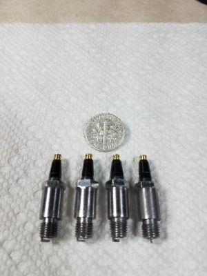
And here we have the spark plugs.
normal_20191119_100749.jpg


This is the last group picture I took.
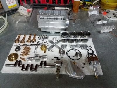
normal_20191006_154902.jpg


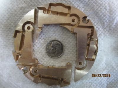
The timing gear cover and distributor cap were also CNC'd on my router.
 
I built that same CNC router in 1999. It has served me well but I would like to fit a spindle more suited to cutting metal like you have done. Nice little engine, I will be following along.
 
That's a cool little engine. Very nice work!

Are there plans available for George's work? I couldn't readily find them with Google. This looks like something up my alley in the future.
 
That's a cool little engine. Very nice work!

Are there plans available for George's work? I couldn't readily find them with Google. This looks like something up my alley in the future.
You will need to message George directly to purchase a plan set. As far as I know they are not for sale on any website.
 
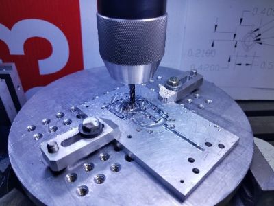
Well, I guess since some fellows got me posting, I just as well keep it up until this project is finished. Today I finished the exhaust pipe flanges. Here I m profiling on the RT.

normal_20200816_1618055B15D.jpg


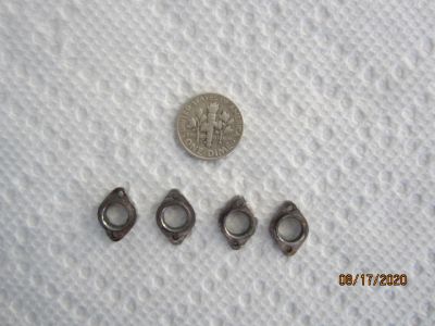
And the finished product.

normal_IMG_0673.JPG


Thanks every one for the kind words.
 
As Gary stated, send me a personal note and I will give you my drawing list and information.
 
Very nice precise work. Has the engine been assembled and run yet? Thank you for sharing.
I just bought my mill yesterday a cx600 from busy bee,and along with my b2229 lathe i am anxious to choose and start a project. Cheers
 
When I try machining things of that size I discover I have ten thumbs, lovely work. Cheers, Peter.
 
Wow - That's an impressive build - keep up the postings.
Like "ten thumbs" Peter, small parts give me the most trouble - the tinier the parts, the worse the imperfections look (and behave) - So I'm impressed.
Regards, Ken
 
that is impressive to say the least, I think that is a lever that I will never get too, saw the video and that is so cute, that would work great in my truck, OK well maybe not, is that free hand or CNC, either way your really good, Joe
 
When I try machining things of that size I discover I have ten thumbs, lovely work. Cheers, Peter.

My biggest problem with machining small parts is not having too many thumbs; it's having too much floor. Inevitably I wind up making the smallest parts multiple times because I drop the blasted part, and even though I watch it carefully as it hits the floor, I still can't find it. At least not until weeks later, and invariable no less than 10 feet distant from the point at which it was dropped.
 
I know what you are talking about, I do mechanic on Lawnmowers, saws and trimmers, if I drop a part sometimes I can find it they will always roll under the work table so I invested in those small pocket extension magnets but the non Ferris is a search that puts one on his knees so I have a stash of parts when one is non repairable when it comes to saw and trimmers with those very small parts its shop towels and very careful movement, some things are designed to jump out of your hands only to find them months later, Joe
 
This past weekend I was making two small tappets, and managed to drop one. I looked and looked where it had fallen, swept with a magnet, and came up empty, other than odds and ends of swarf. Muttering words of grace under my breath (I'm sure that's what I was muttering), I made another one. Then - you guessed it - I dropped that one! I KNOW I watched it all the way down, but once again, looked and swept, and nada. Muttering more words, even more gracious than before, I went back to make ANOTHER one - and found the first one I dropped, half a mile or so from where I dropped it.

Clearly, evil forces inhabit my shop ...
 
Dropped small parts appear to have the ability to defy normal laws of conservation of momentum.
I propose an engine, which consists of a hopper of small parts, about 3 feet above a section of concrete floor with a heavy object on it 10 feet away. A device to capture the energy of the small parts as they are dropped and hurtle lemming-like to the gap under the heavy object should provide enough power for a small town.

Genius!
 
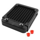
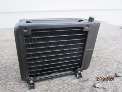
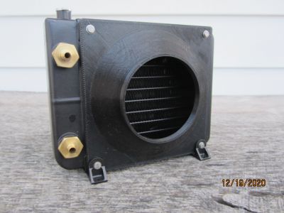
Time for an update on this little engine. I decided not to make a radiator when I found this on Walmart's website. $27 and free shipping, just couldn't turn it down. It’s for a 4” (120mm) computer fan.

thumb_120mm_radiator.jpg


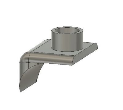
As you can see, there is no fill neck. So got out y radius gauges and measured the radius on the tank. Then I drew up a model in a 3D CAD program.

normal_Radiator_fill_neck.jpg


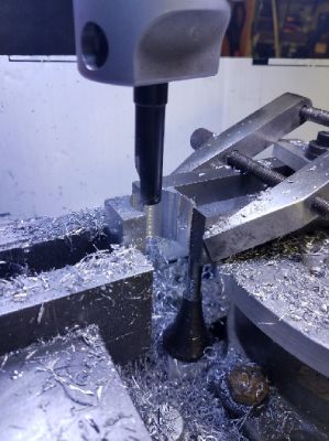
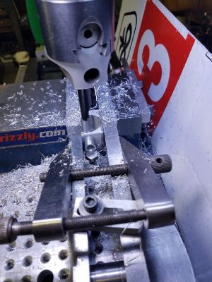
Machining the fill neck.
normal_20200905_093315.jpg


normal_20200905_093246.jpg


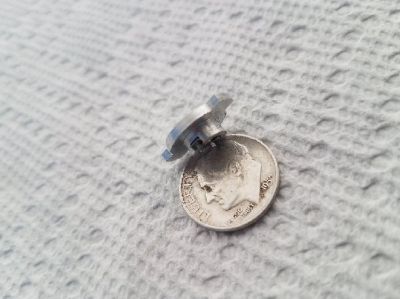
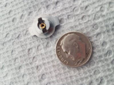
Next we need a radiator cap.
normal_20210104_150409.jpg


normal_20210104_150517.jpg


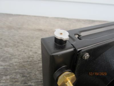
I use coarse sandpaper to sand the paint off of the tank at the top and proceeded to a fix the aforementioned part with J-B Weld. After the JB cured out, drill a hole thru the new fill neck into the tank. And the finished product.

normal_IMG_0677.JPG


normal_IMG_0678.JPG


I 3D printed the fan shroud.
normal_IMG_0676.JPG
 
Last edited:

Latest posts

Back
Top