rake60
Well-Known Member
- Joined
- Jul 8, 2007
- Messages
- 4,756
- Reaction score
- 125
At work, the old Hardinge Automatic Turret Lathes replacement parts are rapidly becoming obsolete.
The antiquated solid state timing relays are a major concern. You can still find them as new old stock
but they run on average, $1000.00 Each of out 4 lathes has 6 of those timers in them, and they do go bad.
All these timers do is control the dwell in time for all of the cross slides. To get consistent sizes from the cutting
tools, the dwells must be for at least the time required for the chuck to turn 1 full revolution.
I prefer to set the dwells for 2 to 3 revolutions.
If the dwell is set too long the tools will burn up from rubbing on the metal.
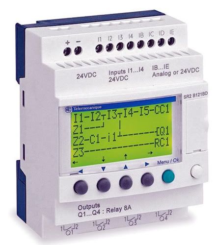
My solution is to replace all of the timers in each machine with a single programmable logic controller, (PLC).
The PLC isn't exactly new technology either, but it's better than what we have now.
I found these PLCs that are manufactured by Telemecanique which is now a a division of Schneider Electric.

The cool part of that is, you can download the software to program that PLC and simulate running those
programs before actually buying the $350 PLC. (That is a 486MB file!)
The programing is Ladder Logic, that I do have some experience with from my previous job.
All of the operating machine cycles in that production plant were controlled by one or more PLCs.
I'm practicing to see if I can actually make it do what is needed. I am pretty sure I can.
Then I decided to play a little and try to make a program that would operate an abbreviated standard
traffic signals green, yellow and red lights.
Green 6 seconds - Yellow 2 seconds - Red 6 seconds.
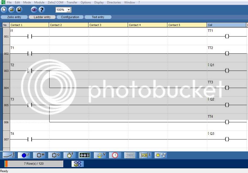
This is what I ended up with in Ladder Logic format.

l's are discrete inputs, TTs are programmable timers and Qs are outputs.
l1 is the only discrete input. It turns the whole program on or off.
TT1 is a timer that is programed as an asymmetrical flasher.
It pulses On for 1 second then turns Off for 13 seconds.
TT2 is a timer triggered by the pulse from TT1.
It is programed to stay on for 6 seconds after receiving the pulse from TT1.
The ladder from TT2 sends a pulse to TT3.
It is programed to stay on for 2 seconds after receiving the pulse.
The 4th rung of the ladder logic send a pulse from TT3 to TT4.
It is programed to stay on for 6 seconds.
As that sequence is ending timer TT1 sends another 1 second pulse that restarts
the program.
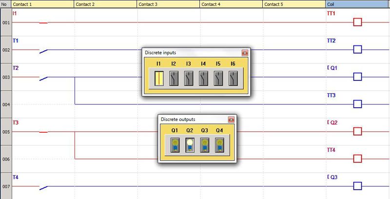
In simulation mode with the program, it shows virtual which inputs and outputs are energized.
It looks like this during the yellow light stage of the program.

I know it sounds pretty "geekish" but it's no different than hitting that size every time.
When it all comes together it feels pretty damn good!
Rick
The antiquated solid state timing relays are a major concern. You can still find them as new old stock
but they run on average, $1000.00 Each of out 4 lathes has 6 of those timers in them, and they do go bad.
All these timers do is control the dwell in time for all of the cross slides. To get consistent sizes from the cutting
tools, the dwells must be for at least the time required for the chuck to turn 1 full revolution.
I prefer to set the dwells for 2 to 3 revolutions.
If the dwell is set too long the tools will burn up from rubbing on the metal.
My solution is to replace all of the timers in each machine with a single programmable logic controller, (PLC).
The PLC isn't exactly new technology either, but it's better than what we have now.
I found these PLCs that are manufactured by Telemecanique which is now a a division of Schneider Electric.

The cool part of that is, you can download the software to program that PLC and simulate running those
programs before actually buying the $350 PLC. (That is a 486MB file!)
The programing is Ladder Logic, that I do have some experience with from my previous job.
All of the operating machine cycles in that production plant were controlled by one or more PLCs.
I'm practicing to see if I can actually make it do what is needed. I am pretty sure I can.
Then I decided to play a little and try to make a program that would operate an abbreviated standard
traffic signals green, yellow and red lights.
Green 6 seconds - Yellow 2 seconds - Red 6 seconds.
This is what I ended up with in Ladder Logic format.

l's are discrete inputs, TTs are programmable timers and Qs are outputs.
l1 is the only discrete input. It turns the whole program on or off.
TT1 is a timer that is programed as an asymmetrical flasher.
It pulses On for 1 second then turns Off for 13 seconds.
TT2 is a timer triggered by the pulse from TT1.
It is programed to stay on for 6 seconds after receiving the pulse from TT1.
The ladder from TT2 sends a pulse to TT3.
It is programed to stay on for 2 seconds after receiving the pulse.
The 4th rung of the ladder logic send a pulse from TT3 to TT4.
It is programed to stay on for 6 seconds.
As that sequence is ending timer TT1 sends another 1 second pulse that restarts
the program.
In simulation mode with the program, it shows virtual which inputs and outputs are energized.
It looks like this during the yellow light stage of the program.

I know it sounds pretty "geekish" but it's no different than hitting that size every time.
When it all comes together it feels pretty damn good!
Rick


