An Upshur Farm Engine (first I.C.)

Home Model Engine Machinist Forum

Help Support Home Model Engine Machinist Forum:

This site may earn a commission from merchant affiliate links, including eBay, Amazon, and others.
Many, many moons ago I used to do software programming as a hobby and I find that it helped me in this hobby also. I think of a complete engine as a software programme. Major pieces of an engine as subroutines and minor pieces of an engine as routines in subroutines. They all have to go together at some point.

When thinking of setups I think of pseudo code.

I always try to put my past experiences to good use in life.

Vince
 
tvoght said:
Marv, you've got me thinking about procedure in this hobby, and how that
relates to my profession (software). I write complex sequences of operations
every day. Surprisingly, I've never thought that much about how that drives my
need to work out and document procedures before going into the shop. I know
that is something that John advocates, too. Maybe I can find a way to make
that more explicit in my posts (you may have noticed how sometimes my
photographed parts are posed over oiled-up procedure sheets).

INMNSHO, the three hardest things to learn in this hobby are, in order of decreasing difficulty,...

Patience and paying attention
Setups and workholding
Operation sequencing
 
It's been a week or so since I've posted, and in the interim I made some valves.
I actually produced at least two useable ones, but I'm not yet completely
happy, so I'm coming back to them after a little thinking break. I started
on the head instead.

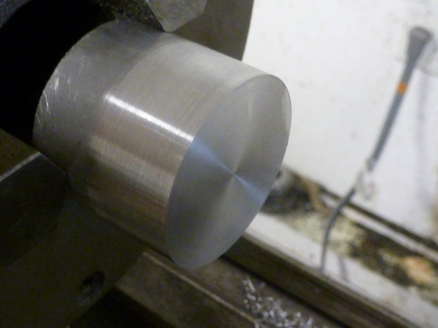
I sawed off a piece of aluminum rod and chucked it up as centered as I could
(my 3-jaw chuck is adjustable). I faced off the end and just cleaned up the
circumference with emery.

5.jpg


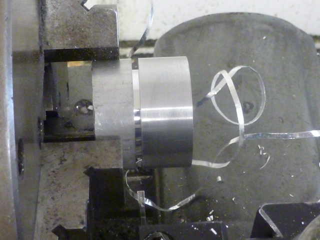
I started a cutoff with plenty of extra length as I plan to finish the cutoff
end on the mill. When cutoff began to be unpleasant, I finished the job with
a hacksaw (lathe turned off).

10.jpg


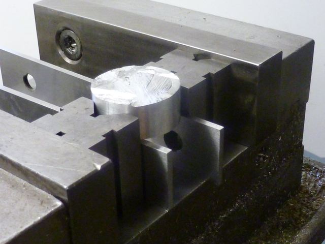
I clamped between v-blocks in the mill vise with the faced end on parallels.
I am kicking myself repeatedly for not providing some shims to protect against
the v-blocks. Like most stupid mistakes there is no real "why". Maybe I'll
know next time? I didn't realize what I'd done until I had performed a lot
more work.

15.jpg


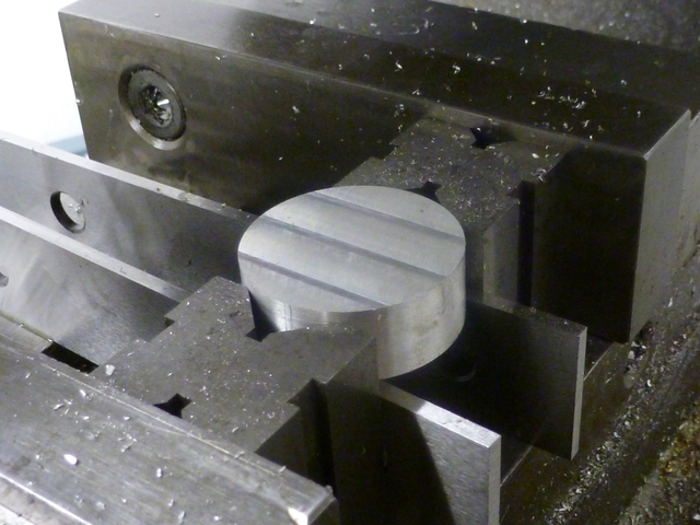
The sawn side was milled to get the head to correct thickness.

20.jpg


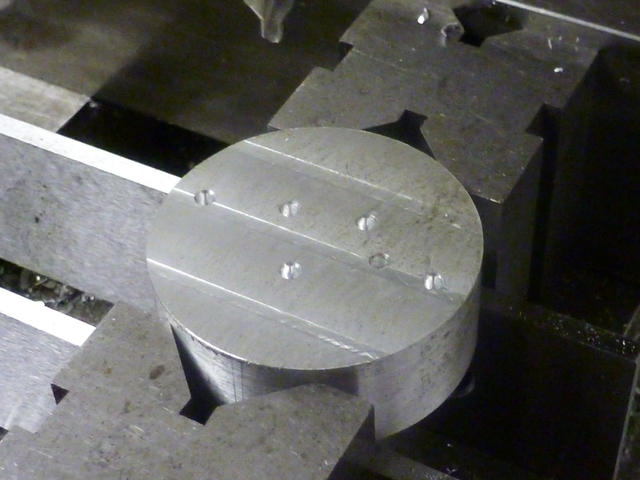
I center-drilled for the various holes I would drill.

25.jpg


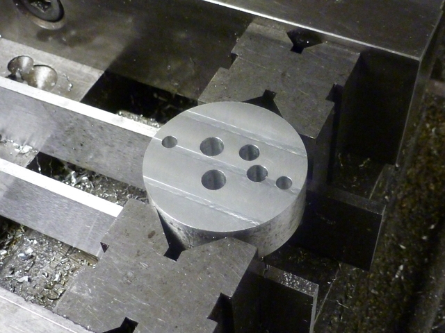
Then drilled the holes and finally reamed the 4 larger ones.

30.jpg


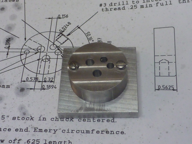
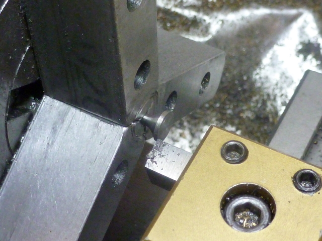
I had previously made a fixture from the MIC-6 tool plate with holes drilled
and tapped for mounting the head. Here it is mounted on the plate. The plate
is as square as I could make it and the head is centered on it.

35.jpg


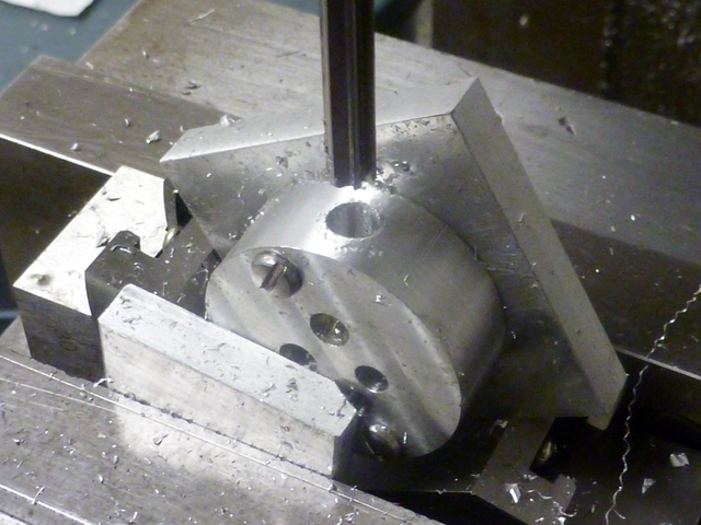
I was then able to use the fixture in the angle block to set up for three
holes to be made around the circumference for exhaust, intake, and spark.
Here I have reamed for the exhaust pipe.

40.jpg


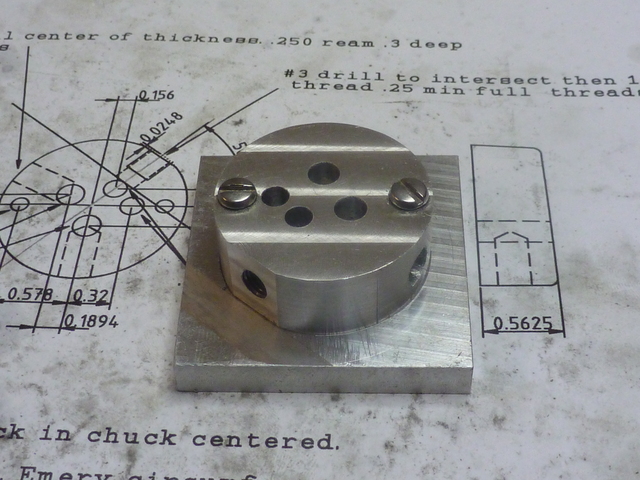
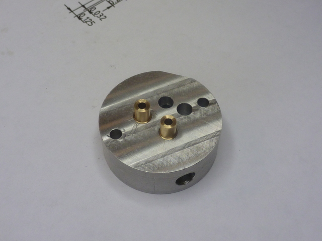
Here's the part still on the fixture plate with all machining (save for the
valve seats) finished. You can see one spot between the plug and exhaust
holes where the v-block dug in.

45.jpg


Thanks for keeping an eye on me.

--Tim
 
Just file the v block marks out. It won't be noticeable once assembled.
 
I was just reading a post by Vince (vcutajar) from today about his making of
the valves for this Kiwi Mk2. Like he, I referenced the excellent postings by
gbritnell:
http://www.homemodelenginemachinist.com/index.php?topic=19103.0
http://www.homemodelenginemachinist.com/index.php?topic=15942.135

My results were not nearly as beautiful as Vince's, though I did create at
least 2 valves that would surely have worked. Mostly, I was unhappy about the
finish I got on the stem and the trouble I had getting a smooth transition
from stem to seating face. The material is 303 stainless. I used a cutting
tool with a relatively sharp point and zero leading angle, this to try and
reduce radial forces and concentrate cutting forces axially along the stem to
prevent flexing. I guess the sharp point contributes to the less-than perfect
finish, resulting in some grooves which are not easily removed with abrasive.

5.jpg


I imagine a little more effort along those lines would have resulted in valves
I was very happy with, but I was also getting bothered by the repeatability of
my efforts (that 2 steps forward, 1 step back sort of feeling). In the
interest of experimentation and trial-and- error learning, I decided to pursue
the idea of a valve machining jig I saw in Issue 7 of Model Engine Builder
magazine. The article describes essentially a combined follower rest and form
tool, the form of which is to cut the underside of the valve head and the stem
at the same time. The tool described had the underside angle ground into the
cutting tool, but I took the different approach of mounting the cutter at the
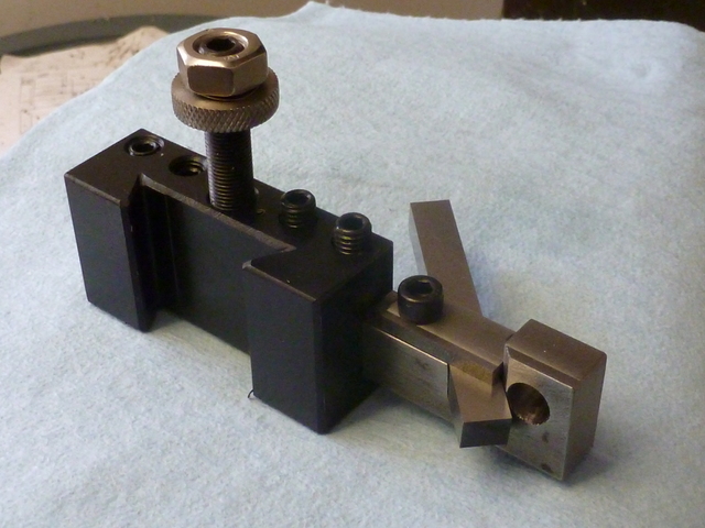
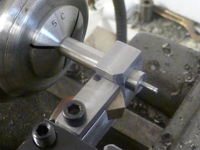
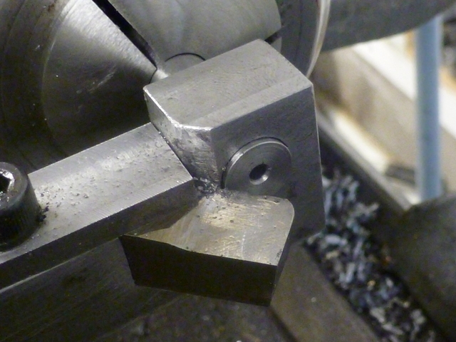
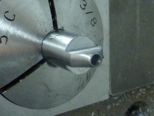
desired 45 degree angle. This made grinding the cutter much easier. Here is the
jig mounted in a QTCP holder. The cutter here has not yet been ground, but you
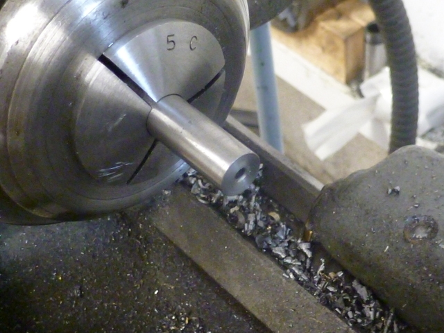
get the idea. The reamed hole closely fits the 3/8" stock which will be held
in a collet.

10.jpg


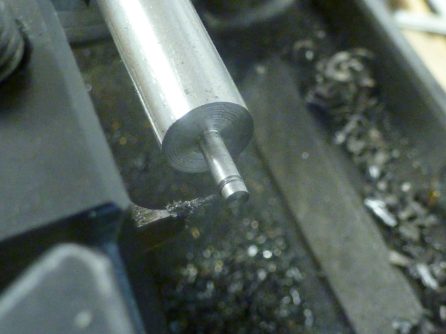
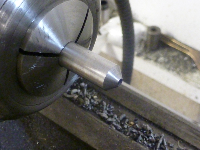
My first step closely follows George's procedure. With the stock in a collet,
I cut a short section down to stem size and cut a groove for an e-clip (the
plans call for the retainer being loctited onto the stem, but this is another
of my departures from plan). Incidentally, I ground the groove cutting tool
myself, and while it's not perfect, it helped to build my confidence in tool-
grinding. It works good enough, and I think next time I can do better! Oh, I
should mention I've gone from 303 stainless to 416 stainless. The 416 machines
better.

15.jpg


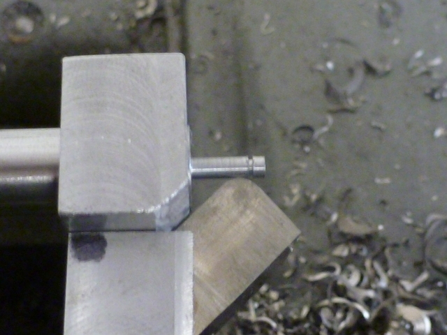
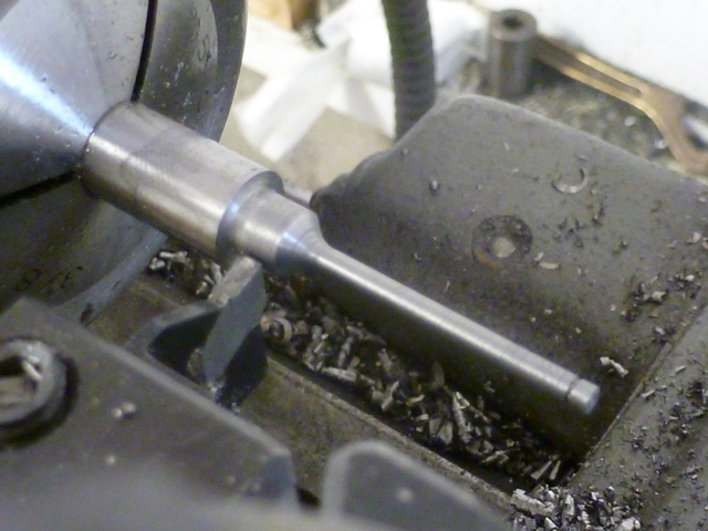
Getting the stock started into the jig is a little fiddly. The cutter is
withdrawn to get it out of the way. Once at this point, I pulled back the
cross slide just enough to feel a touch, trying to ensure that any radial
force would immediately meet resistance at the backside of the bore. I ensured
smooth operation all the way to the collet, and then slathered the stock to
the left of the jig with cutting oil. The article suggests drilling an oiling
cavity at the top, but I forgot to do that.

20.jpg


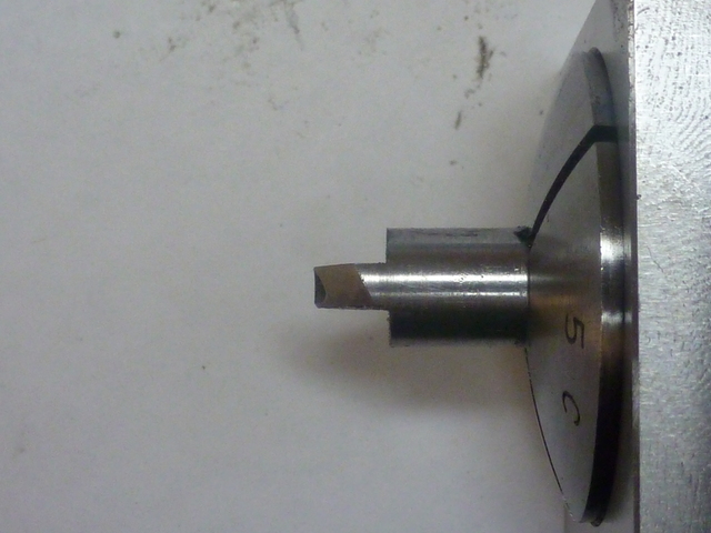
I advanced the cutter to touch the sized stem, and clamped it. Here you can
see the radius of the form tool. There is side and end relief, as well as
side -rake ground in, which is not obvious in this picture.

25.jpg


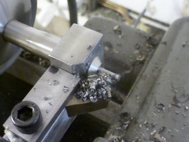
I cut with power carriage feed on the slowest gear, spindle speed somewhat
slower than I used with the sharp pointed tool. This is an action shot. There
is absolutely no chatter.

30.jpg


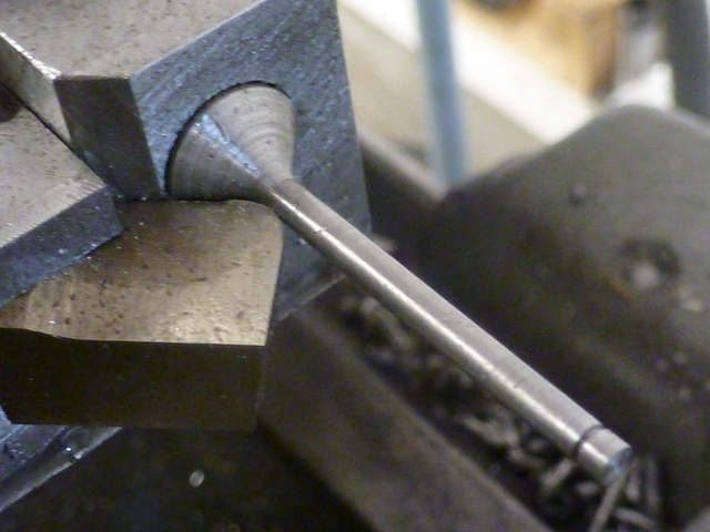
After stopping the feed, I pulled back from the work a little before turning
off the spindle (photo). Then I loosened the cutter and pulled it back some
to prevent scraping when I cranked the jig back.

35.jpg


I worked the stem and head underside with emery some (probably not enough),
then turned the head diameter and parted off.

40.jpg


I pulled the good old Taig into service for facing the top of the head.

45.jpg


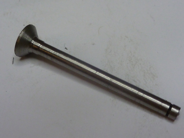
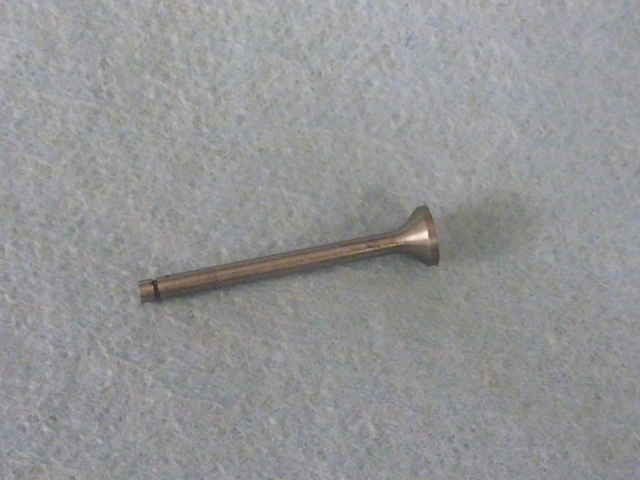
Here it is. Not as pretty as the one I just saw in Vince's Kiwi build, but I
think this will work. Most importantly, this process seems quite repeatable,
and I feel that the next one I make can only be better. Forward progress
does wonders for my sanity.

50.jpg


Having done all this, I'm still pretty sure I could have eventually
gotten equal or better results using George's method, but I'm glad I tried
this. Comments and criticisms are welcome as usual.

Thanks for looking in,
--Tim
 
Comments and criticisms are welcome as usual.

I have to admit my first reaction to your tool was one of" What am I seeing? That looks strange and flimsy!' then I read on. I will say it is an unusual but creative approach to a problem. You learned something your tool worked and did the job. That is what this hobby is about. IMHO the first priority is safety. and having fun is important. if you get hurt the fun stops.
You made a successive pats or parts you did it safely and had fun doing it what more can you ask.
Tin
 
Hi Tim,
When something is posted by myself or one of the 'old timers' it's to give the new fellows an idea of where to start. It's not always easy to do exactly like we do so this is where the learning part comes in and it looks like you've done quite a nice job of it. The valves look good and should work just fine. Keep up the good work.
gbritnell
 
Nice one Tim

Another way of doing it.

When I did mine I also had maching marks on the stem, but I left the stem about 0.05mm oversize and sanded the stem down to size using the valve guide as a gauge.

Vince
 
Neat approach Tim. I am not sure i would have even considered such a large cut on a part like that, so I certainly learned something form this post.

My Upshur Farm Engine plans showed up this week. I hope to be following in your footsteps soon :)
 
Thanks for your comments Tin, George, Brian, Vince, and Brian.
Glad you are all watching. Everybody else, too.

Yes George, learning is what it's all about. The big take-away from the valve
experience has been that I am losing my fear of tool-grinding. A big step
in my opinion, to lose one's fear of something.

Some further work has convinced me that the next time I make valves, a jig will not be necessary, but making
this one and using it somehow helped bring the process into focus for me.

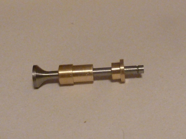
Today, I made valve guides and retainers out of brass. The work was so
straightforward I'm not going to describe it, except to show a little picture.

50.jpg


It seemed about time to make the valve seat cutter, and I approached it with
apprehension. I made it pretty much to Upshur's plan, but keeping in mind all
I had read from gbritnell on the subject, and also the counter-bore cutter
that Dave (steamer) showed recently in his Wallaby build.

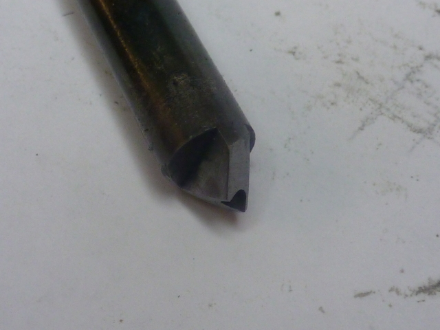
I used W-1 drill rod. Placed in a collet, I center-drilled and drilled for
a pilot. The pilot will be a #42 drill blank (the same size used to drill the
valve guide). I did not want to make the pilot integral with the cutter,
because this is to be my first successful tool steel hardening experience, and
I don't want the fear of a warped pilot to be part of it.

55.jpg


I used the valve jig I made previously to cut the cutter. The follower support
is not necessary, but this was easy to do and to get an angle matching the
valve.

60.jpg

65.jpg


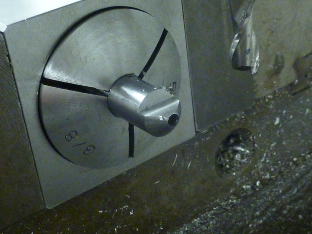
Into a collet block it went, and to the mill. I milled to form one side of
the flutes...

70.jpg


And then the other.

75.jpg


Then I had to file in the back-rake. I had to just jump in and start filing
before the geometry became clear in my head. I ended up making part of one,
and then a second more correct one. Here is a side-on shot of one of the
flutes showing how I brought the rake up the cutting edge. The collet block
was handy for holding the part under my magnifier lamp while filing.

80.jpg


Now the hardening. I've read it time and again; heat to bright cherry red and
plunge into water (W-1 rod, remember). I guess it was bright cherry red when
I plunged. I've also seen reference to cooked carrots... It was definitely
a uniform color, and I felt 'heated through' the entire cutting area.
I think it is George who suggested that since this is a hand tool with very
light duty, there is no reason to draw the hardness. So I called hardening
finished. I dressed the cutting edges some with a diamond lap.

85.jpg


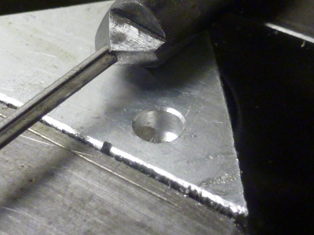
I stuck in a drill blank pilot and cut a seat in a test piece. It cuts,
and even under magnification, the finish looks pretty good. Still, I'll be
doing a little more work with finer diamond laps and I'll loctite the pilot in
before I go at my head with it.

90.jpg


Thanks again everybody for looking,
--Tim
 
One of the sets of gas engine plans I used to sell (sorry, I don't remember which one) showed a "cheating" way to make valves. Basically, first you drilled a ball into a bead, then silver soldered the bead to the stem stock, then mill the top half the bead flat.... and you have a valve.

 
Hi Allen, that is an interesting way to make a valve.

The valve guides I made previously were turned for a sliding fit in reamed
holes in the head. I admit my plan was to just loctite them in (the plans
say that would be alright). Then I was reading Vince's Kiwi log again, and I
saw where he had pressed his in.

Funny thing about reading some of the build logs here, you are prompted to try
and do better. So I remade a pair of valve guides for a slight interference
fit in the reamed holes (about a half a thou over), and came up with a little
doo-hickey like Vince did to ensure they would be pressed in straight.

I had gone out and got some #42 drill rods yesterday, one of which will be used as
the pilot in the valve seat cutter above. I used another to make a "toolmaker's reamer"
(with hat-tip to steamer. See
http://www.homemodelenginemachinist.com/index.php?topic=9854.0.)

That reamer was used to finish the holes in the valve guides, and a couple of
parts of the doo-hickey you see below.

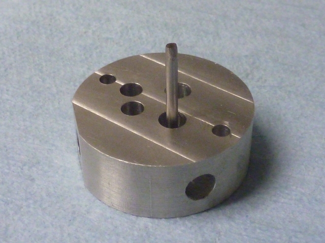
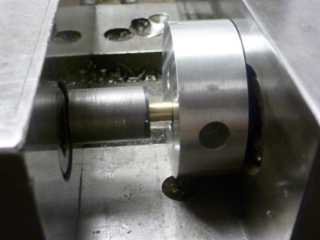
Here is a plug turned to closely fit the reamed guide holes in the head.
It is reamed to fit a length of the #42 drill rod.

95.jpg


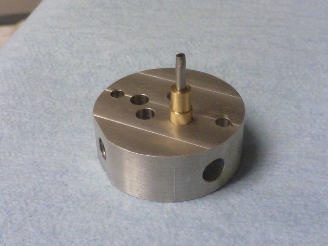
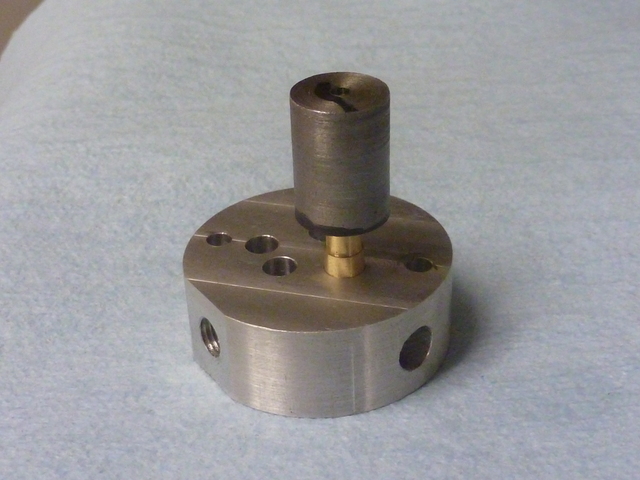
The following photo sequence shows the plug and rod in place in the head, then
the addition of the valve guide, then a "presser" piece which is also
reamed #42 and bears on the top of the valve guide.

100.jpg

105.jpg

110.jpg


The actual pressing took place in the mill vise. Here is the setup after
the first guide has been pressed in to depth. I did apply some 609 loctite to
the valve guide before pressing it in. I don't know if that does anything for
a press fit.

115.jpg


And here is the head with both valve guides installed.

120.jpg

Thanks,
--Tim
 
Looking very nice, Tim. On mine, I sanded the milling marks out of the head before installing the guides. Was a bit easier that way.
 
Trout squeezer,
Yeah, you're right. I realized that soon after I pressed them in. I just got caught up in the moment. Thanks for your attention!

--Tim
 
tvoght said:
I just got caught up in the moment

Now that's never happened to me ;)

It's looking good Tim. I am still happily following along.
 
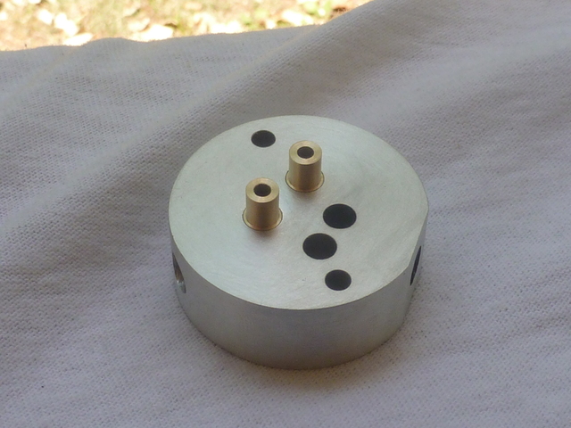
This picture is for Dennis. Milling marks gone.

125.jpg


And yes, getting to this point would have been much easier without the valve guides installed. I also addressed the gouges I put in the sides by clamping it unprotected in v-blocks. I hope I can pretty things up more when it's closer to finished. The sad fact is, I will probably never achieve the level
of polish most of the guys here do. I will justify it by saying my models are meant to be 'realistic' and represent the 'real world'...

--Tim
 
Tvoght---Don't worry---If your luck with valve cages is anything like mine you'll have those ones in and out half a dozen more times anyways. ;D ;D----Brian
 
Hello Tim,

Great job so far on your engine. I am following along with interest.

A little trick that you can use when trying to judge the color of steel when heating a small part or a cutting tool with a propane torch or similar for hardening, is to keep a magnet close by as you heat the part. The type with a telescoping rod with the magnet at the tip that is commonly used to fish-out small parts that are dropped works well. Carbon steel becomes non-magnetic at 1420 deg. F. This is near the transformation (critical) temperature that you are trying to achieve when judging the 'cherry red' color in plain carbon and low-alloy tool steels. The transformation temperature is the temperature that the tool steel must reach in order to become hard. In the case of W-1, this transformation temperature is also about 1420 deg. F. The magnet will help to take some of the guess work and interpretation out of trying to determine the color of the heated steel and lets you know that this point has been reached when it is no longer attracted to the steel. It is best to slowly and evenly raise the temperature to this point. Once the magnet is no longer attracted to the tool steel, make sure that the entire working surface of the tool is at this temperature or slightly above. Then quench immediately. Ideally, we would like the part to soak at the critical temperature for a period of time, but for small tools heated with a propane torch, it is too easy to overheat them.

This works perfectly for W-1, but many of the higher alloy tool steels have their transformation temperature above the point of becoming non-magnetic (for example A-2 which is about 1750 deg. F). It works well with O-1, as its transformation temperature is just slightly higher (1500 deg.F), so just soak it a bit longer. It is very important to not overheat the tool steel, especially with water hardening tool steels like W-1, as there is a good chance that cracks will develop if it is quenched from too high a temperature.

Try it next time. It should take away some of the worry about whether the tool steel will be hard after the quench.

Regards,
Mike
 
Back
Top