An Upshur Farm Engine (first I.C.)

Home Model Engine Machinist Forum

Help Support Home Model Engine Machinist Forum:

This site may earn a commission from merchant affiliate links, including eBay, Amazon, and others.
TroutSqueezer,
The .5 long bushings specified in the plans will still extend past the thicker plates, so I checked that.
Nevertheless, your point is well taken, and I am going to carefully evaluate how things stack up before I start the crank.

At this point, I have not given ignition sufficient thought, only that it will be Hall effect and I'll probably use Howell
components. I'll have to get a much better handle on that before starting the crank, and I may need to cut a pocket on
that side of the frame for sensor mounting. I can always do that later.

Thanks for watching!

--Tim
 
Tim, the plugs turned out very well and don't show at all in the pictures. Bead blasting may give it an even more uniform appearance too. When you begin to think about the ignition, you may want to check out S/S Machine at this link as well if you haven't already. I found their system easy to install and so far faultless in operation: http://www.cncengines.com/. No affiliation, just a satisfied customer. Will be following along with interest as you progress!!

Bill
 
I'm very interested in bead blasting because I think it would give me more of a cast appearance. Is that right? I need to investigate what kind of setup
I'd require to do it. If I bead blasted, how would I protect the machined surfaces that I don't want blasted?

Thanks for your input, b.lindsey

--Tim
 
Tim,
I have access to a benchtop unit like this: http://www.grainger.com/Grainger/ww...ch&Ntt=6ZA40&N=0&GlobalSearch=true&sst=subset which works well on smaller parts. Its slower and not as agressive as the larger industrial sized units which is probably good. As far as masking goes, I have used blue painters tape and it works quite well similar to what's shown below. Hope that helps.

Bill

Crankcase 013.jpg


Crankcase 014.jpg
 
That is indeed helpful Bill. All things considered, bead blasting may have to be considered outside the scope of this project.
You've got me thinking though.

By the way, your Briggs is magnificent. I haven't had a chance to read the build log yet, but I will.

--Tim
 
Tim, I am enjoying your build of one of Dick Upshur's engines. I only got to know Dick a few years before he passed away and only from talking to him at engine shows. I am sure he would be pleased with your version of his engine. He was a true gentleman and very helpful, at one time he was even offering material kits with his plans and he always sold out. Its nice to know his legacy lives on in his engines. I built 2 of his engines myself. The Upshurs are a good place to start in building an IC engine IMO. I can't wait to see how yours finishes up.

I also am a big user of C&Cengines electronic systems, no affiliation, just a happy customer. Dave
 
Thanks for writing Dave. I sure wish I'd had a chance to talk to Mr. Upshur.
Working from his hand drawn and lettered plans is a joy.

I want to encourage anyone who's considering their first I.C. engine
to get these plans and study them.

Dick made every effort to make these engines as easy as possible for
the rank beginner. By offering clear options in several places, he lets the
builder play to their strengths and adapt to the tools available.
These plans instill confidence in the first-time builder.

Some here have said that no two Upshur farm engines are built alike,
and I think that's because the options offered puts the builder in the
mindset that he can be flexible. For me, these engines are a perfect
platform for skill-building. Right now, I'm interested in trying
techniques in scratch-build fabrication, so on the frame and cylinder
I'm taking the extra time and effort to try some things. Elsewhere,
I can stick much closer to the book.

I'm enjoying myself, and I hope builders will be enjoying these plans
for a long time to come.

--Tim
 
I just caught up with your build Tim, and am looking forward to the rest. This engine is on my short list for my first IC engine so I am excited to see your build log.

I like what you did with the frame. It will finish out to look much more like a casting.

I am over here in Terre Haute. If you want, PM me your address, and I'll send you a piece of aluminum that is bead blasted so you can see what the finish would look like.
 
Thanks Brian, I've been watching your PM Research #1 build. I PM'd you.

--TIm
 
I decided to get some of the (how do you say it?) 'fiddly bits' taken care of.
The rocker arm is made from some 5/16 thick 303 stainless I have on hand.
I sawed out a piece long enough to clamp on the ends. I put it in the mill
vise and cleaned up one side.

5.jpg


Then I clamped it down to a sacrificial plate I still had clamped to my
mill table. I thinned it down between the clamps to .125. Actually, several
thousandths thinner as it turned out, but I'm happy.

10.jpg


Then I cut it to width (.25) by side milling. In this process, the DRO is
zeroed with reference to the first edge after I cut it. The DRO was zeroed
in the X axis to roughly the center of the section I've worked down.

15.jpg


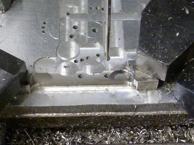
Two semi-circular features are added with the .5 inch end mill by side-milling.
All the numbers for the DRO were worked out quickly in CAD before hand.

20.jpg


The pivot hole and hole for the push-rod clevis pin are drilled and reamed.
The plans simply have 2-56 screws in these places, but I plan to make up some
little brass shoulder screws for these places. You may ignore what seems to
be a place where I milled a little deep on the right end.

25.jpg


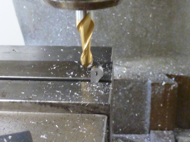
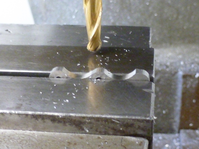
While I could have hung this end off the vise jaws on a drill bit and faceted
it for rounding, I'm taking this opportunity to come up to speed on using a
step-off chart for this kind of thing. Here I've stepped off the rounded end.
I may have over done it on the number of steps, but this was kind of fun,
and I'm satisfied with the results.

30.jpg


The other end really called for a step-off chart because there is no through
hole for reference. I rounded off that end, and then thinking on my feet,
decided to use a few middle values off the chart to step out the feature
around the pivot hole. I kind of eye-balled the position before cinching the
vise. Later it occurred to me that I might have done the same
thing for the transition between the large and small radii at the ends. At
this point though, I'm feeling a little lucky with my 'eye-ball' technique,
and that transition is left to filing.

35.jpg


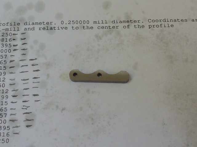
Here is the part before it has been touched by emery or file. It's laying on
the chart I used.

40.jpg


Thanks for your attention,
--Tim
 
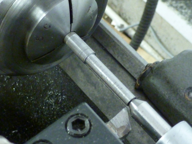
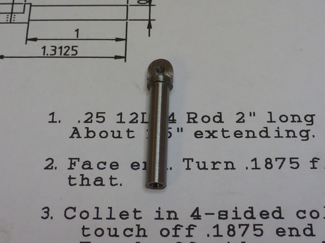
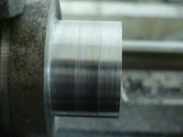
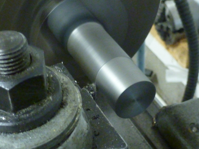
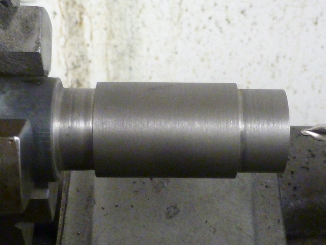
Next up is the rocker arm post, which I made from 12L14 steel.
I put a length of 1/4" round in a collet in my lathe and turned
the shaft diameter and just cleaned up the portion beyond that.

45.jpg


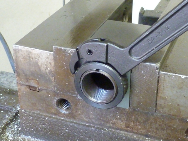
I then put the collet in a square collet block. This picture shows
what I learned about using these collet blocks. To tighten that ring,
you need a pin spanner something like this. I should have made one to
save money, but this is the one I bought, and it's a wonderful thing.

50.jpg


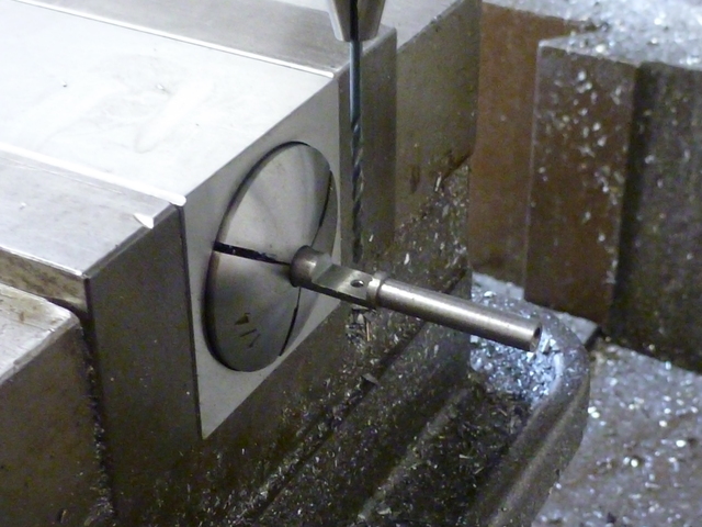
With the collet block in the mill vise, I milled off the flat
portion where the rocker arm will pivot and drilled and tapped
for a 2-56 screw.

55.jpg


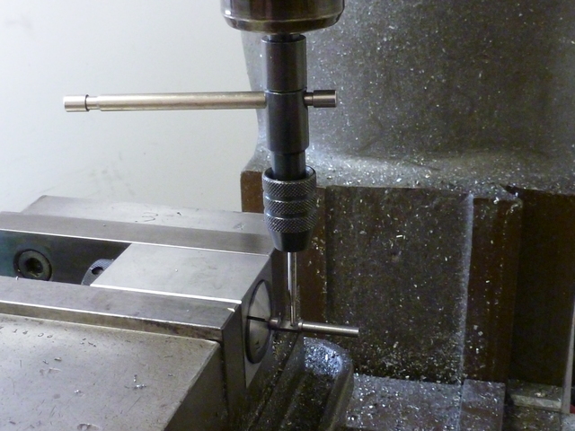
This picture shows a tool I really like. A tap wrench with a pilot
which is held in a drill chuck or 1/2" collet. Another wonderful
thing.

60.jpg


All that rounding I did on the rocker arm with the step-off charts
was on radii of .125. The top portion of this post is .25 wide as
well, so I once again made use of the step-off chart I'd generated
for the rocker arm. Here's the part right off the mill. Another thing
I wanted to mention is that for all but the simplest parts, I take
an enumerated set of step-by-step operations with me to the shop.
I've seen this recommended by Bogstandard a few times, and I
absolutely agree with him. Without it, I could not do this, even in
the crude way that I do.

65.jpg


Where did you get that pin spanner, I have the same setup and need one of them. My collet block kit also came with a hexagonal block also which is handy. Rocker post looks good.

Brock
 
Brock,
I got the spanner from McMaster-Carr, and it cost nearly as much as the block set. Yeah, my set came with a hexagonal block too, as well as a cam-lock type of drawbar which doesn't work very well and gets in the way. The rings work great if you have a way of tightening them properly.

--Tim
 
Looks like I am gonna be making one. Cheers
Brock
 
I made a cylinder sleeve tonight out of cast iron (durabar).
I began by making a plug gauge with progressive diameters of .748,
.749, and .750. Here is a closeup.

5.jpg


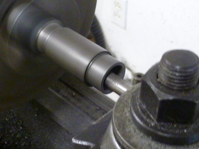
The durabar comes oversize. The nominal 1" stock came in at about 1.1.
I started by turning it down to 1". Action shot!

10.jpg


The ends were then turned down to .875. I still haven't learned the good
and right way to turn a part like that to the left; between the chuck and
a right shoulder. I struggled with various tools, trying to match cutting
depths and to get the length to the shoulder right. The results are useable,
but I wish I knew how to do this.

15.jpg


I drilled 11/16" and then began boring. I had been dreading this. I don't like boring.
Using a telescopic bore gauge, I brought it to .748, and then checked it with my
plug gauge. Pretty close. The .749 step of the gauge went through, but not the
.750. I took one more boring pass at the same setting. After that, the .750 step
passed. After cutting off, I checked the other end, and the .750 step passed there
too. The feel suggests there may be a couple of tenths of taper from end to
end.


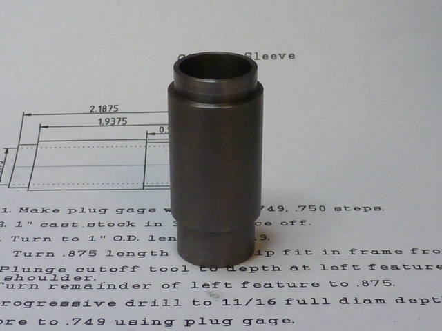
20.jpg


Here it is after cutoff.

25.jpg


Thanks for looking.

--Tim

Edit: Whoops! linked wrong pictures. This should fix it.
 
Looking good Tim...are you backing the tool out before you stop on that inboard diameter....that might help.

Dave
 
Hi Tim,
It looks like you're making good progress. If I could make a small suggestion that might help in the future. When turning a cylinder do your boring first that way you'll have extra stock on the outside to help dampen the internal cut. It will help prevent chatter. Then cut the outside. It also depends on the type of material you're cutting.
gbritnell
 
Hi Tim, The cylinder Sleeve looks good to me and the few tenths taper you mention should hone out nicely. Its nice to see the progress on this one, keep up the very nice work!!

Bill
 
Dave, George, and Bill,
Thanks all for your comments and suggestions. I really appreciate it, and that's why I'm "baring my soul" here. To get help from guys of your caliber.

--Tim
 
The Upshur plans suggest two possible ways of making a built-up cylinder
for the horizontal water-cooled version of the farm engine. I chose one
which uses a common hardware store item; a 'tailpiece' for a
lavatory drain. It's a piece of thin-walled brass tube (chromed, in this case).
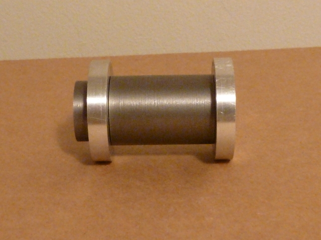
I first had two turn two aluminum rings to slip over the turned-down ends
of the cylinder sleeve. I don't have pictures of the process, but I chucked
a 1.5" piece of 6061 rod and drilled and bored it for a slip fit over the
sleeve ends, turned the outside to slip into the brass tube, then
parted off the rings. Here are the rings slipped onto the sleeve. They
will later be loctited.

30.jpg


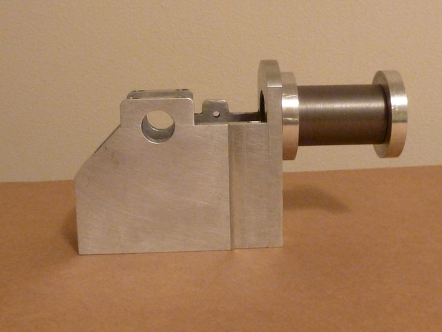
Here you can see how the sleeve slips into the hole bored in the frame
front.

35.jpg


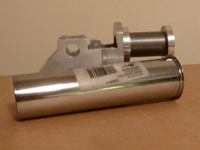
And finally, here is the tube I got at the big home improvement store.
I chose this method of building up the cylinder because it seemed
simple, but I had been dismissing the difficulty of cutting the thin-walled tubing
to length (I've already ruined one trying). Does anybody have any ideas? The
best idea I've got right now is to put the tube on a sort of expanding mandrel
made of wood, and cut it off with a cutoff tool in the lathe. The cutoff doesn't
have to be perfect I guess, because I can face it off smooth after it is JB welded
to the rings (which will be loctited to the sleeve). Still, I don't want to distort the
tube in the process.

40.jpg


Thanks for watching my build!

--Tim
 
Back
Top