An Upshur Farm Engine (first I.C.)

Home Model Engine Machinist Forum

Help Support Home Model Engine Machinist Forum:

This site may earn a commission from merchant affiliate links, including eBay, Amazon, and others.
Hello Tim,
Very nice build. I agree with George and his suggestion about doing the bore first then finishing the OD. I have made several Upshur engines, and my method is to cut the legnth of cylinder stock slightly longer than required. Center in a 4 jaw chuck, center drill, drill through to.500, then bore to.748 or there abouts. I then hone the cylinder to a finish from both ends to ensure both ends are parallel, and after it is finished I make my piston to fit. I made up a wooden mandrel from seasoned Maple several years ago that is about .748 OD and 6 inches long, and if the cylinder is not a tight press fit I slightly wet the mandrel to expand it and press on the cylinder. It holds very tight , and has the added benefit that it will not score the cylinder . Then mount the mandrel between centers and finish the OD reversing it for the shoulders. To remove the mandrel I put the whole thing in our freezer to cool overnight, and the wood mandrel falls right out. This method works well for thin wall material such as the tubing, also. I do all my cylinders, even for the steam engines made from brass, this way. Good luck, ART
 
Note that the following work was done before reading the very helpful
suggestions from Art above. Thanks Art. There's always a next time.


I wanted to get that thin-walled tube cut and out of the way tonight, so
I proceeded with a variation of the wood mandrel plan I outlined before.
If it's possible to hurt a metal lathe's pride, I did my best here. I
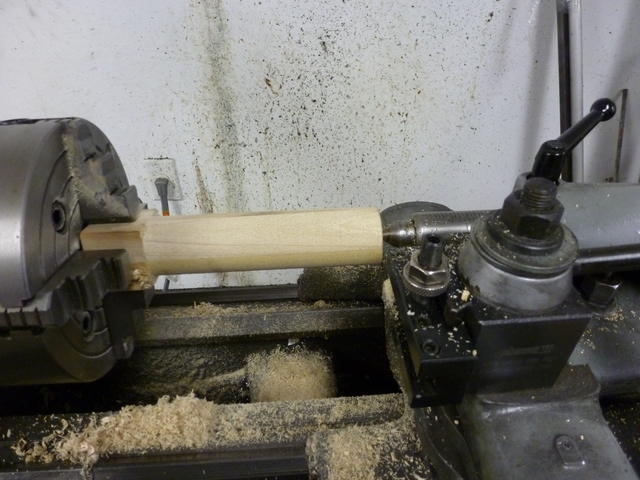
chucked up a piece of hardwood and turned it down for a slip fit inside
the tube. I'm sure many are offended.

45.jpg


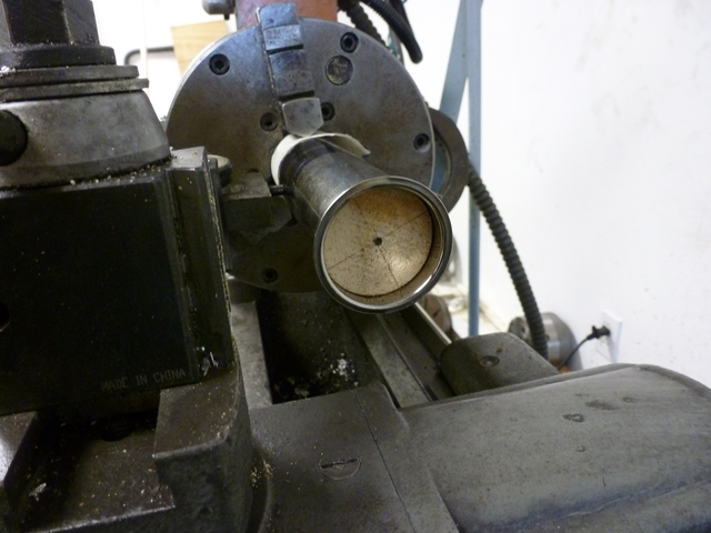
I sawed off the round chunk and slipped it inside the tube for support,
then chucked the tube. On this first try, I tried protecting the tube with
paper and not tightening the jaws much. I was going to cut gently.
Purists please note I have already mostly cleaned up the sawdust.

50.jpg


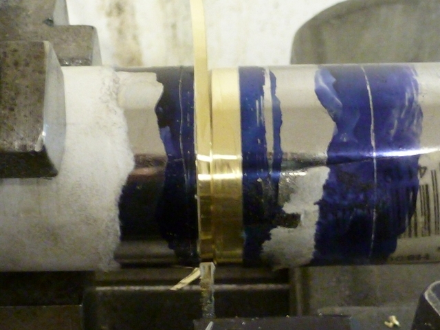
The cutoff results were a little strange. As I advanced the cutoff tool, a
brass band occurred to the right of the cut, as if the silvery coating was
stripping off over there. I cut through and discovered my cutoff portion was
too short. There is in fact a step detectable with the fingernail between
the brass portion and the silvery part.

55.jpg


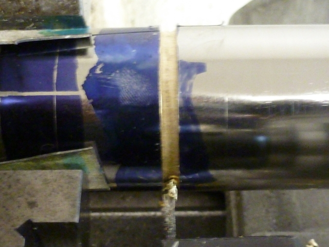
I tried again, this time using pieces of aluminum Indiana license plate
at the vise jaws to protect the tube. I tightened down good. This time
I got a good cut at the correct length.

60.jpg


Trial fit.

65.jpg


The water hopper, which Upshur assures us is a purely decorative feature,
comes next.

Until then,
--Tim
 
This weekend I got to a part I had been looking forward to. The water
hopper. This is pure style, and the part that will give the engine its
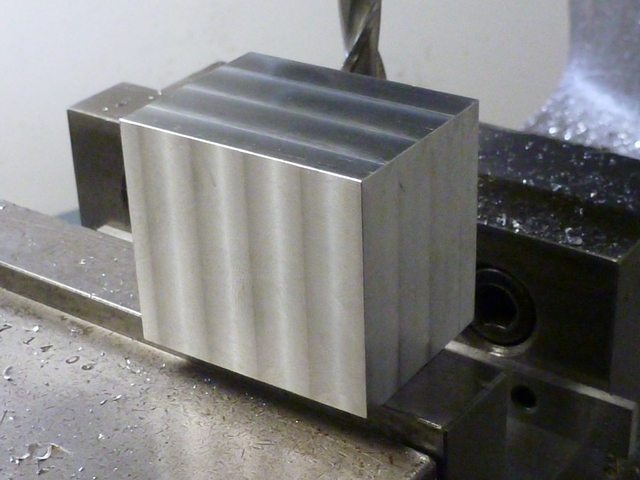
personality. I started by chopping off a hunk of 6061 on my newly-
acquired import bandsaw. I squared it up in a series of milling vise
operations.

70.jpg


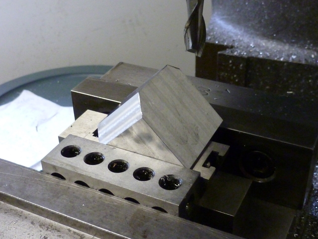
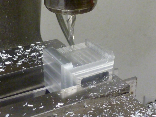
The next step was to setup an angle block at 45 degrees and bevel the
upper four edges.

75.jpg


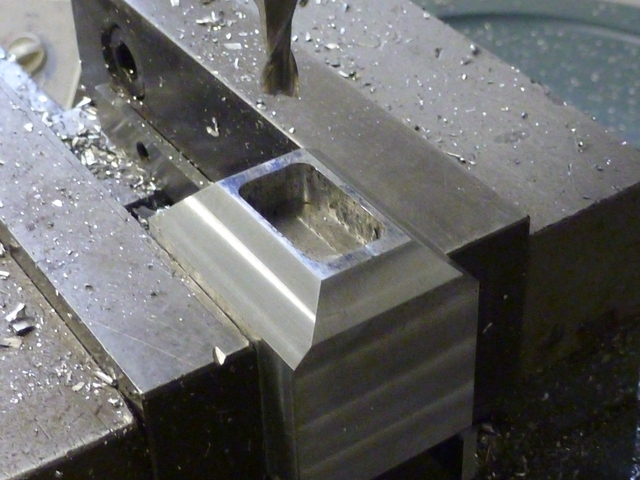
Then I milled out the hole at the top. I'll be milling a cavity from the
bottom to meet up.

80.jpg


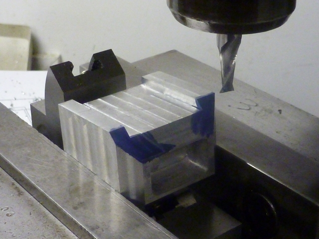
I cut an inset portion on each side. This is not only decorative, but will
provide a clamping surface for later operations.

85.jpg


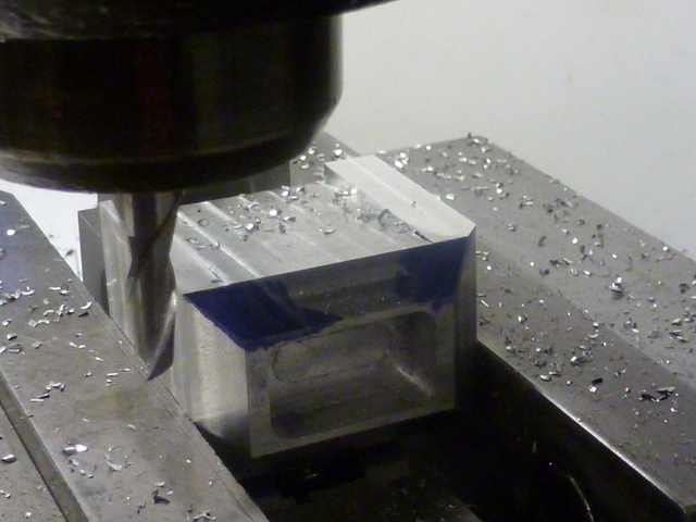
Then I set up the angle block for a 5 degree incline and milled the sides.
I'll mill until I reach the point where the inset portion meets the upper bevel.

90.jpg


Like that. I milled the front back at 5 degrees, too.

95.jpg


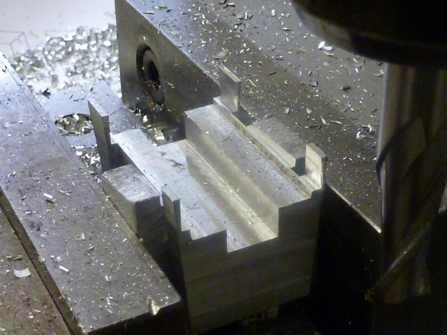
I clamped the part upside down in the vise. You can see here where I clamp
at the insets. I'm using accurate aluminum tooling plate as clamping parallels.
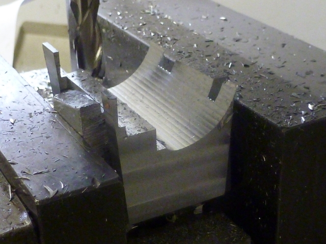
I'm preparing to mill out the semi-circular tunnel that will seat on the
cylinder tube. Using an end mill that has seen better days, I chop out a
goodly portion in preparation for stepping out the curve with a ball end
mill.

100.jpg


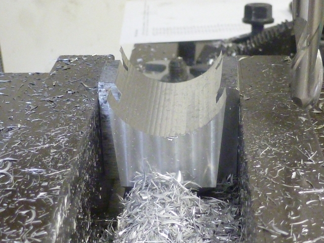
The step-off procedure proceeds.

105.jpg


That's done. Of course a CNC machine would be nice, but I wonder if it
could be as satisfying as this.

110.jpg


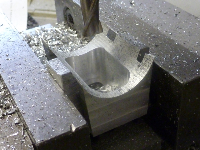
Finally, I hollow out the water cavity to meet up with the top hole I cut
out earlier.

115.jpg


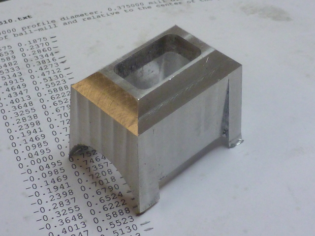
All machine operations complete.

120.jpg


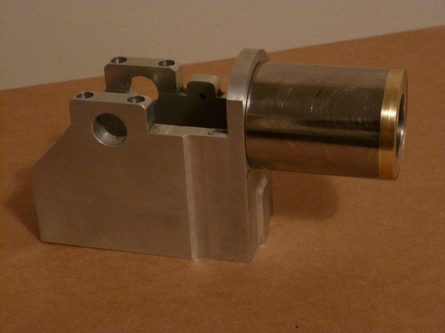
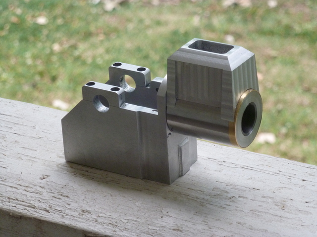
Getting the idea. I want to slightly radius the hopper edges by filing, I
hope I don't ruin it in the process.

125.jpg


Thanks for viewing,
--Tim
 
Very nice Tim. :bow:

Which software programme are you using for that step off procedure?

Thanks

Vince
 
Hi Tim

Great progress on your engine; I have used the step and cut method many times in the past for convex radii but never for concave; may have to give that a try sometime.
I have a little book that I purchased form Guy Lautard some years ago that is big help doing this kind of work.

Keep up the great work!

Dave
 
Thanks Vince, Dave, and Dave for your kind comments.

Vince, The step charts are generated with a program I wrote in the Python programming language.

--Tim
 
Wow! I'm getting the idea that perhaps you have more experience than you let on. This looks like the work of someone who has been at it awhile. Great job.

-Trout
 
Looking good Tim! :)
 
Thanks for your comments Trout and Brian.

The rings that were previously made to go on the ends of the cylinder
sleeve were not quite complete. They needed holes drilled to pass the studs
which extend from the front plate of the frame, through the cylinder and
cylinder head. The holes need to be pretty accurately located, as they will
be drilled for a close fit on the studs. In fact, the plans call for a #29
drill, which is .002 smaller than the diameter of a 6-32 screw. I'll be
drilling a #28, which is .002 larger.

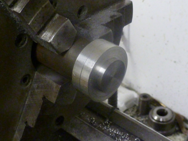
I turned a locating plug of 12L14 steel for a slip fit in the bore of the rings. Since
the turnings on the end of the cylinder sleeve turned out somewhat different
diameters (.874 and .867), I had bored the rings to fit their respective
ends, and here I turned two steps on the plug to fit each ring. Here's the
plug before cutoff with the rings slipped onto it, The larger bore first,
then the smaller.

130.jpg


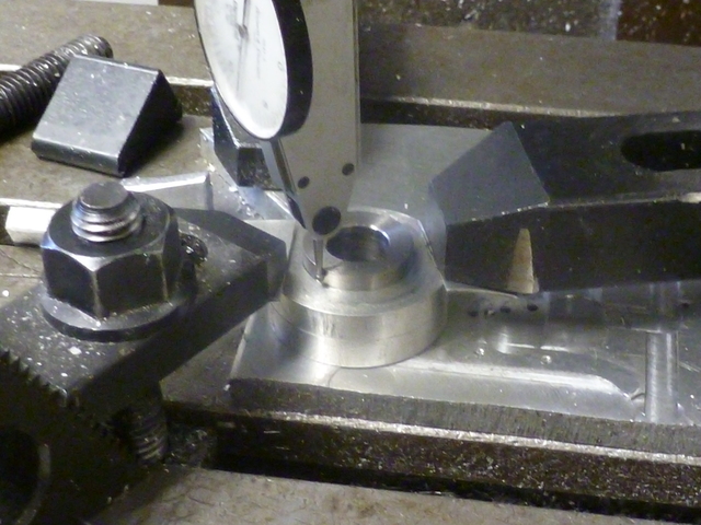
I drilled out the center of the plug to make cutoff easier, and to relieve
the center so that when I placed it on my mill bed, the contact would be
around the outer edge. I clamped at the ring's edge onto the tooling plate I
still had clamped to the table. I first roughly centered the spindle on the
plug with a drill bit through the hole, then centered as close as I could with
an indicator.

135.jpg


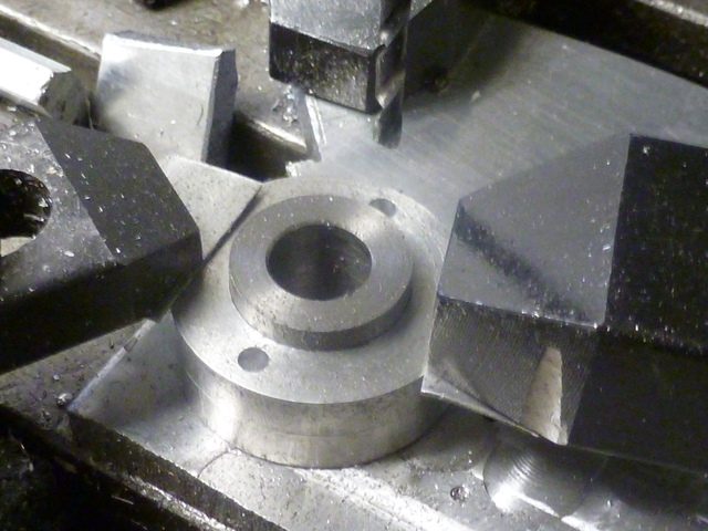
It was then a simple matter of locating the holes with the DRO, center-
drilling and drilling through and into the sacrificial plate.

140.jpg


Please excuse the quality of the photos.

Thanks everybody who's watching,
--Tim
 
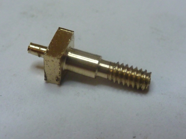
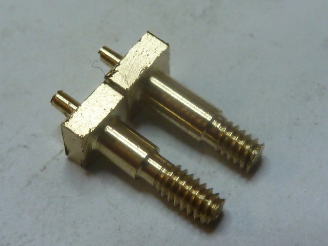
At certain pivot points in the design, the plans call for just a 2-56 screw
through a free fit hole. I mentioned that when I made the rocker arm
and rocker post. I said that I was reaming the rocker arm 3/32 and that I would
make a shoulder screw as a pivot. Here's what I did.

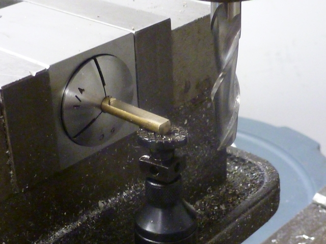
Starting with quarter-inch brass rod in a square collet block, I milled four
sides for a 5/32 square head. I'm doing enough length here for two screws I'll
need and then some.

70.jpg


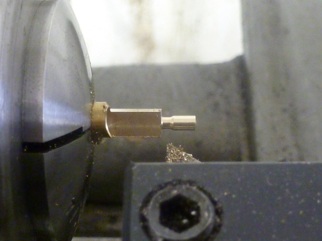
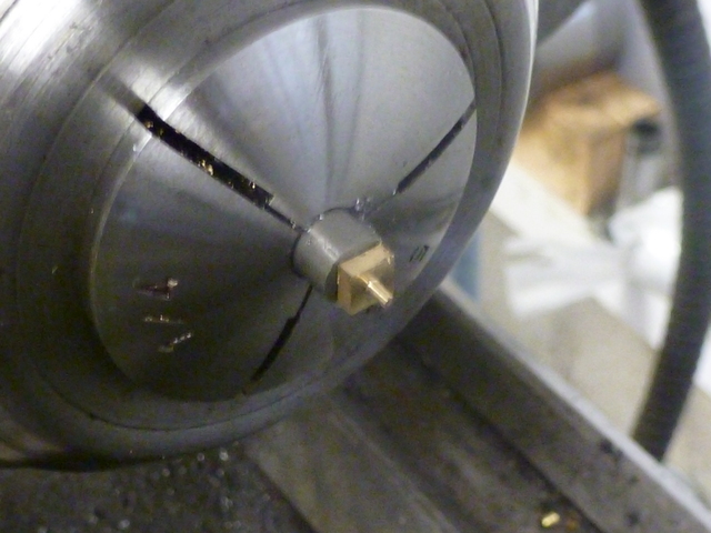
With the collet in the lathe, I turned to diameter for a 2-56 thread. I
haphazardly provided some relief at the shoulder. Length and depth were by-
gosh-and-by-golly.

75.jpg


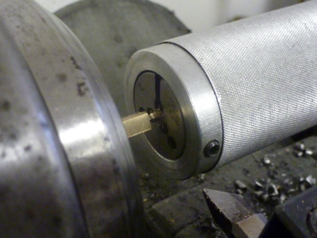
I threaded it using a piloted die holder held in the tailstock.

80.jpg


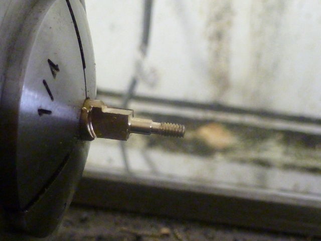
Then I cut the shoulder to .093. Looks like I've got more than enough
relief.

85.jpg


I parted off and got this. A pretty big nub to remove, but not bad, I
think.

90.jpg


I needed another (to different length specifications) for the rocker arm
clevis.

95.jpg


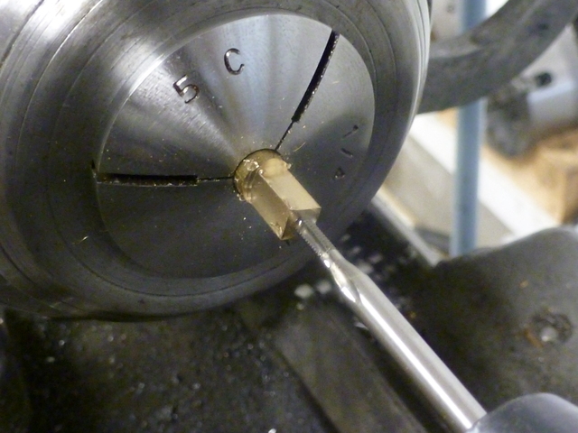
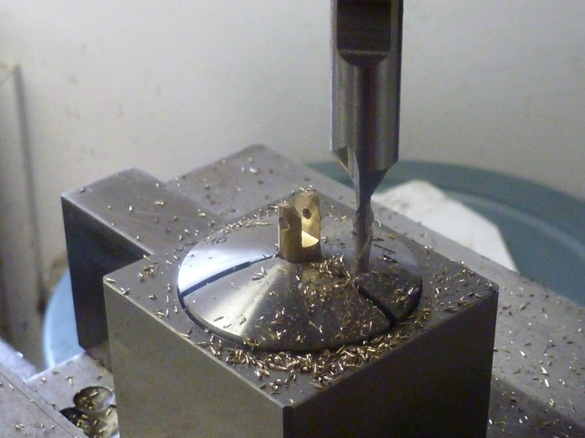
I still had enough square leftover to make a couple of nuts. I drilled and
tapped the length of the squared portion.

100.jpg


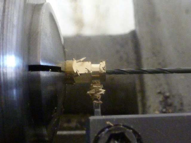
Then cutoff two. I slipped a small drill bit in there to catch them.

105.jpg


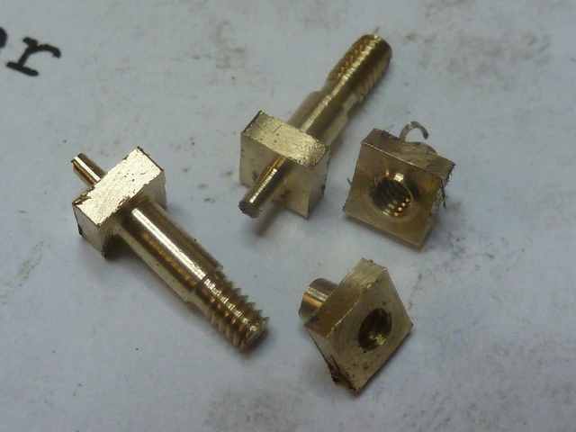
Tonight's results, badly in need of all-around cleanup.

110.jpg


Thanks everyone!
--Tim
 
Keeping this log is a great help to me, because a natural part of
my personality is that I respond to accountability. The knowledge that people
are watching is helping me stay on the case. I'm trying to keep this log going
so I don't lose momentum. I am concerned that my level of detail is a little
agonizing, and surely most here don't need such detailed explanations of how
a relative neophyte works. Still, I am hoping that by showing how I'm doing
things, those more experienced may point out better ways.

To clean up the parting nubs that were left on the screws I made previously,
I put a short piece of steel in a collet and drilled it for a 2-56 thread,
then drilled and reamed for the shoulder portion of the screw, then
threaded the bottom of the hole. I was then able to clean up the screws in
the little fixture.

115.jpg


I made up the clevis from a piece of quarter inch brass round. I did all
of the work in a collet, both in a 4-sided block and in the lathe. I do not
regret my recent purchase of the collet blocks. Here I have rounded off the
end of the clevis (using the step and cut method), and have cut the slot for
the rocker arm. I'm leaving out most of the details, because it's all stuff
I've done before in this log.

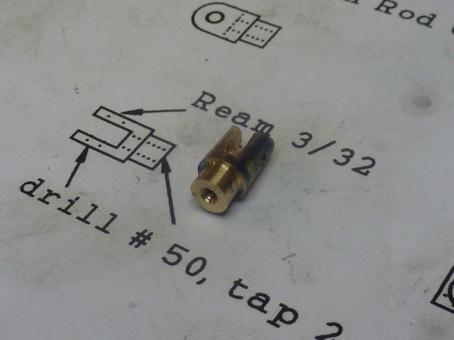
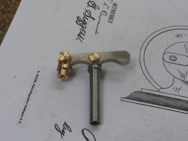
120.jpg


Finished after turning down a shoulder and drilling and tapping for the
push-rod.

125.jpg


A trial fit of rocker arm, rocker arm post, and clevis. I'm not really
happy with the scale of the hardware. I may eventually want to re-make the
screws and nuts with smaller heads.

130.jpg


Thanks for watching my efforts.
--Tim
 
Keep up the good work Tim. I'll expect another installment in a day or two! (Just tryin' to help with the accountability thing :) )

I understand what you mean about feeling like you are including too much detail. On my PMR#1 log, I find myself asking "Do they really want to see another picture of a drill bit in a chuck poised next to a hole?" However, when I read these posts, I enjoy seeing the pictures no matter how basic. I guess my vote is for more detail :)
 
From one neophyte to another, keep up the detail, Tim!

Maybe the more experienced of the group don't really need to see that picture of a drill going into a hole, but us young whipper snappers might see something in the setup or procedure that wasn't so obvious to us before. I learn a little bit from every post I read, and I can't learn enough!

- Ryan
 
Yes please Tim, no harm in the details.

Vince
 
Tim,

You just can't put too much detail into a post, like I have found over the years. Not everyone is the same, and of course we have a lot of beginners on here, and you are teaching them as well.

If you show everything, and it is narrated correctly, so that it can be understood by everyone, then less questions need to be answered and so makes a more interesting and compact post, it also helps to prevent change of direction or hijacking.

You are doing great on this post, just right, so keep it up. :bow: :bow:


John
 
I think the level of detail in your log is just fine. Keep up the good work. I've been on this forum for a long time and I can't remember any instance of anyone complaining about too much information in a post.

Another way a detailed log helps the novices (and others) is to show them the sequencing of operations, often one of the most difficult factors for newcomers to get their minds around.
 

Nice job nice writeup


When parting off bevel the tool so the right side (part side) is longer that way whatever nib you get tends to stay on the parent stock and is easer to remove. Also I learned in basic machining school to debur the part while it is still in the lathe. the front side it is easy. the back side is also easy just start the parting operation so you have all sides of the nut or bolt exposed . retract the parting tool stop the lathe clean up edges with a file then procede. I think you will find this quicker and easier than deburing small parts by hand.
Also make a bench pin if you do not have one. this will aid when and if you forget to debur on the lathe.

If you need an explanation of a bench pin just say so i will do a write up on them.

Tin


110.jpg


Tin
 
Brian, you have an open invitation to prod me whenever you feel like it!

Ryan, I'm like you. I never fail to learn something by reading here.

Vince, Thanks for your encouragement. I feel better now.

John, if you say I'm doing alright, that's enough for me. I learn a great
deal from your posts.

Marv, you've got me thinking about procedure in this hobby, and how that
relates to my profession (software). I write complex sequences of operations
every day. Surprisingly, I've never thought that much about how that drives my
need to work out and document procedures before going into the shop. I know
that is something that John advocates, too. Maybe I can find a way to make
that more explicit in my posts (you may have noticed how sometimes my
photographed parts are posed over oiled-up procedure sheets).

Tin, thanks for the hints on parting off and deburring. Getting better at this
is -for me- a matter of learning basic skills like those you point out. I've
never heard of a bench pin, and I bet a lot of others haven't either. I
would appreciate a write up!

--Tim
 
Back
Top