You are using an out of date browser. It may not display this or other websites correctly.
You should upgrade or use an alternative browser.
You should upgrade or use an alternative browser.
A vertical single 4-stroke IC engine
- Thread starter cfellows
- Start date

Help Support Home Model Engine Machinist Forum:
This site may earn a commission from merchant affiliate
links, including eBay, Amazon, and others.
Good video Chuck. Every time I build and i.c. engine and have trouble with it flooding like crazy, I think I should be trying propane.--Brian
- Joined
- May 27, 2010
- Messages
- 2,999
- Reaction score
- 1,171
Here is yet another video as I continue looking for ways to improve carburetion for my engines. Here I've got a quick and dirty set up to run propane.
http://www.youtube.com/watch?v=EbhF-mVQGO0
Even with this crude set up it seems to be running better than anything I've achieved with liquid fuel. Next I guess I'll start on a demand valve for it and maybe work on improving the mixer.
Chuck
I like the idling speed,she thumps away like the old WW2 Matchless. You hear every firing stroke and exhaust stroke. Almost like the Ruston single cylinder
engine running in the Heat Engine Lab,Singapore Polytechnic.
- Joined
- Aug 25, 2007
- Messages
- 3,890
- Reaction score
- 715
I like the idling speed,she thumps away like the old WW2 Matchless. You hear every firing stroke and exhaust stroke. Almost like the Ruston single cylinder
engine running in the Heat Engine Lab,Singapore Polytechnic.
Thanks Brian, Phil. Thanks, Gus, and your right, it does sound a bit like the old Matchless Singles.
Here is still another video. In this video, I'm using a commercial carburetor. I don't know the manufacturer, but it has a venturi of about .21". It has separate high speed and idle needle valves. There is no air bleed, but the upper needle valve closes off the fuel as the throttle closes.
[ame]http://www.youtube.com/watch?v=JQ6MHgUQJeY[/ame]
The engine still doesn't idle quite like I want it to, but it's close. I do plan to continue experimenting with propane and butane just to see what's possible. Sorry for all the videos... hope you all aren't getting bored with them!
Chuck
Philjoe5
Well-Known Member
- Joined
- Jul 12, 2007
- Messages
- 1,727
- Reaction score
- 321
- Joined
- Aug 25, 2007
- Messages
- 3,890
- Reaction score
- 715
One thing I've learned from the folks on this forum is that looks and attention to detail are important since many of our models will spend most of their time on a shelf being looked at. And I'm usually one of the worst about getting it running then getting lazy about making it purty!
So, with that in mind, I spent today working on (functional) aesthetics. I had previously cut out a rectangular section on top of the wooden base to hold a small battery box. Since I've decided to run it on spark ignition from a common ignition box, the battery was no longer in play. So, I made a terminal strip out of plastic to fill the void and hold the connectors for the hot lead to the points and the ground wire.
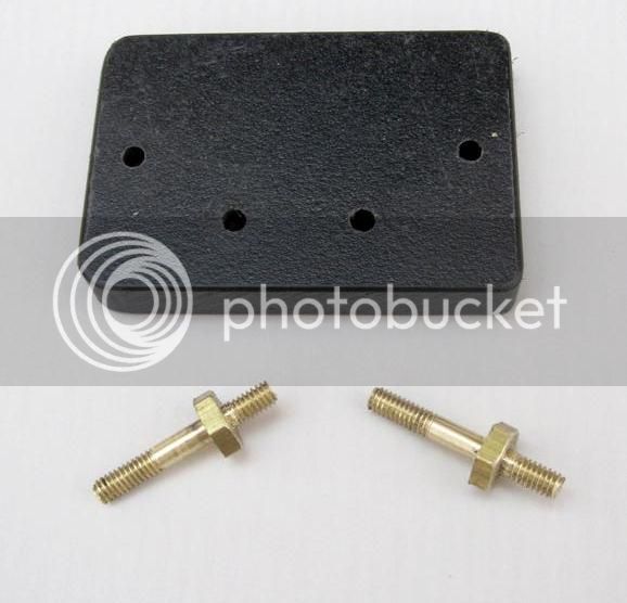
I also made the brass terminals from 3/8" hex rod.
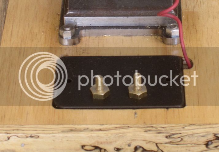
And I made the knurled nuts from 3/8" round rod. Here it is with all the engine wiring connected and ready to go.
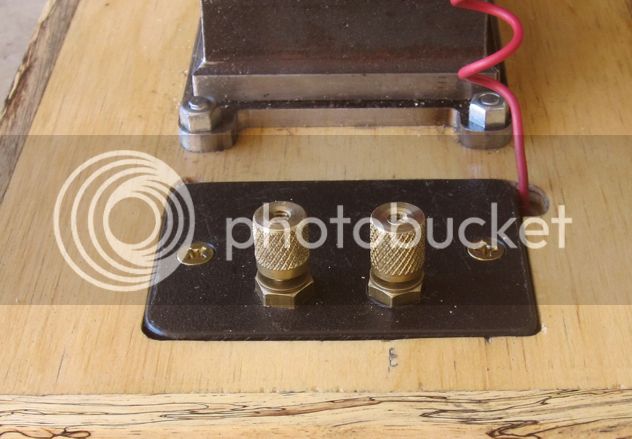
Next I'm working on completing the ignition box which will contain a 9v NICAD battery, a motorcycle coil, a condenser, and a switch.
Chuck
So, with that in mind, I spent today working on (functional) aesthetics. I had previously cut out a rectangular section on top of the wooden base to hold a small battery box. Since I've decided to run it on spark ignition from a common ignition box, the battery was no longer in play. So, I made a terminal strip out of plastic to fill the void and hold the connectors for the hot lead to the points and the ground wire.

I also made the brass terminals from 3/8" hex rod.

And I made the knurled nuts from 3/8" round rod. Here it is with all the engine wiring connected and ready to go.

Next I'm working on completing the ignition box which will contain a 9v NICAD battery, a motorcycle coil, a condenser, and a switch.
Chuck

$39.99
$49.99
Sunnytech Low Temperature Stirling Engine Motor Steam Heat Education Model Toy Kit For mechanical skills (LT001)
stirlingtechonline

$45.99
Sunnytech Mini Hot Air Stirling Engine Motor Model Educational Toy Kits Electricity HA001
stirlingtechonline

$89.99
Outdoor Wood Boiler Water Treatment Rust Inhibitor- AmTech 300 & Test Kit
Alternative Heating & Supplies

$39.58
$49.99
Becker CAD 12 3D - professional CAD software for 2D + 3D design and modelling - for 3 PCs - 100% compatible with AutoCAD
momox Shop
![DreamPlan Home Design and Landscaping Software Free for Windows [PC Download]](https://m.media-amazon.com/images/I/51kvZH2dVLL._SL500_.jpg)
$0.00
DreamPlan Home Design and Landscaping Software Free for Windows [PC Download]
Amazon.com Services LLC

$25.34
$34.99
Bowl Sander Tool Kit w/Dual Bearing Head & Hardwood Handle | 42PC Wood Sander Set | 2" Hook & Loop Sanding Disc Sandpaper Assortment | 1/4" Mandrel Bowl Sander for Woodturning | Wood Lathe Tools
Peachtree Woodworking Supply Inc

$29.95
Competition Engine Building: Advanced Engine Design and Assembly Techniques (Pro Series)
Amazon.com Services LLC

$99.99
AHS Outdoor Wood Boiler Yearly Maintenance Kit with Water Treatment - ProTech 300 & Test Kit
Alternative Heating & Supplies

$519.19
$699.00
FoxAlien Masuter Pro CNC Router Machine, Upgraded 3-Axis Engraving All-Metal Milling Machine for Wood Acrylic MDF Nylon Carving Cutting
FoxAlien Official

$94.99
$109.99
AHS Woodmaster 4400 Maintenance Kit for Outdoor Wood Boiler Treatment
Alternative Heating & Supplies
barnesrickw
Well-Known Member
- Joined
- Sep 8, 2012
- Messages
- 645
- Reaction score
- 121
I'm not much of a make it pretty guy either. Wish I was, but it's just not me.
Sent from my iPad using Model Engines
Sent from my iPad using Model Engines
- Joined
- Aug 25, 2007
- Messages
- 3,890
- Reaction score
- 715
I'm temporarily back to working on the Vertical Single 4 stroke engine. Terry Mayhew, who is building the 18 cylinder radial engine, convinced me to give the hall sensor another try since he has had real good luck with them. So, I built a test circuit, also designed by Terry and published in his 18 cylinder build thread. Here is a short video describing the test circuit and showing it with the engine...
https://www.youtube.com/watch?v=oVHlDp2VKFE
I made a few substitutions to Terry's circuit. Instead of a 2N2222 NPN transistor, I used a 2N3904 that I had on hand. It won't carry near as much current, but is more than up to the 30 milliamps or so that this circuit is limited to. I also used a 4.5 volt battery pack instead of 6 volts and I used a 150 ohm resistor instead of the 200 ohm he specified.
This test circuit lets me make sure the hall sensor is working and adjust the timing without the ignition circuit present. This lessens the chance that I will damage the hall sensor during construction and testing, a problem that has plagued me in the past. Terry has this circuit as a front end to the Roy Scholl ignition circuit and he has a switch in between which lets him use the test circuit without any power going to the ignition circuit. I just use the test circuit by itself and will substitute the CDI ignition circuit when I'm ready to run the engine.
I also just finished up a new carburetor for the engine and as soon as I fabricate a fuel tank for it, I'll be ready to give it some test runs.
Chuck
Philjoe5
Well-Known Member
- Joined
- Jul 12, 2007
- Messages
- 1,727
- Reaction score
- 321
Chuck,
I see from the video you have elevated the fuel tank so that the top of it is about level with the centerline of the intake. In my setup with Brian's carb, for which I had no success, the top of the fuel tank was about 3" below. Could that be why I had no luck? Thinking about it now, I'm sure I was expecting way too much vacuum?
Cheers,
Phil
- Joined
- Aug 25, 2007
- Messages
- 3,890
- Reaction score
- 715
Chuck,
I see from the video you have elevated the fuel tank so that the top of it is about level with the centerline of the intake. In my setup with Brian's carb, for which I had no success, the top of the fuel tank was about 3" below. Could that be why I had no luck? Thinking about it now, I'm sure I was expecting way too much vacuum?
Cheers,
Phil
Naw, Phil, that fuel tank is just sitting back there, not connected to anything. But, I do like to position my fuel tanks so the top of the fuel level will be just below the bottom of the air intake when the tank is full. The final arrangement of this engine will have the fuel tank attached to the bottom of the carburetor, so the maximum distance between the intake and the fuel level will be about 1 inch when tank is almost empty. I will likely never fill the tank more than half full because of vibration so at that level, the top of the fuel will be about 1/2" below the air intake.
Chuck
Phil--I believe I told you that the top of the fuel should be about 3/4" from the center of the carburetor. 3" is way too much.---Brian
- Joined
- Aug 25, 2007
- Messages
- 3,890
- Reaction score
- 715
As I think I mentioned before, the timing gears on this engine are extremely noisy. So, I've decided to try something different, not knowing if it will work satisfactorily or not. I'm going to make new gears with the teeth cut on an angle. Normally one would use helical cut gears and, while I can make helical gears, they are somewhat troublesome and I really wanted to know if simple, slant cut gears will work. Here is the setup I'm using:
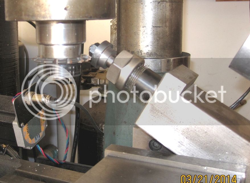
I'm using my electronic dividing head, mounted in the milling vise at a 30 degree angle. The gear pictured is the primary gear with 23 teeth. If it looks OK when I finish, I'll go ahead and make the 46 tooth cam gear. The teeth will have to be slanted in the opposite direction so the cutter will be positioned behind the gear whereas this one has the cutter in front of the gear.
Stay tuned...
Chuck
Chuck--I have to give you a big "Attaboy". You keep coming up with new things and machining operations that really impress me.---Brian
- Joined
- Aug 25, 2007
- Messages
- 3,890
- Reaction score
- 715
Chuck--I have to give you a big "Attaboy". You keep coming up with new things and machining operations that really impress me.---Brian
Thanks, Brian, I'm always looking for an easier way to do things! And I think this is going to work although it remains to be seen if the gears will be any quieter.
Here is the finished primary gear.
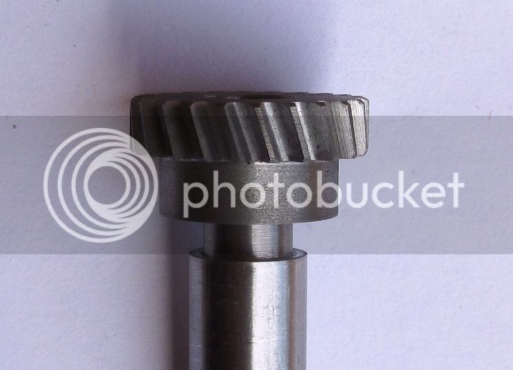
I reduced the angle to 20 degrees because I wanted to reduce the axial thrust forces between the two gears. I also had to reduce the number of teeth from 23 to 22 in order to keep the pitch diameter close to the same as with straight cut teeth. I had to use the helical gear formula for determining the tooth count/pitch diameter relationship.
I think the gear looks fine so I will go ahead and make the cam gear which will have 44 teeth.
Chuck
- Joined
- Aug 25, 2007
- Messages
- 3,890
- Reaction score
- 715
The good news is that the angle cut gears mesh properly and turn freely. The bad news is there is no discernible difference in noise level. I think the gear spacing is slightly too large, making the gears fairly loose. So, now I'm going back to straight cut gears, but remaking only the larger gear somewhat larger. Hopefully the tighter fit will overcome any mismatch in gear profile from the slightly larger size.
Chuck
Chuck
- Joined
- Aug 25, 2007
- Messages
- 3,890
- Reaction score
- 715
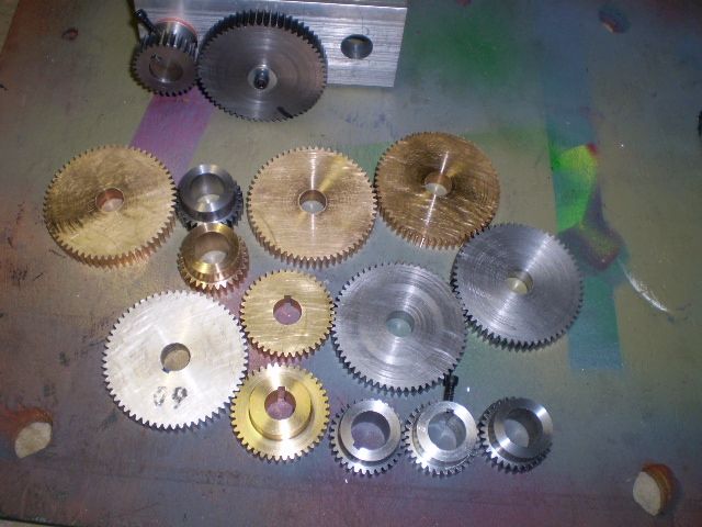
Sigh....
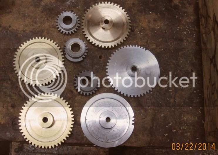
Pick your own subtitle:
a. Nobody said it was going to be easy.
b. I've never had this much trouble before.
c. Maybe that's enough practice...
d. Wonder if there's a market for these things?
BTW, one of the smaller gears pictured is OK and can be used... I think!
Chuck

Pick your own subtitle:
a. Nobody said it was going to be easy.
b. I've never had this much trouble before.
c. Maybe that's enough practice...
d. Wonder if there's a market for these things?
BTW, one of the smaller gears pictured is OK and can be used... I think!
Chuck
vascon2196
Well-Known Member
- Joined
- Oct 2, 2009
- Messages
- 1,026
- Reaction score
- 312
I think what you tried was great...helical gears are "supposed" to be quieter. Maybe just at high speeds? Either way I think its pretty cool that you did this. Keep on truckin'
If all else fails--cheat!! Put a little 600 grit lapping paste on the gears and run them for 2 or 3 minutes, then clean them up good. You have nothing to lose by doing this. and possibly something to gain.
Similar threads
- Replies
- 1
- Views
- 514


