That's what I had guessed at, thank you.
You are using an out of date browser. It may not display this or other websites correctly.
You should upgrade or use an alternative browser.
You should upgrade or use an alternative browser.
A vertical single 4-stroke IC engine
- Thread starter cfellows
- Start date

Help Support Home Model Engine Machinist Forum:
This site may earn a commission from merchant affiliate
links, including eBay, Amazon, and others.
- Joined
- Aug 25, 2007
- Messages
- 3,890
- Reaction score
- 715
Continuing to evolve my design and maybe improve it. This is my fuel-tank-mounted version, but the change will work equally well on the first one I made.
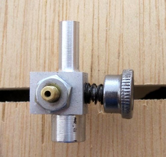
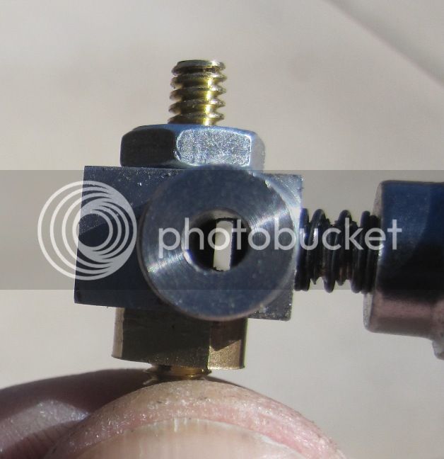
I changed the throttle control to an 8-32 screw. As the photo shows, it screws in opposite the fuel orifice in the venturi. The advantages of this control are that it should be a lot less sensitive, since full closed to full open is achieved with 3 full turns of the screw. Also, as it closes, it will keep the air flow up next to the orifice which should improve the draw and the atomization. The 8-32 screw I used is just one I found in my spares drawer, don't have any idea where it came from originally.
As a note on how changes like this occur... when I was making the carb body, I inadvertently drilled the center chamber all the way through whereas my original design called for it stop about 1/32" from the outboard end. Rather than just plug it or make a new one, I started thinking about alternative throttle arrangements and came up with this one. Of course, I've yet to try it out, but I'm hopeful it will be better.
Chuck
Teza
Well-Known Member
- Joined
- Nov 11, 2011
- Messages
- 48
- Reaction score
- 2
Hi Chuck,
To my way of thinking this last incarnation looks to be on the right track as the throttle should not adversely effect the fuel air ratio as it opens and closes, whereas the earlier design with the outboard throttle would greatly alter the mixture becoming very rich when it is closed, just my 2.5 cents (plus GST). Keep up the good work.
Cheers
Terry
- Joined
- Aug 25, 2007
- Messages
- 3,890
- Reaction score
- 715
Hi Chuck,
To my way of thinking this last incarnation looks to be on the right track as the throttle should not adversely effect the fuel air ratio as it opens and closes, whereas the earlier design with the outboard throttle would greatly alter the mixture becoming very rich when it is closed, just my 2.5 cents (plus GST). Keep up the good work.
Cheers
Terry
Yeah, Terry, I think, in theory you are right. However, didn't seem to see that in actual operation. Usually when the mixture get's too rich, especially at low speeds, the engine starts misfiring every other firing cycle.
I modified my earlier version of this carburetor to use the 8-32 screw for throttle control. Here is a video of it running on my plumbing parts engine.
https://www.youtube.com/watch?v=N-7I_IjGlC8
Seems to work well. Not quite sure why the engine continues to misfire somewhat regularly. I've checked the spark and it never seems to miss a lick. One issue with the Roy Sholl ignition system is using it with points, or in my case, a microswitch. The ignition module is supposed to fire when the points break contact. However, the circuit doesn't require much charge time and the "bounce" of the points can cause the ignition to (appear) to fire when they make contact. I've actually got the engine timed to fire on the make, but on those occasions when the engine misfires, it may be sparking on the break instead of the make. Might have to play with that some... oh, wait, I've got another engine to finish first! :facepalm:
Chuck
Hi Chuck,
I've been following your fuel mixer adventures. Interesting and it sure runs well on your pipe fitting engine.
Just to make sure I understand, the only path for the bleed air is directly into the fuel inlet/needle valve tube where it mixes with the fuel?
Also, when you are running with the main air control pretty well open, does blocking the bleed hole cause any change in engine operation?
Regards,
Chuck
- Joined
- Aug 25, 2007
- Messages
- 3,890
- Reaction score
- 715
Hi Chuck,
I've been following your fuel mixer adventures. Interesting and it sure runs well on your pipe fitting engine.
Just to make sure I understand, the only path for the bleed air is directly into the fuel inlet/needle valve tube where it mixes with the fuel?
Also, when you are running with the main air control pretty well open, does blocking the bleed hole cause any change in engine operation?
Regards,
Chuck
Hi Chuck,
Yes, to both questions. When the engine is running flat out, putting my finger over the air bleed slows it down more than half way. I haven't really played with the air bleed adjustment much. I need to try playing with the two mixer adjustments and see how they affect one another.\
Chuck

$94.99
$109.99
AHS Woodmaster 4400 Maintenance Kit for Outdoor Wood Boiler Treatment
Alternative Heating & Supplies

$39.58
$49.99
Becker CAD 12 3D - professional CAD software for 2D + 3D design and modelling - for 3 PCs - 100% compatible with AutoCAD
momox Shop
![DreamPlan Home Design and Landscaping Software Free for Windows [PC Download]](https://m.media-amazon.com/images/I/51kvZH2dVLL._SL500_.jpg)
$0.00
DreamPlan Home Design and Landscaping Software Free for Windows [PC Download]
Amazon.com Services LLC

$89.99
Outdoor Wood Boiler Water Treatment Rust Inhibitor- AmTech 300 & Test Kit
Alternative Heating & Supplies

$99.99
AHS Outdoor Wood Boiler Yearly Maintenance Kit with Water Treatment - ProTech 300 & Test Kit
Alternative Heating & Supplies

$45.99
Sunnytech Mini Hot Air Stirling Engine Motor Model Educational Toy Kits Electricity HA001
stirlingtechonline

$519.19
$699.00
FoxAlien Masuter Pro CNC Router Machine, Upgraded 3-Axis Engraving All-Metal Milling Machine for Wood Acrylic MDF Nylon Carving Cutting
FoxAlien Official

$25.34
$34.99
Bowl Sander Tool Kit w/Dual Bearing Head & Hardwood Handle | 42PC Wood Sander Set | 2" Hook & Loop Sanding Disc Sandpaper Assortment | 1/4" Mandrel Bowl Sander for Woodturning | Wood Lathe Tools
Peachtree Woodworking Supply Inc

$39.99
$49.99
Sunnytech Low Temperature Stirling Engine Motor Steam Heat Education Model Toy Kit For mechanical skills (LT001)
stirlingtechonline

$29.95
Competition Engine Building: Advanced Engine Design and Assembly Techniques (Pro Series)
Amazon.com Services LLC
Chuck--what's the latest carburetor news? I know you will come up with something incredible, and I don't want to build a carb which you have already "moved on" from because you have come up with something better. I thought the one you posted plans for seemed to work very good on your Henry Ford engine, but almost as soon as I modelled it, you were moving on to something else. I do have a model airplane carb I can use on my engine for its initial start up (That's assuming there is an initial start-up.) I am rapidly running out of things to make for my engine. About all I have to do now is put a keyway in the crankshaft and get those two arms in that the guy in Alabama is making for me.
- Joined
- Aug 25, 2007
- Messages
- 3,890
- Reaction score
- 715
Chuck--what's the latest carburetor news? I know you will come up with something incredible, and I don't want to build a carb which you have already "moved on" from because you have come up with something better. I thought the one you posted plans for seemed to work very good on your Henry Ford engine, but almost as soon as I modelled it, you were moving on to something else. I do have a model airplane carb I can use on my engine for its initial start up (That's assuming there is an initial start-up.) I am rapidly running out of things to make for my engine. About all I have to do now is put a keyway in the crankshaft and get those two arms in that the guy in Alabama is making for me.
I've uploaded my latest drawings to the download section on this board and also over at MEM. The only real departure from your modeled version is the throttle arrangement where I switched to an 8-32 screw throttle coming in from the side opposite the fuel jet. I've also decided that the air bleed hole in my original design probably doesn't add any real value, so I leave it up to the builder whether they want to include it or not.
Thx... Chuck
- Joined
- Aug 25, 2007
- Messages
- 3,890
- Reaction score
- 715
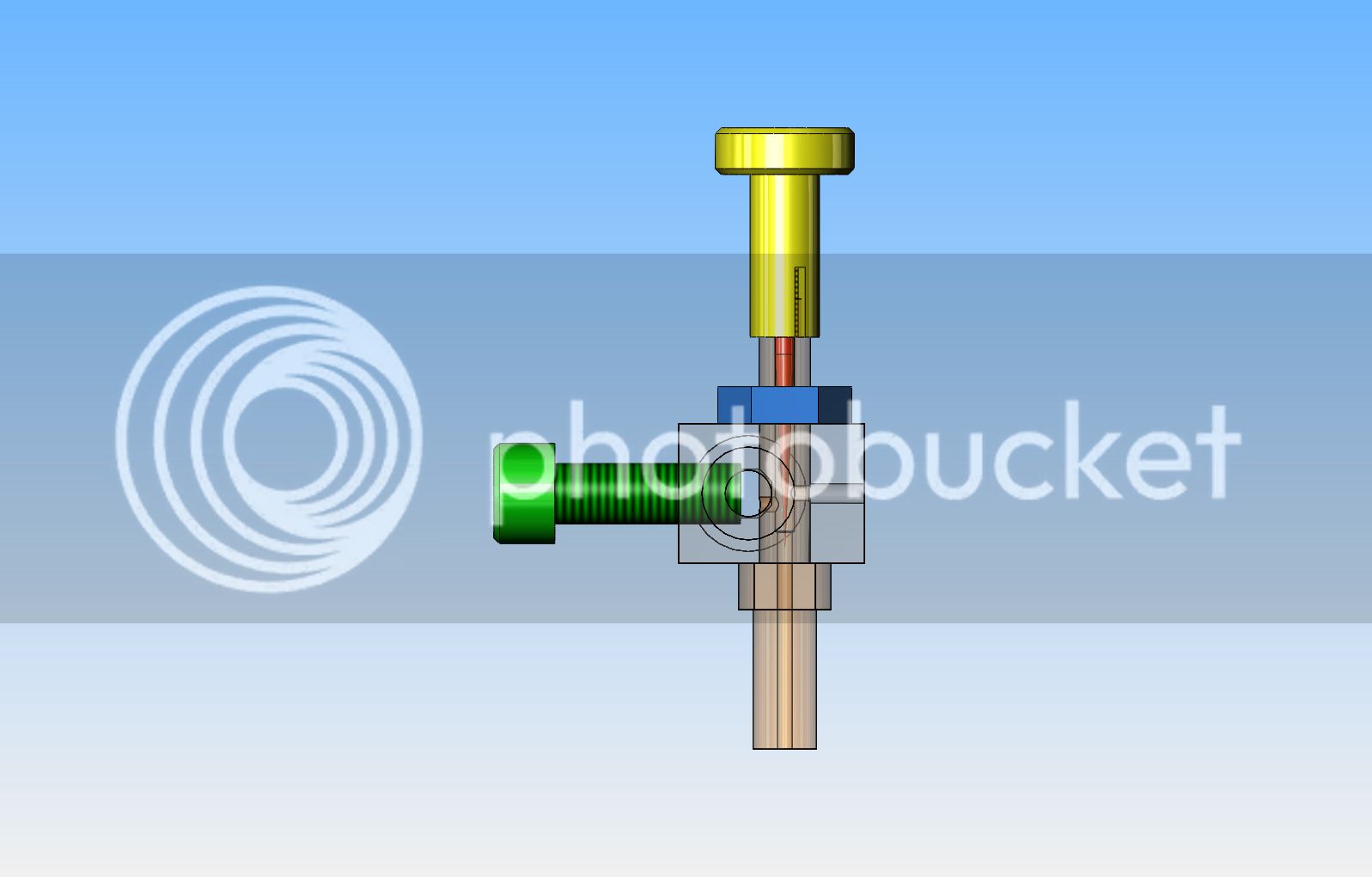
Brian, looks good except you have the vertical positioning of the fuel orifice and the air bleed holes reversed...
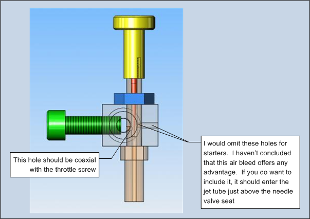
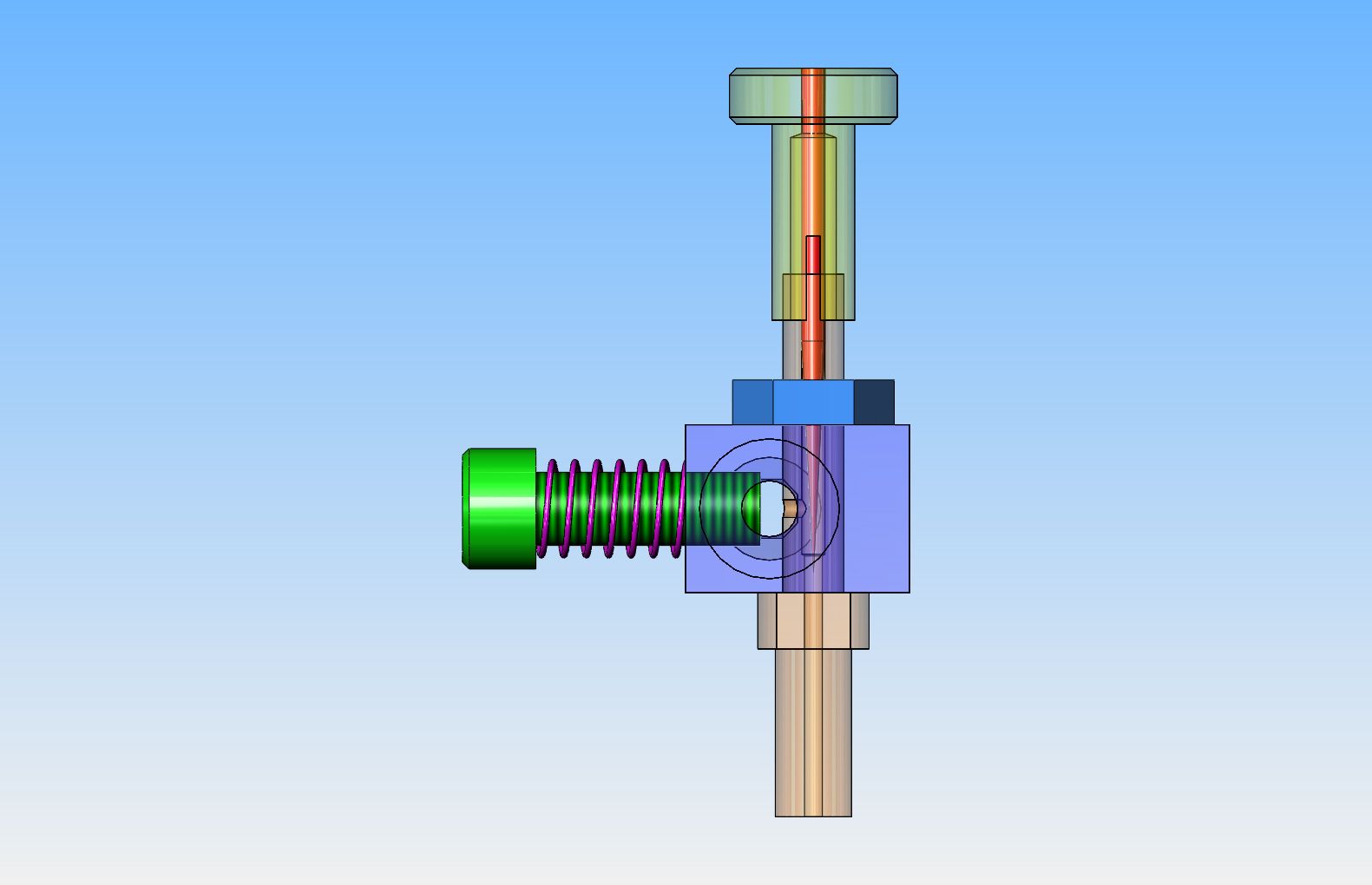
One other note is that the throttle screw needs to seat against the fuel jet when fully closed. I drilled the pilot hole with a #29 drill to the center of the venturi then finished tapping with a bottoming tap through to the opposite side of the venturi (with the fuel jet tube removed). Hope that's clear...
Chuck
Okay--Thanks Chuck---I have remodelled it and done away with the air bleed hole and lined the fuel jet hole up with the throttle screw . I have done as you suggested and tapped the throttle screw hole deep enough that I can screw the throttle screw right up tight against the fuel jet, but oddly it doesn't show up that way in the model.

Last edited:
- Joined
- Aug 25, 2007
- Messages
- 3,890
- Reaction score
- 715
Well, it runs!
[ame]http://www.youtube.com/watch?v=d8unIoDOvQA[/ame]
I've been held up trying to put the ignition together but today I thought I'd try it on a glow plug. I think it's firing too early and needs to be retarded a bit, but I'll take care of the timing when I get the spark ignition finished.
Notice also, that it's running with my latest carburetor design mounted on the fuel tanke and a polyurethane tube connecting it to the engine. That is a carb, by the way, not a vapor fuel tank!
Chuck
Looks good and robust Chuck. Also enjoy the carb illustration done by Brian. Thanks, Dave
Swifty
Well-Known Member
Looks and runs great Chuck, another one you can be proud of.
Paul.
Paul.
vascon2196
Well-Known Member
- Joined
- Oct 2, 2009
- Messages
- 1,026
- Reaction score
- 312
Great job Chuck...if and when I complete my current project, I would love to build this little guy. (or gal)...whatever gender it is!
- Joined
- Aug 25, 2007
- Messages
- 3,890
- Reaction score
- 715
Thanks everybody, for the nice words. I always appreciate the encouragement.
Phil, if you are asking about the carburetor, yes, the plans in the download section are the latest version. I'm actually hoping to clean up the drawings for the engine and post those as well.
Today I started the cleaning up and finishing process. I installed the engine on the wooden base I had previously made.
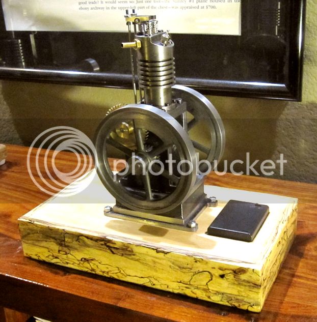
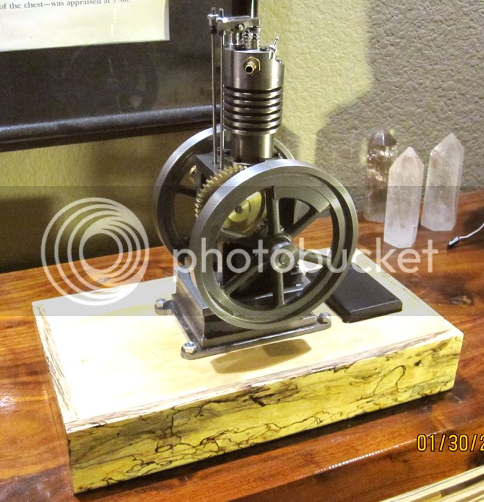
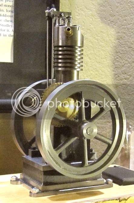
It's got a 3/4" Birch plywood top and the sides are made from Spalted Tamarind... sounds exotic, doesn't it? I had to install a new 3/16" thick plate on the bottom of the engine to provide hold-down bolt holes I could get to from the top side, rather than having to flip the base over. I also filed flats on the crankshaft for the timing gear and the flywheel set screws. The little black box is a battery case with a built in switch on top. It holds 3, AA cells and puts out 4.5 volts... Very handy! The Roy Sholl CDI unit will be mounted underneath the base.
I also installed a connecting rod that I had from earlier (don't ask why!) that is about 1/4" shorter. This lowered the compression ratio to probably around 4 to 1. It settled the engine right down, making it a lot less feisty! Much easier to start and idle down to a reasonably speed. It also doesn't jump all over the place now. I was able to start it and run it a few times after I got it all back together today and I really like the way it runs a lot better. I will definitely use a lower compression ratio on all future engines unless I'm really after performance.
Now I'm waiting on the arrival of some Futaba wiring connectors so I can get the electronic spark ignition installed.
Chuck
Phil, if you are asking about the carburetor, yes, the plans in the download section are the latest version. I'm actually hoping to clean up the drawings for the engine and post those as well.
Today I started the cleaning up and finishing process. I installed the engine on the wooden base I had previously made.


It's got a 3/4" Birch plywood top and the sides are made from Spalted Tamarind... sounds exotic, doesn't it? I had to install a new 3/16" thick plate on the bottom of the engine to provide hold-down bolt holes I could get to from the top side, rather than having to flip the base over. I also filed flats on the crankshaft for the timing gear and the flywheel set screws. The little black box is a battery case with a built in switch on top. It holds 3, AA cells and puts out 4.5 volts... Very handy! The Roy Sholl CDI unit will be mounted underneath the base.
I also installed a connecting rod that I had from earlier (don't ask why!) that is about 1/4" shorter. This lowered the compression ratio to probably around 4 to 1. It settled the engine right down, making it a lot less feisty! Much easier to start and idle down to a reasonably speed. It also doesn't jump all over the place now. I was able to start it and run it a few times after I got it all back together today and I really like the way it runs a lot better. I will definitely use a lower compression ratio on all future engines unless I'm really after performance.
Now I'm waiting on the arrival of some Futaba wiring connectors so I can get the electronic spark ignition installed.
Chuck
Philjoe5
Well-Known Member
- Joined
- Jul 12, 2007
- Messages
- 1,727
- Reaction score
- 321
Thanks Chuck for posting your build. Someday I would like to give it a try.
That is a good thing to know.
Cheers,
Phil
This lowered the compression ratio to probably around 4 to 1. It settled the engine right down, making it a lot less feisty!
That is a good thing to know.
Cheers,
Phil
Similar threads
- Replies
- 1
- Views
- 514


