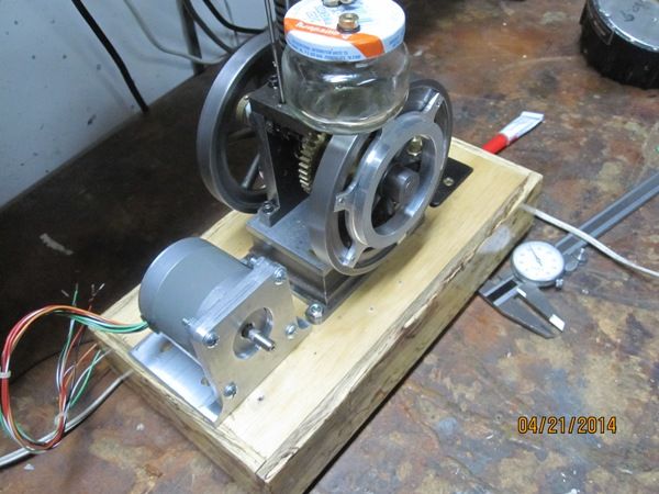
A vertical single 4-stroke IC engine

Home Model Engine Machinist Forum

Help Support Home Model Engine Machinist Forum:

This site may earn a commission from merchant affiliate links, including eBay, Amazon, and others.
Thanks, Guys.

Brian, turns out the gears were too loose. I don't think running them with grinding compound would have helped.

Chris, I think the angled gears I made were also too loose. If they had been slightly bigger, I think they would have been quieter.

So, 7 or 8 gears later, I got it resolved. Turns out the primary gear (23 teeth) was about .040" too small. If I had taken the time to measure the gears to begin with, I could have solved the problem with a whole lot less work! I made a new primary gear and kept the original Cam gear (46 teeth). It was just a tad too tight a fit so I applied some fine valve grinding compound to the gears and ran it with a drill for 5 or 10 minutes. Then I removed the gears, gave them a good cleaning, oiled them and put it back together. It's a whole lot quieter than it was and I think it will get even quieter as the gears wear against each other.

Here's a video I made today of it running...

[ame]http://youtu.be/cf8Vv8tWRCA[/ame]

I made a small brake which I can adjust with a screw to apply friction to the flywheel. Later, I'll add a generator or some other respectable load to it.

Chuck
 
  • Like
Reactions: gus
The defunct Leblonde Precision Lathe Plant,Singapore laps their gears before installing into gear box which again run for 72 hours and thereafter most of the lathe gear box run very quiet They did encounter 3--5 percent of gear boxes that fail to meet max noise level and reworked.There are lapping gears sold for the purpose of lapping freshly cut gears. KG Gears,Japan sells Lapping Gears.

The two Lblonde Lathes I had ran very quiet compared to the Chinese,Taiwanese and some UK made.

For a gear box to run very quiet,box must be sealed and enclosed and heavy gear oil topped up.

Gus has no hands on experience lapping gears .
 
Thanks, Guys.

Brian, turns out the gears were too loose. I don't think running them with grinding compound would have helped.

Chris, I think the angled gears I made were also too loose. If they had been slightly bigger, I think they would have been quieter.

So, 7 or 8 gears later, I got it resolved. Turns out the primary gear (23 teeth) was about .040" too small. If I had taken the time to measure the gears to begin with, I could have solved the problem with a whole lot less work! I made a new primary gear and kept the original Cam gear (46 teeth). It was just a tad too tight a fit so I applied some fine valve grinding compound to the gears and ran it with a drill for 5 or 10 minutes. Then I removed the gears, gave them a good cleaning, oiled them and put it back together. It's a whole lot quieter than it was and I think it will get even quieter as the gears wear against each other.

Here's a video I made today of it running...

http://youtu.be/cf8Vv8tWRCA

I made a small brake which I can adjust with a screw to apply friction to the flywheel. Later, I'll add a generator or some other respectable load to it.

Chuck

Congrats, Chuck.

Great engine. Glad you solved and fixed the noisy gears.
Are the flywheels counter-balance. Engine vibration seems to be minimal.

Your engine is on my build list.
 
Congrats, Chuck.

Great engine. Glad you solved and fixed the noisy gears.
Are the flywheels counter-balance. Engine vibration seems to be minimal.

Your engine is on my build list.
'

Thanks, Gus, the flywheels are counter-balanced.

Chuck
 
'

Thanks, Gus, the flywheels are counter-balanced.

Chuck


Hi Chuck,

My gaswork was right. Such a big mini single cylinder engine running at med speed and minmal vibration = counterbalance.
Plan to counter balance the Webster by taking off the equivalent weight of piston and con-rod. Please advise would this do as a starting point.
 
Hi Chuck,

My gaswork was right. Such a big mini single cylinder engine running at med speed and minmal vibration = counterbalance.
Plan to counter balance the Webster by taking off the equivalent weight of piston and con-rod. Please advise would this do as a starting point.

Gus, I'm not much of an authority on the dynamics of balancing an engine. The flywheels I bought from Martin Model just happened to have counter weights already cast in.

On my first Hit n Miss engine I didn't have any counterweights. So I started adding 1/2" diameter x 1/8" thick neodymium magnets on the inside of the flywheel rims opposite the crank throw. I think I started with 2 on each flywheel, then started the engine, then added another magnet to each flywheel, and started it. Finally, when I had 5 magnets on each flywheel, the engine seemed pretty well balanced. Here's a picture.

FlyWheelMagnets_zpsb101b896.jpg


My plan was to remove the magnets, weigh them, then make counter weights out of brass or steel and permanently mount them on the flywheels with screws. But, I've never gotten around to it and the magnets have held really well. Of course, the outer rim of the flywheel helps hold the magnets in place.

Chuck
 
Last edited:
Although the friction brake was a simple addition for putting a load on the engine, it's not ideal. Unfortunately, as the engine speed slows, the friction increases, so at low RPM's it becomes unpredictable. If the engine misses a lick or slows a bit on its own, it will likely stop running, pretty abruptly.

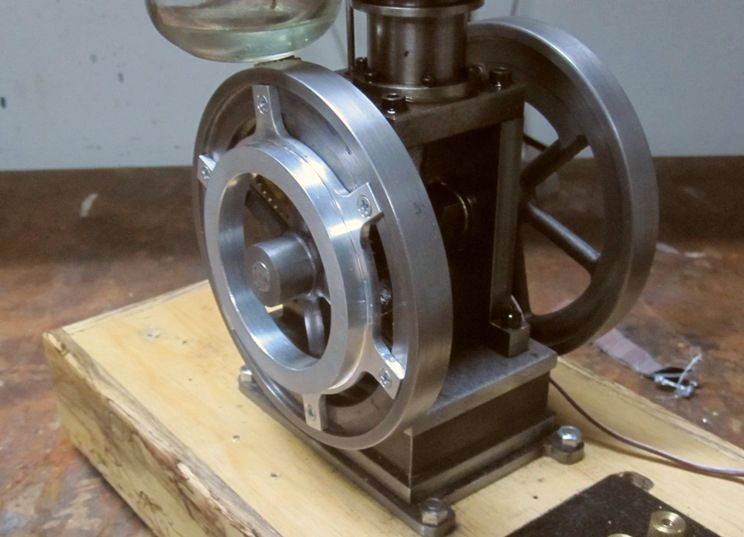
For a good engine load to keep the engine running smoothly at low RPM's what's needed is something that works like negative feedback. That is, as the engine speed slows, the braking affect lessens. I'm thinking a generator with an adjustable resistance might work better. So, today, I made a pulley which attaches to one of the flywheels.

IMG_3577_zps31d3d66a.jpg


When I get my polyflex belt, I will cut a 60 degree groove in the smaller diameter for the belt.

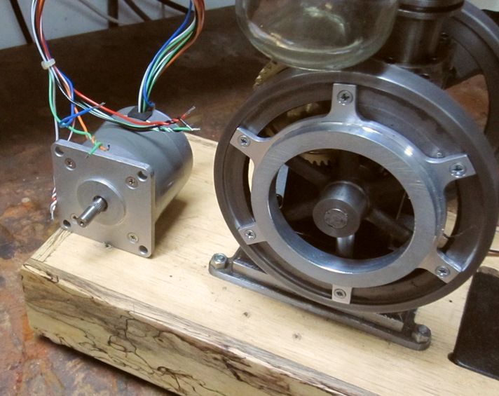
I'm going to try a stepper motor for the generator.

IMG_3578_zpse591da90.jpg


It has 4 phases so I will probably hook up a bulb to each phase with a switch. Then I can adjust the load by switching in more or fewer phases.

Chuck
 
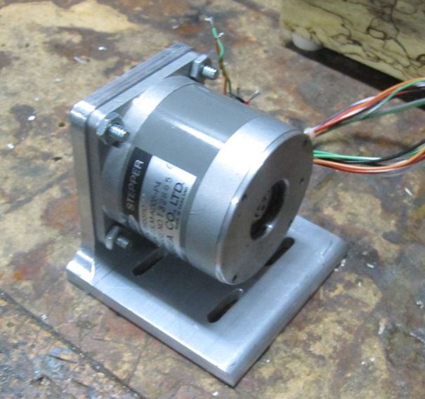
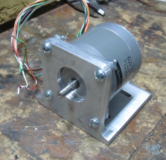
Today I made a mounting base for the Stepper (soon to be alternator).

IMG_3579_zps8f535185.jpg


IMG_3580_zpsff030a10.jpg


IMG_3581_zps8cf1b88b.jpg


If this functions well as a load for the engine, I'm thinking of making a case for the stepper that makes it look more like a vintage dynamo. Seems like a good application for a 3D printer.

Chuck
 
Gus, I'm not much of an authority on the dynamics of balancing an engine. The flywheels I bought from Martin Model just happened to have counter weights already cast in.

On my first Hit n Miss engine I didn't have any counterweights. So I started adding 1/2" diameter x 1/8" thick neodymium magnets on the inside of the flywheel rims opposite the crank throw. I think I started with 2 on each flywheel, then started the engine, then added another magnet to each flywheel, and started it. Finally, when I had 5 magnets on each flywheel, the engine seemed pretty well balanced. Here's a picture.

FlyWheelMagnets_zpsb101b896.jpg


My plan was to remove the magnets, weigh them, then make counter weights out of brass or steel and permanently mount them on the flywheels with screws. But, I've never gotten around to it and the magnets have held really well. Of course, the outer rim of the flywheel helps hold the magnets in place.

Chuck


Will monkey see/monkey do. Bought some magnets. No matter how many magnets put,I can only reduce the residue force to a minimum. Was working on big single stage,double acting(100--200hp) air compressor,boils down to a big&thick slab of concrete to absorb the residue force.
 
Chuck--a quick question. I see that you are running an open crank-case. What do you use for a bearing on the small end of the con rod, and how do you oil it?---Brian
 
Hey Brian,

There is no bearing or bushing, just the aluminum rod running on the steel crankshaft. It's fastened on with a rod cap in the standard fashion. I just squirt a little oil on it now and then. It also gets quite a bit of oil-like substance that makes it's way past the piston and drips down the rod. Seems to work OK.

Chuck
 
Back
Top