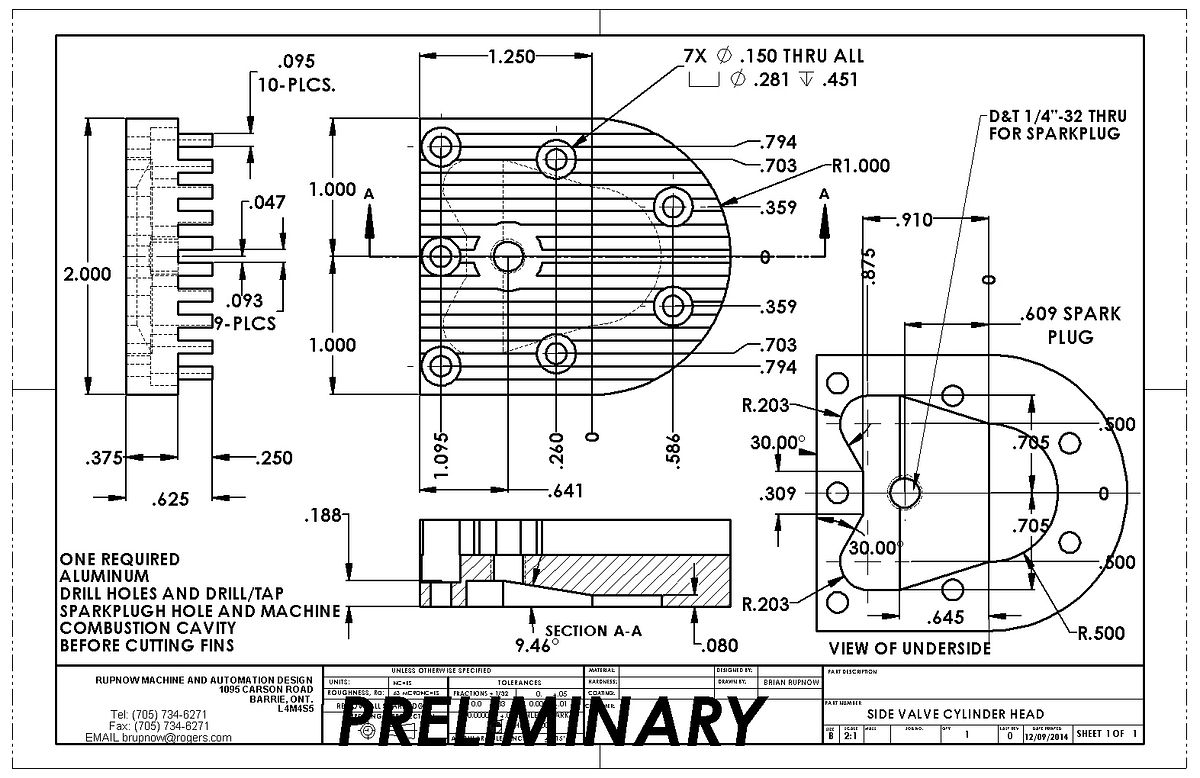
Yeah gunna--I like that. There is more heat at the top of the cylinder, so the fins have to be thinner there to dissipate more heat. That's my story and I'm sticking to it!!!---Brian
You are using an out of date browser. It may not display this or other websites correctly.
You should upgrade or use an alternative browser.
You should upgrade or use an alternative browser.
A new engine for fall---
- Thread starter Brian Rupnow
- Start date

Help Support Home Model Engine Machinist Forum:
This site may earn a commission from merchant affiliate
links, including eBay, Amazon, and others.
I don't post a lot of "in process" shots anymore, but tonight I thought I would put up a shot of the beginning of the aluminum combustion chamber. I have marked out the outer profile, bored the 1" through hole, and the 1.160" diameter counterbore. You can see the cylinder setting on the end of the work. When I bore holes to a critical fit, I do a lot of "try it and see if it fits yet" with the mating pieces. After a summer of engineering work avoidance, some of my customers are calling me up and asking to have their projects worked on "Right Now", and if I ignore these folks they find someone else and I never hear from them again. Between the engineering work and work fixing up the house I bought, I am sometimes hard pressed to find a bit of time to machine my own stuff.

Swifty
Well-Known Member
It's a real bummer when work gets in the way of your hobby, but I guess the money will allow you to buy a few special things.
Paul.
Paul.
SixSixSevenSeven
Active Member
- Joined
- Jul 11, 2014
- Messages
- 25
- Reaction score
- 3
Yeah gunna--I like that. There is more heat at the top of the cylinder, so the fins have to be thinner there to dissipate more heat. That's my story and I'm sticking to it!!!---Brian
I'm normally more into electronics and software than machining, but reminds me of a classic quote: "Its not a bug, its a feature"
I still have some fin cutting and finessing to do, but this is getting quite exciting!!! I have to buy some material to make a fixture to mount this combustion chamber in the 3 jaw chuck on my rotary table to let me cut the cooling slot that runs around the perimeter. There is a lot of work in this part, but I am pleased with how it is turning out.

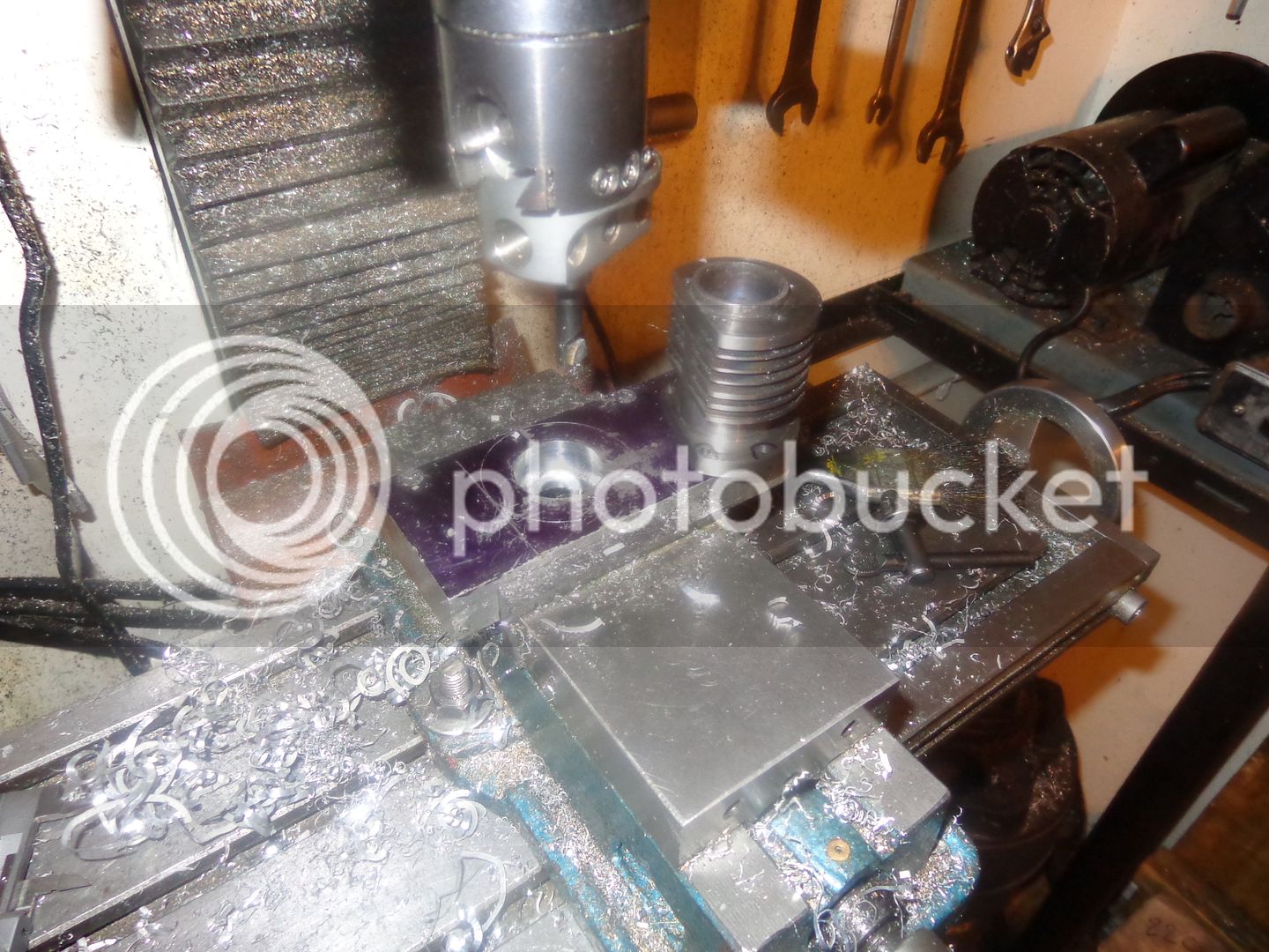
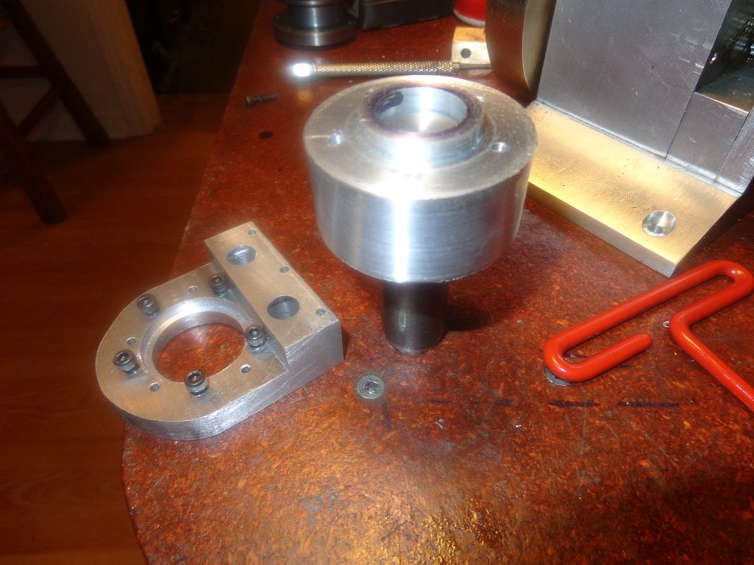
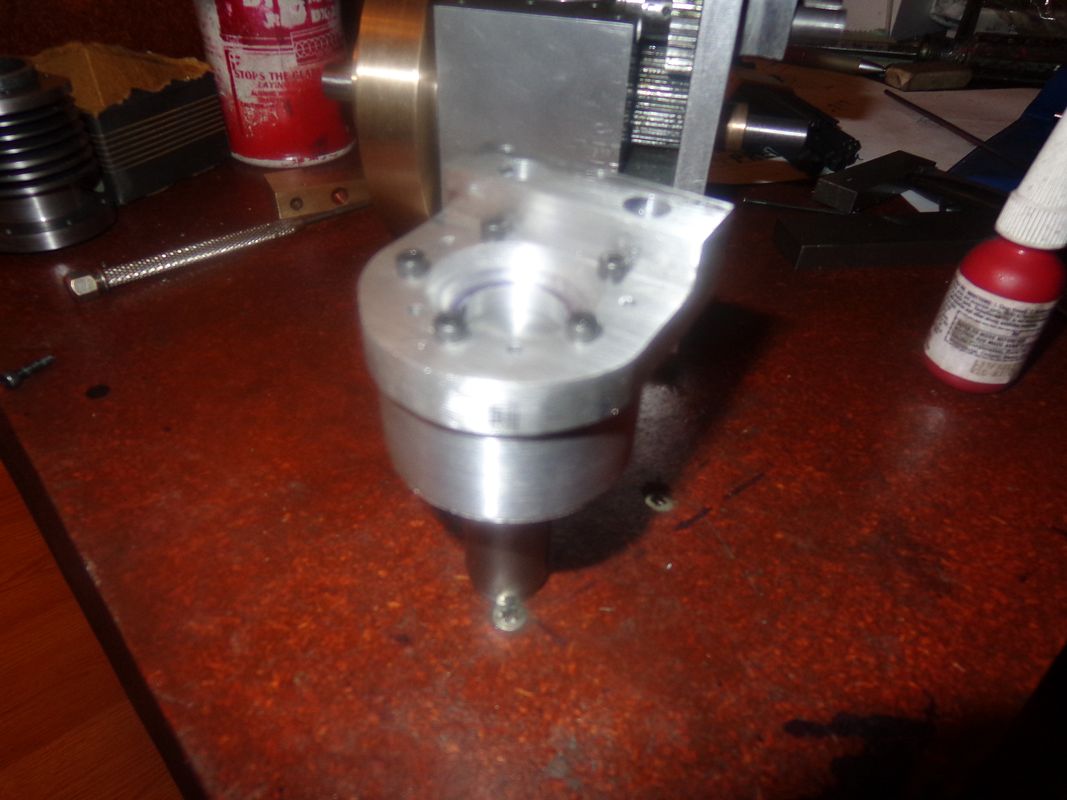
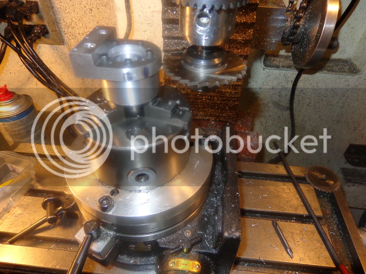
For those of you who wondered about the fixture I would make to cut the groove in the combustion chamber and to round the curved side of it, here is how I am going to do it. I found a suitable piece of 2" round aluminum and bored it for a hard press fit of a 3/4" crs shaft. I then set it up in the lath and turned a spigot on the face to be a precision fit into the 1" bore side of the combustion chamber. I then drilled and tapped five #5-40 holes in it and bolted the combustion chamber to it, using bolt holes which were already in the combustion chamber. The third picture shows it set up in my milling machine with a 0.093" slitting saw mounted in the spindle arbor. In order to take a quick picture, I put the slitting saw arbor in my 3 jaw chuck. In reality, it will be mounted in a collet held in the mill spindle by the drawbar.


$39.58
$49.99
Becker CAD 12 3D - professional CAD software for 2D + 3D design and modelling - for 3 PCs - 100% compatible with AutoCAD
momox Shop

$519.19
$699.00
FoxAlien Masuter Pro CNC Router Machine, Upgraded 3-Axis Engraving All-Metal Milling Machine for Wood Acrylic MDF Nylon Carving Cutting
FoxAlien Official

$45.99
Sunnytech Mini Hot Air Stirling Engine Motor Model Educational Toy Kits Electricity HA001
stirlingtechonline

$89.99
Outdoor Wood Boiler Water Treatment Rust Inhibitor- AmTech 300 & Test Kit
Alternative Heating & Supplies

$94.99
$109.99
AHS Woodmaster 4400 Maintenance Kit for Outdoor Wood Boiler Treatment
Alternative Heating & Supplies

$24.99
$34.99
Bowl Sander Tool Kit w/Dual Bearing Head & Hardwood Handle | 42PC Wood Sander Set | 2" Hook & Loop Sanding Disc Sandpaper Assortment | 1/4" Mandrel Bowl Sander for Woodturning | Wood Lathe Tools
Peachtree Woodworking Supply Inc
![DreamPlan Home Design and Landscaping Software Free for Windows [PC Download]](https://m.media-amazon.com/images/I/51kvZH2dVLL._SL500_.jpg)
$0.00
DreamPlan Home Design and Landscaping Software Free for Windows [PC Download]
Amazon.com Services LLC

$99.99
AHS Outdoor Wood Boiler Yearly Maintenance Kit with Water Treatment - ProTech 300 & Test Kit
Alternative Heating & Supplies

$39.99
$49.99
Sunnytech Low Temperature Stirling Engine Motor Steam Heat Education Model Toy Kit For mechanical skills (LT001)
stirlingtechonline
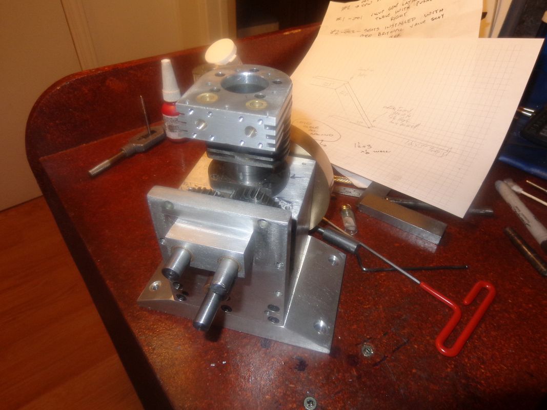
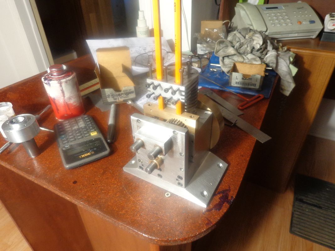
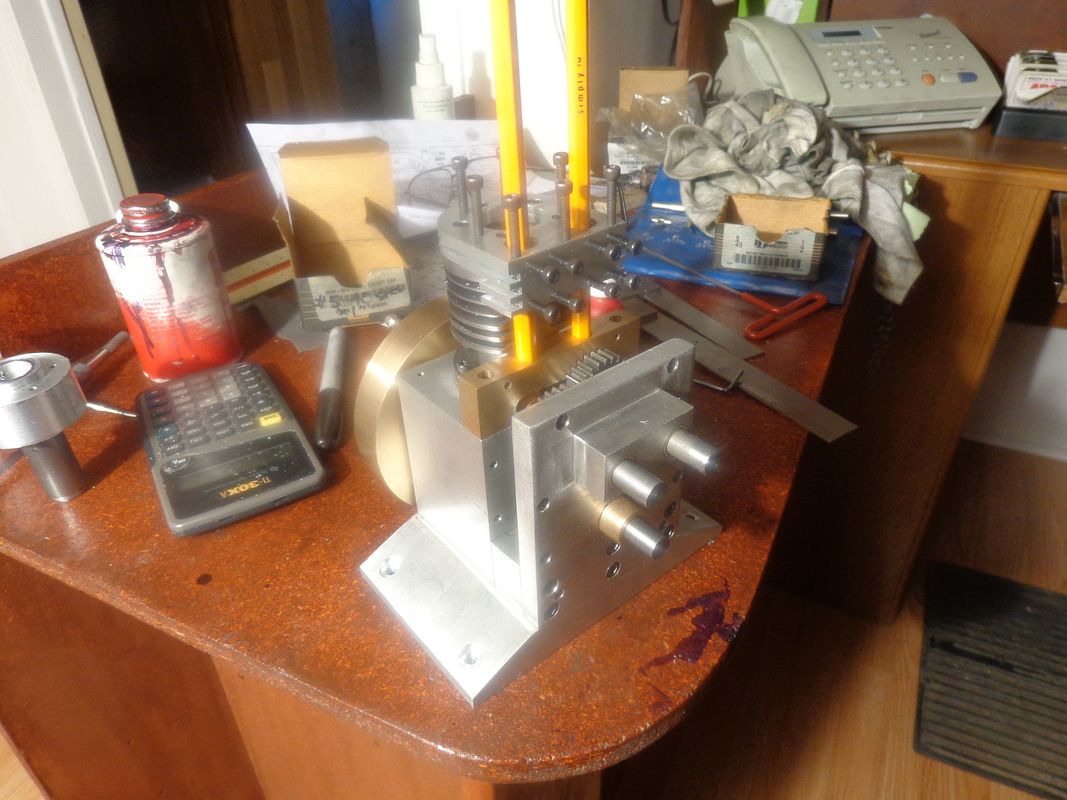
I get a great sense of accomplishment (and sometimes astonishment) when everything actually bolts together, and all of those random lumps of steel and aluminum begin to look like an engine. Today I have reached that point. The combustion chamber turned out great, and my experience with the .093 slitting saw was a success. The two yellow pencils indicate where the valves and tappets are going to be.Although there are many different directions I could jump in right now, I am anxious to see what the "overall" engine is going to look like, so I think I will machine the cylinder head next.


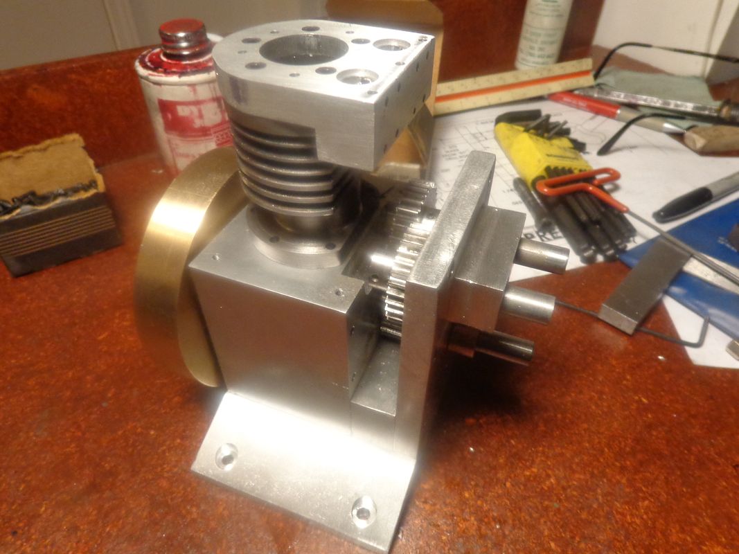
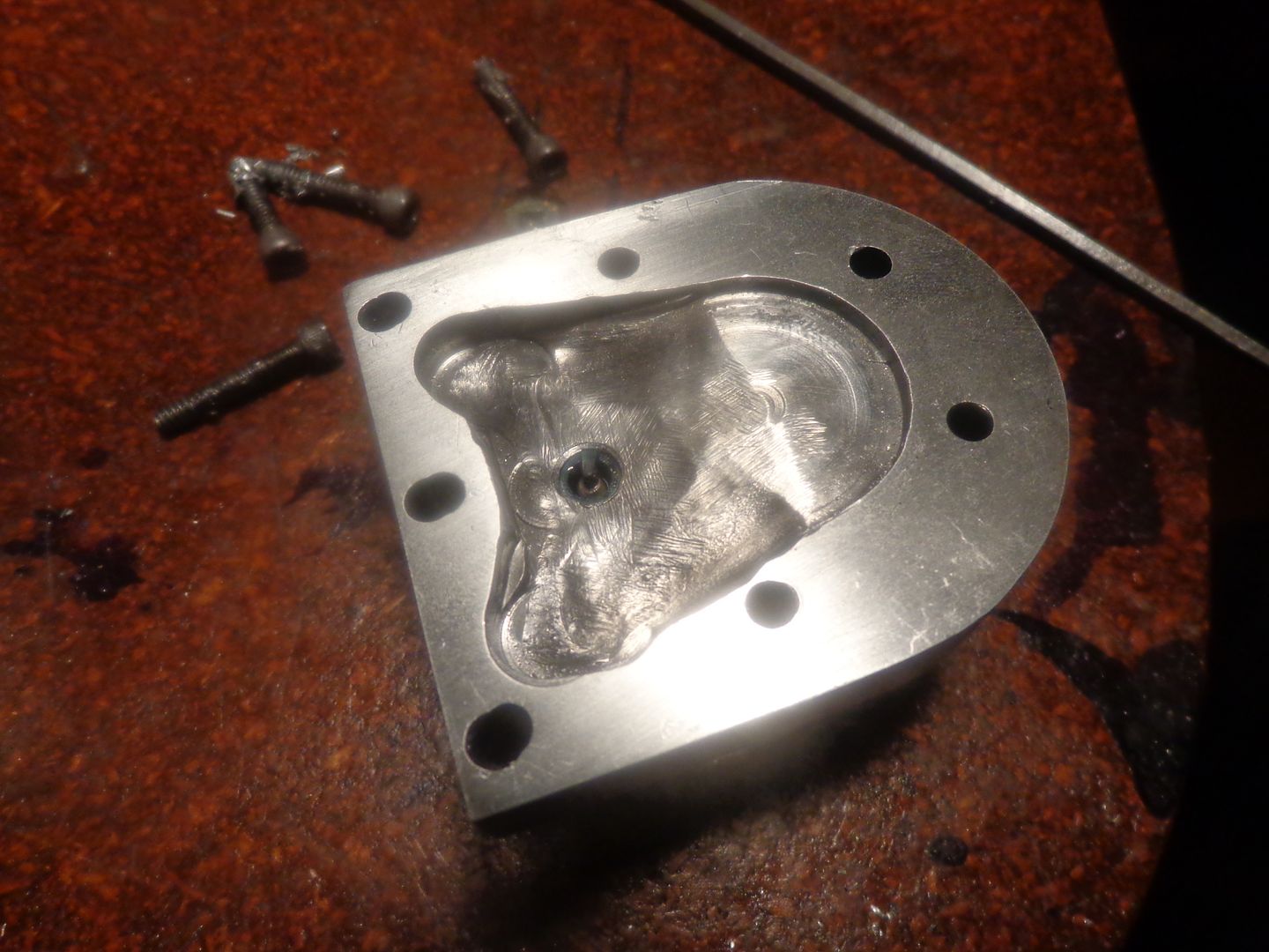
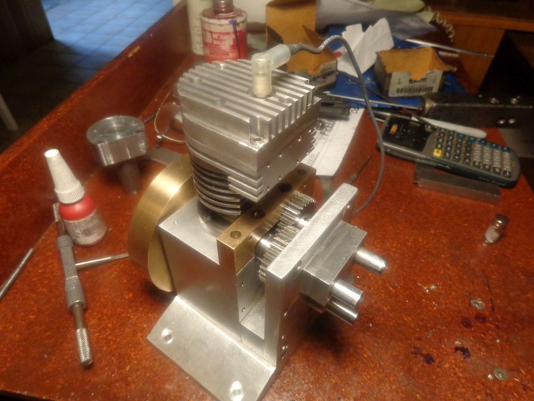
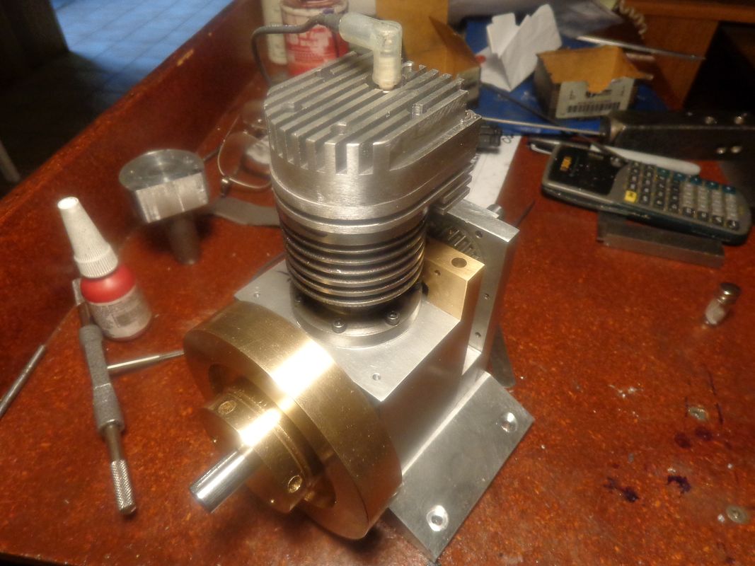
Now I know what I DON'T want to be when I grow up!!!---A cooling fin slot cutter!! The .093" slitting saw works amazingly well, but at 0.100" depth of cut, thats 4 passes per fin-slot x 11 slots = One heck of a lot of cranking on a manual mill. The sparkplug is a 1/4"-32 Rimfire plug from Roy Sholl. I didn't get too crazy finishing the bit of combustion chamber inside the head. It will work just as well the way I have it as it would polished.--In fact, it might work even better. I am really pleased with the way the engine is looking.---Brian


Swifty
Well-Known Member
Nice work on the head, when I saw your drawing I thought you made life difficult with the tapered combustion profile, but it came out well. Am I allowed to ask about the 3 elongated bolt holes on the valve end?
Paul.
Paul.
Sharp eyes, Swifty!! I made a mistake in the placement of the 3 tapped holes in the combustion chamber, and didn't notice it. Then when I made the cylinder head to the drawing, the bolts wouldn't screw into the combustion chamber. It wasn't out by very much, so I "stretched" the holes. ---Didn't even have to stretch the counterbores, it was that close.
It's a bit late in the game to be figuring this out, but just for the heck of it I ran a quick calculation to see what the compression ratio on this engine was going to be. Without taking the heads of the valves into consideration, the compression ratio is a whopping 4.8:1----------That is about what I had figured it would be, but it's nice when the math confirms it.
Swifty
Well-Known Member
Brian, when stretching bolt down holes, metric cap screws are great. The shoulder on the cap head is very wide compared to imperial screws. In the old days, when we used imperial screws, I loathed 5/16" BSW cap screws, the head shoulder was so small compared to the shank that when we stretched holes it was very dicey.
Often near the end of a working day, I would follow up with the employees as to the progress they were making on the work, more often than not (much to their embarrassment) I would spot mistakes straight away, still, so long as it didn't impact the finished item it was ok.
Paul.
Often near the end of a working day, I would follow up with the employees as to the progress they were making on the work, more often than not (much to their embarrassment) I would spot mistakes straight away, still, so long as it didn't impact the finished item it was ok.
Paul.
Last edited:
I hate it when I design the part correctly, make the drawing correctly, then mis-read my own drawing and machine the part wrong!!!
Todays offering to the machining Gods is a piston. Granted, its a rather strange looking piston, and I have never built one like this before, but remember, we are in the wonderful world of prototype here. The top section of the piston extends up beyond the split between the combustion chamber and the cylinder, so we don't want it to contact the wall of the combustion chamber in that area. Additionally, there is more "hogging out" of material in the rod end of the cylinder than is usual. That is to accommodate the 1/4" sealed needle roller bearing, which is the smallest size I was able to buy. I'm not even certain a needle roller bearing is going to give us any great benefit there in terms of reducing friction, because the rod only swings in a small arc, not a full rotation.
I have to contact the manufacturers of the needle bearings on Monday, as I remember reading somewhere that needle bearings are made deliberately oversize, both on the outer diameter and on the inner diameter. They are intended to be press fitted into a housing, with a hard enough press fit to reduce the bore to the correct size.--That could be quite a trick, when they are going into an aluminum rod with only a thin band of material enclosing the bearings.
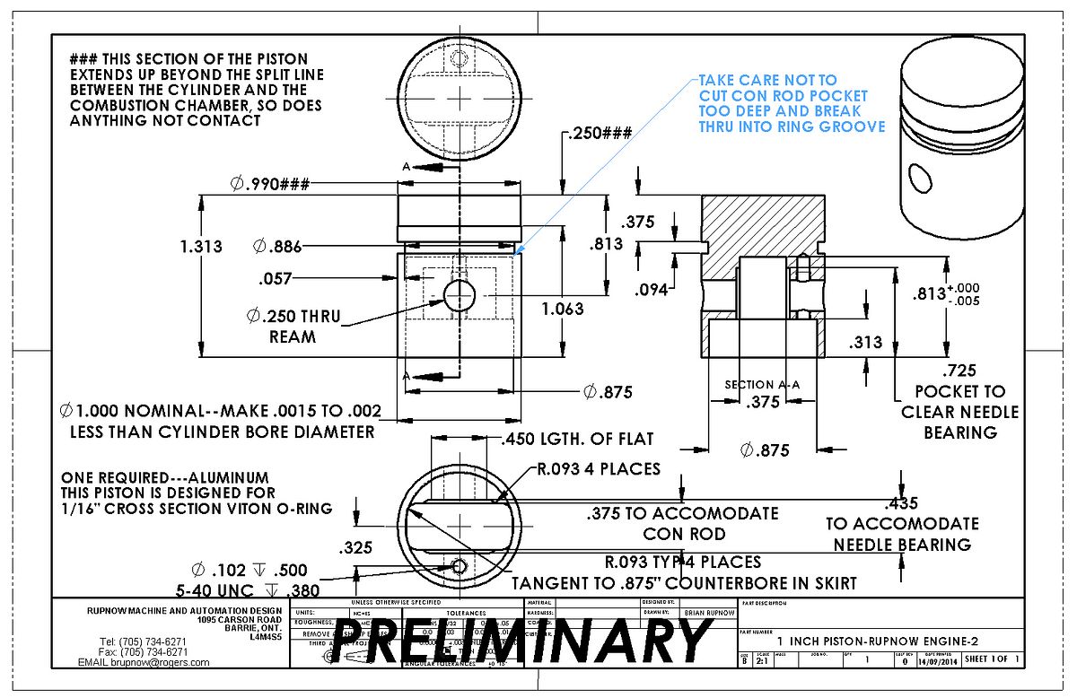
I have to contact the manufacturers of the needle bearings on Monday, as I remember reading somewhere that needle bearings are made deliberately oversize, both on the outer diameter and on the inner diameter. They are intended to be press fitted into a housing, with a hard enough press fit to reduce the bore to the correct size.--That could be quite a trick, when they are going into an aluminum rod with only a thin band of material enclosing the bearings.

I was getting ahead of myself!! Before I make the piston I have to lap the cylinder bore. Before I lap the cylinder bore I have to figure out a gasket to go between the cylinder and the combustion chamber and permanently lock them together. Before I do that I might as well make the valve cages and install them. So---These are the valve cages, which act not only as a seat for the valve to close against, but also as a guide for the valve stem. People have made these valve cages from many different materials, but I find that brass seems to work well, and an added advantage is that the brass cage, being softer than the steel valve, will "conform" to the shape of the valve face after the engine has been run for a short period of time, providing an excellent seal for compression.--And--If you do happen to screw up a valve seat, then you only have to replace this small item, not an entire cylinder head or whatever it is pressed into.
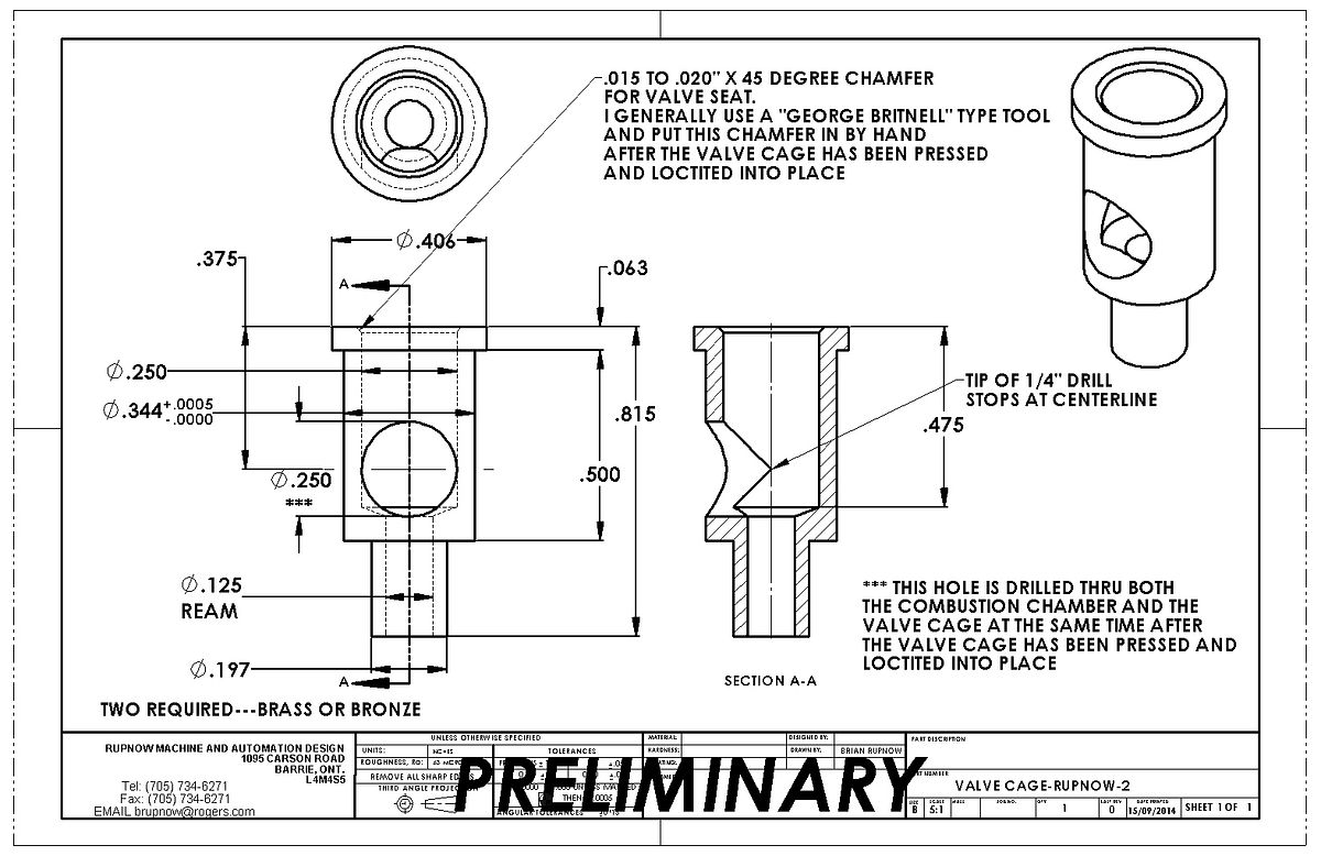

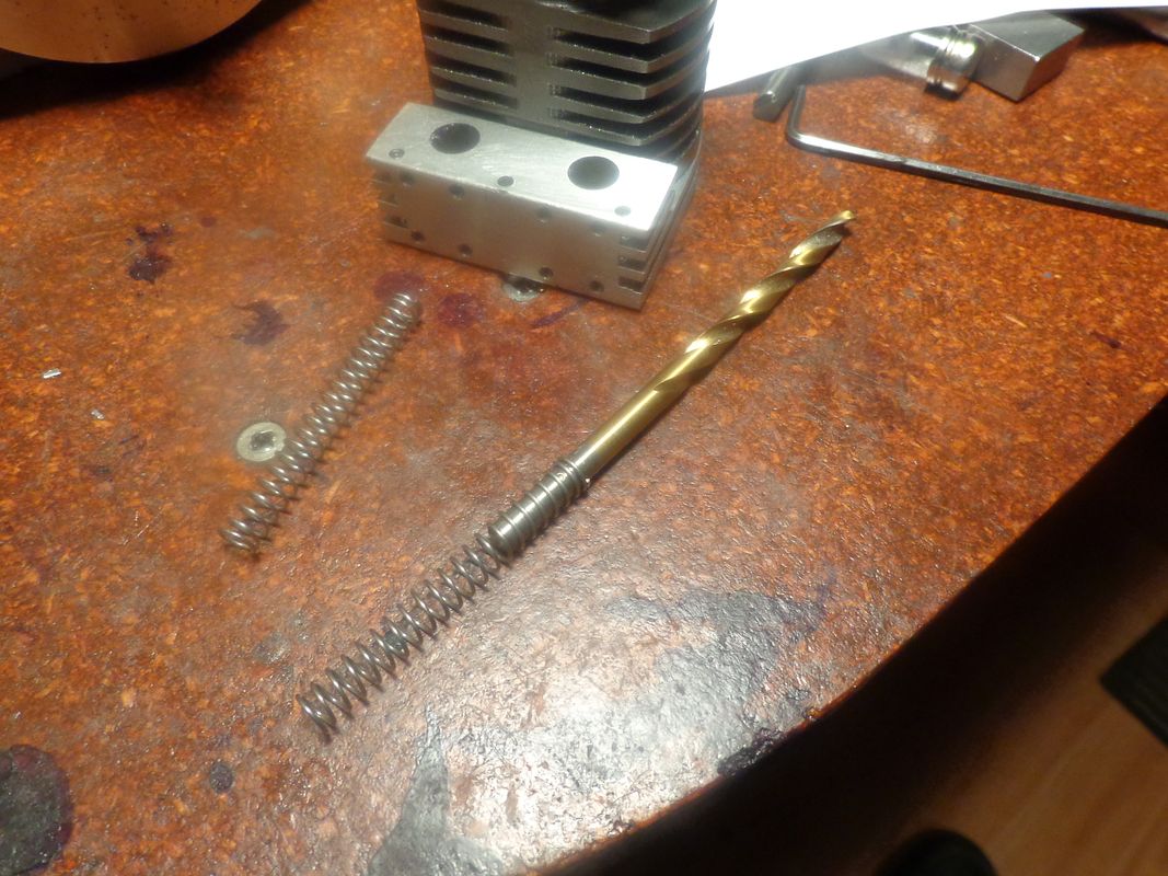
Hmmmm---Everything I do has consequences--- I had to go out this morning to buy some brass to make valve cages out of. While I was out and about, I got thinking about the 0.197" diameter on the cages. Started thinking, that if I found out after the fact that the .197" diameter was too large to fit into a spring comfortably, there was no way to change it after it was pressed and Loctited into place. So---I stopped at the tool shop and bought a .197" diameter drill. Then I stopped at my fastener supplier and dug around in his spring collection. I ended up buying a pair of springs "INDUS0615125" They are a tight fit onto a .197" drill. Consequently, I will reduce that diameter on the cage drawing to .193" diameter. In the picture that is a .193" diameter drill setting inside the spring, and it fits well with no binding. The spring is wound from .023" diameter wire, has a pitch of .090 between the coils, and each spring is approximately 2" long, free length, but they will be cut down to a shorter length when I install them.

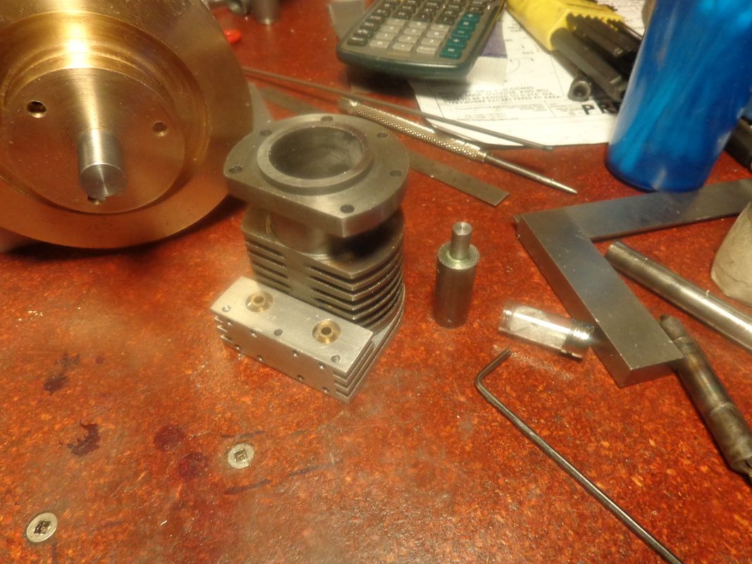
So now we have a pair of valve cages installed. The first picture shows one of the semi-completed valve cages laying beside the cylinder, with the "pusher tool' that I use in my mechanics vice for pushing the cages into place. The valve seat is not cut yet in that picture, and the hole which lets fuel or exhaust enter/exit from the cages are not yet drilled.
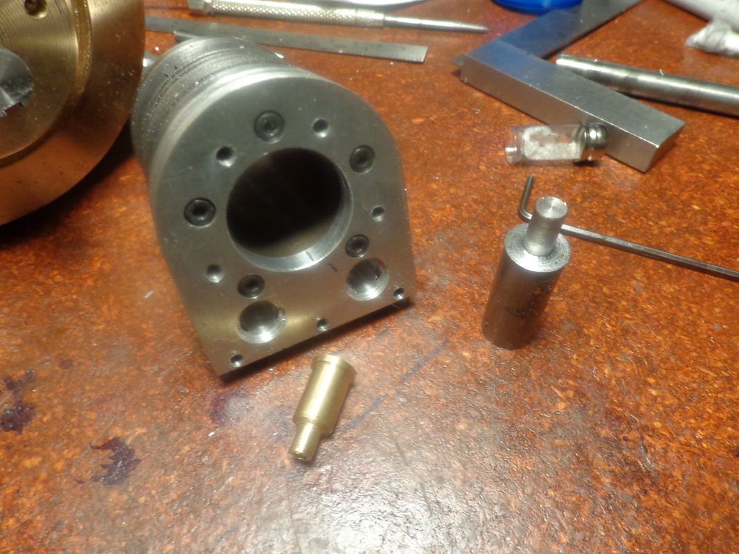

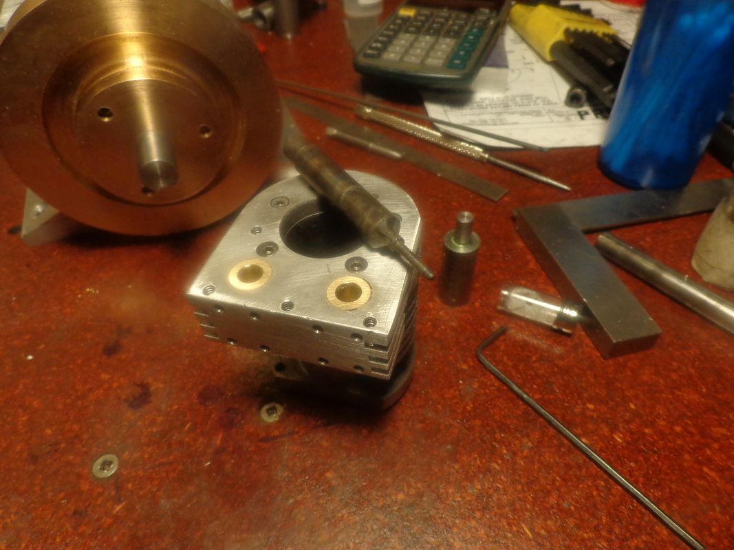
In these two pictures you can see the underside of the valve cages in one shot, and the top of the cylinder and valve cages in the other. In the shot showing the top of the cylinder, you can see my "George Britnell valve seat cutting tool". The seats are cut in that picture, but are hard to see because they are very small. They are cut by hand---no power tool involved.


Similar threads
- Replies
- 95
- Views
- 12K
- Replies
- 22
- Views
- 2K


