You are using an out of date browser. It may not display this or other websites correctly.
You should upgrade or use an alternative browser.
You should upgrade or use an alternative browser.
A new engine for fall---
- Thread starter Brian Rupnow
- Start date

Help Support Home Model Engine Machinist Forum:
This site may earn a commission from merchant affiliate
links, including eBay, Amazon, and others.
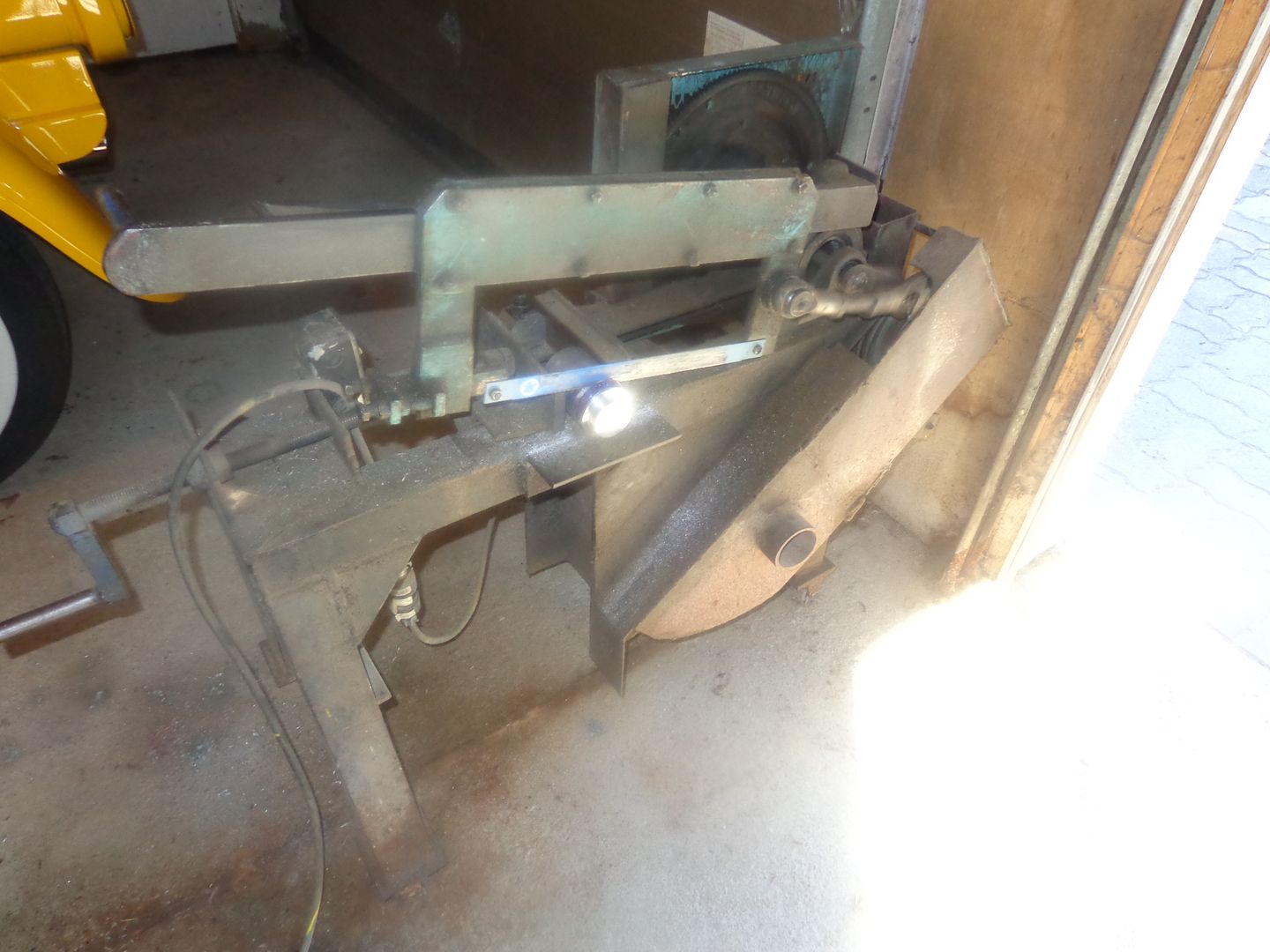
After initially turning one end of the 2 1/2" diameter aluminum to size, I tried to cut the 6" length down in my little 14" bandsaw, but it kept grabbing and wanting to rotate in my hands. So---I walked it out to the main garage, where I keep my old monster power hacksaw that I built almost 40 years ago. It is self feeding and will saw anything up to a 5" diameter billet. It seldom gets used anymore, but on a job like this it earns it's keep!!!
Today I'm going to start out making this part. If all goes well, I may even get to the base plate.
Today I'm going to start out making this part. If all goes well, I may even get to the base plate.

And here we have it with the "poll approved' baseplate. In the rear view you can see the two 3/16" diameter alignment pins which fit into holes reamed thru all 3 pieces which bolt together to maintain alignment. You can also see the rear crankshaft bushing which extends 3/8" out past the backplate for my ignition point mounting plate to register on, to give me variable timing while the engine is running. The 3/8" shaft setting in the bushing is just a long piece of 3/8" rod used for a temporary alignment rod for the bushings.


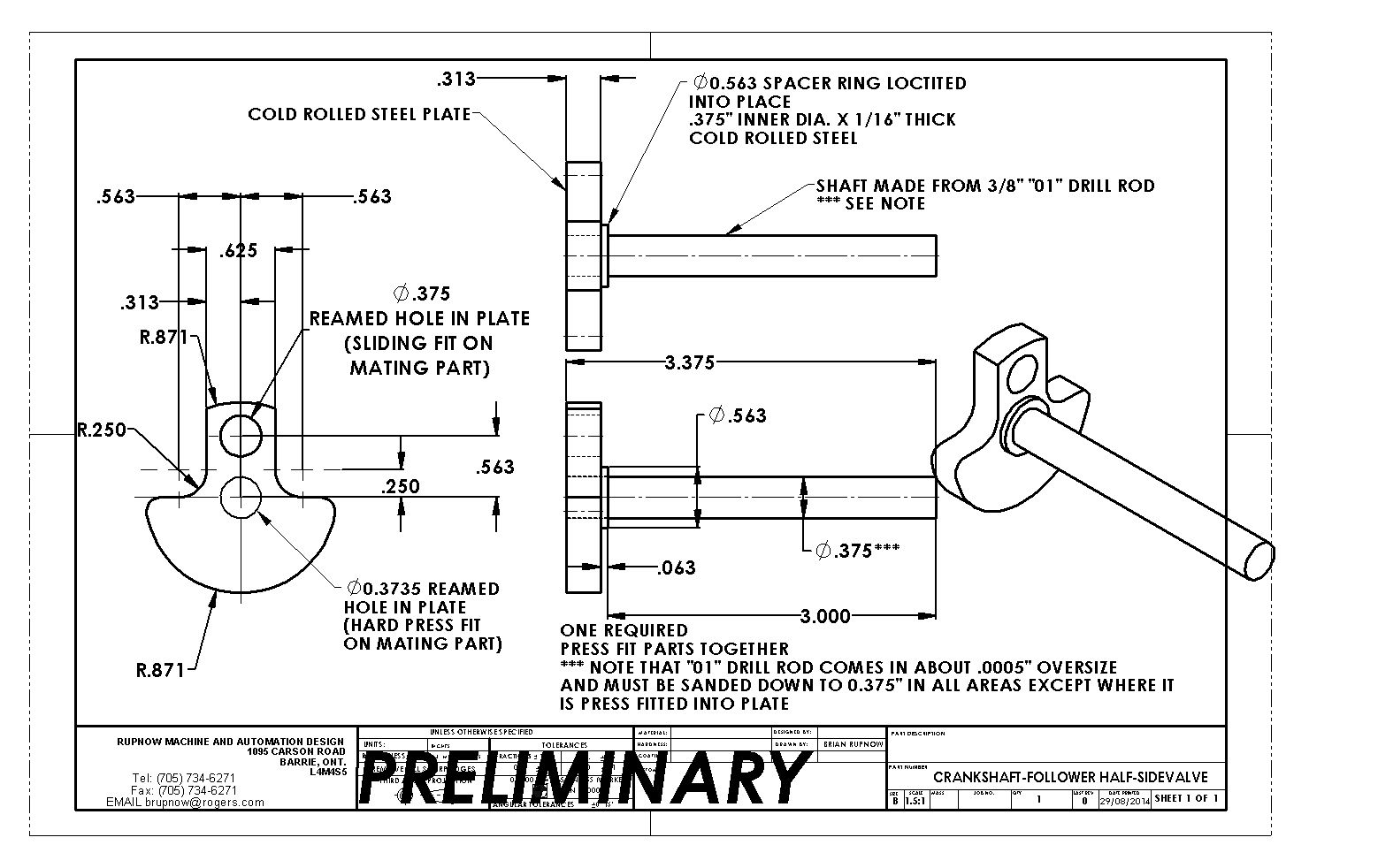
So far, on this build, I have been making great speed machining the comparatively "easy" parts. I consider the hardest parts will probably be the cylinder and the combustion chamber, so I'm shying away from them so far. I guess that before I go much farther, I better have a crankshaft. It is a two piece crankshaft, which I haven't made before, with a primary half and a follower half. The fact that it is two piece lets me run a con rod with a needle bearing in the big end, which is not split.



Last edited:
![DreamPlan Home Design and Landscaping Software Free for Windows [PC Download]](https://m.media-amazon.com/images/I/51kvZH2dVLL._SL500_.jpg)
$0.00
DreamPlan Home Design and Landscaping Software Free for Windows [PC Download]
Amazon.com Services LLC

$39.58
$49.99
Becker CAD 12 3D - professional CAD software for 2D + 3D design and modelling - for 3 PCs - 100% compatible with AutoCAD
momox Shop

$89.99
Outdoor Wood Boiler Water Treatment Rust Inhibitor- AmTech 300 & Test Kit
Alternative Heating & Supplies

$45.99
Sunnytech Mini Hot Air Stirling Engine Motor Model Educational Toy Kits Electricity HA001
stirlingtechonline

$24.99
$34.99
Bowl Sander Tool Kit w/Dual Bearing Head & Hardwood Handle | 42PC Wood Sander Set | 2" Hook & Loop Sanding Disc Sandpaper Assortment | 1/4" Mandrel Bowl Sander for Woodturning | Wood Lathe Tools
Peachtree Woodworking Supply Inc

$519.19
$699.00
FoxAlien Masuter Pro CNC Router Machine, Upgraded 3-Axis Engraving All-Metal Milling Machine for Wood Acrylic MDF Nylon Carving Cutting
FoxAlien Official

$99.99
AHS Outdoor Wood Boiler Yearly Maintenance Kit with Water Treatment - ProTech 300 & Test Kit
Alternative Heating & Supplies

$39.99
$49.99
Sunnytech Low Temperature Stirling Engine Motor Steam Heat Education Model Toy Kit For mechanical skills (LT001)
stirlingtechonline

$94.99
$109.99
AHS Woodmaster 4400 Maintenance Kit for Outdoor Wood Boiler Treatment
Alternative Heating & Supplies
Nothing of real importance machined in the last two days. I moved my son and his family from a rented townhouse into the house I bought two weeks ago. My Gawd!!! I never realized you could collect so much junk after living in a townhouse for ten years. He only had to move about 1/4 mile, so I moved him with my little Ford Ranger, and he had a friend to help with the heavy lifting. I think it took about 16 trips, but we got everything moved between 8 in the morning and four in the afternoon, except the barbecue, which we forgot. Went back and got it this morning. The new house currently looks like a disaster area, but him and his wife can sort that out this week coming. The kids will be able to start in their new schools on Tuesday. I had good intentions of starting work on the crankshaft, but this afternoon I'm too pooped to participate.
Swifty
Well-Known Member
I've helped the kids move a couple of times, the first time was with a 7x4 trailer, well after that experience, I paid for the hire of a large truck with hydraulic tailgate every other time, it was so much easier.
Paul.
Paul.
Cogsy
Well-Known Member
I've just closed my furniture removals business after 8+ years and I can tell you it's a lot easier to hire professionals than doing it yourself. Having said that, I hate to move myself (all that packing and unpacking), I've lived in my 3 bed, 1 bath house with my wife and 4 kids for 15 years and I have no intention of moving.
The engine is looking great Brian and I realise it's way too late to make changes, but I have a suggestion to include in your next project - design and cut your own helical gears. I just finished researching it and thanks to Chuck Fellows' fixture design, it's not as difficult as it sounds.
The engine is looking great Brian and I realise it's way too late to make changes, but I have a suggestion to include in your next project - design and cut your own helical gears. I just finished researching it and thanks to Chuck Fellows' fixture design, it's not as difficult as it sounds.
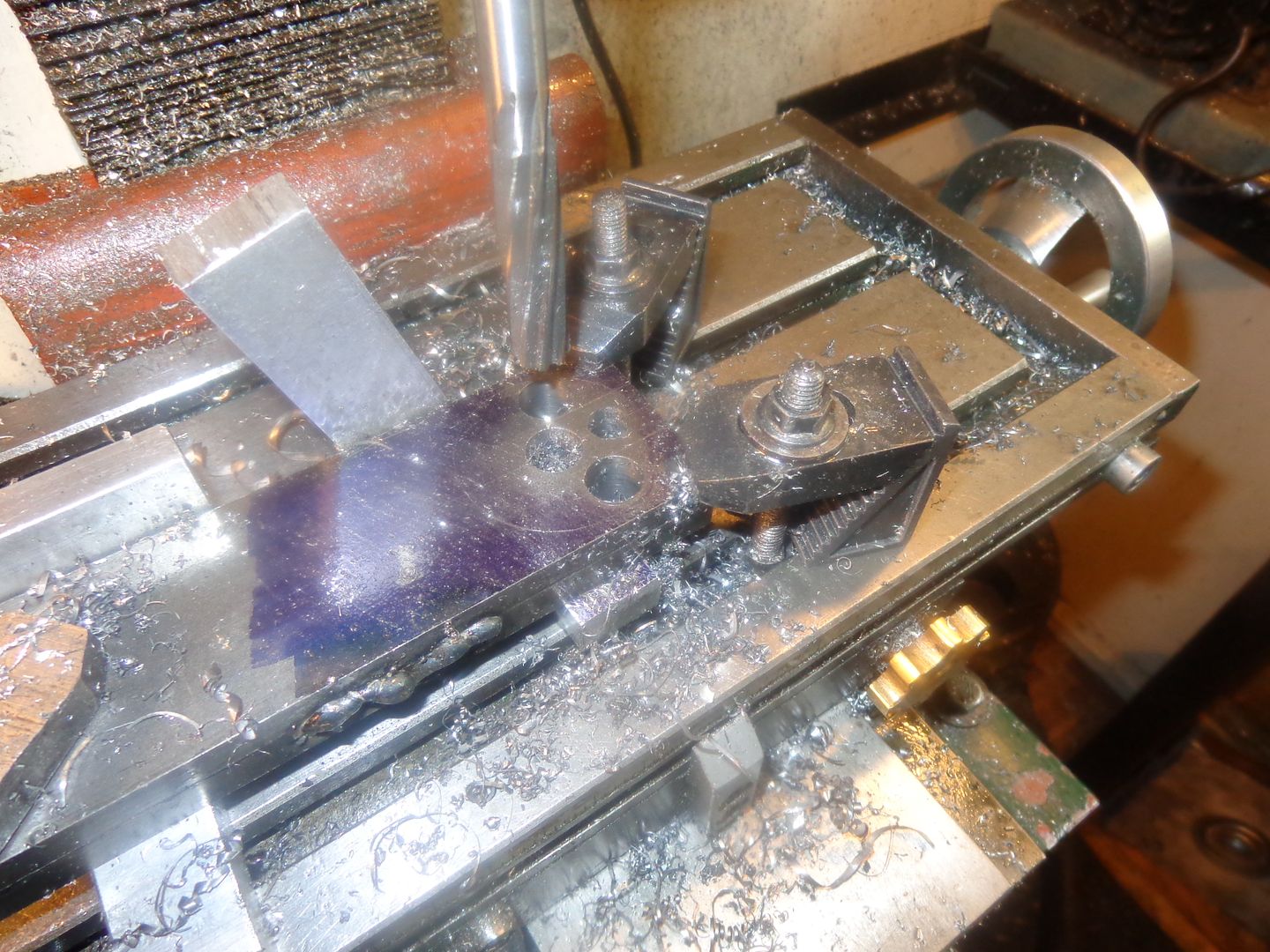
This type of crankshaft, where only one half bears the load from the connecting rod, and the other half simply follows the arc of the first half to drive the ignition points is something entirely new to me. I think that as suggested, the entire crankshaft will be press fit together with no pins or welds. I have found by experimentation that a .002" interference gives a really hard press fit, as hard a fit as I am capable of achieving with my equipment. The only "slip fit" will be where the con rod journal enters the web of the "follower half" of the crankshaft. The con rod journal itself will be hardened to 50-55 Rockwell c so the con rod needle bearings running directly on it will not chew up the surface. In order to get the holes in exactly the same locations in both crankshaft webs, I plan on mig welding the two bars from which the webs will be cut together, then drilling and reaming the holes with undersize reamers while they are clamped to the milling machine table with toe clamps (with a 1/2" piece of sacrificial aluminum between them and the mill table) to ensure that the axis of the holes are 100% square to the face of the bars. I don't trust my vice for this rather critical operation. I will have the thinner of the two bars, which forms the web of the follower crankshaft on top of the stack, so that I can run the undersize rod journal reamer thru both bars, then without changing my set-up run the clearance reamer thru the topmost bar only.--(Picture to follow). I think that in order to ensure that the pushed in shaft sets square to the plates, I will push the shafts thru the flatbar about 1/2", then trim the excess shaft sticking out the far side with my lathe.
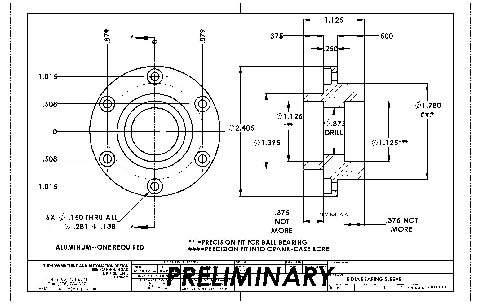
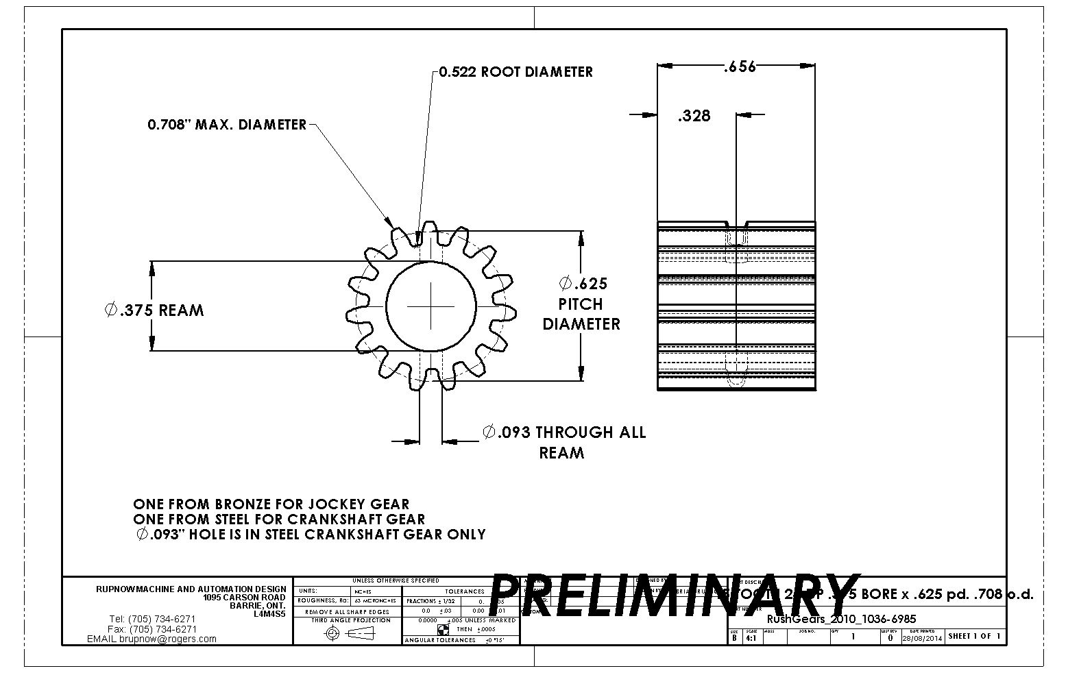
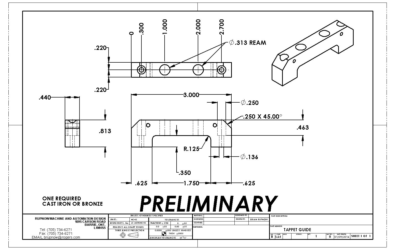
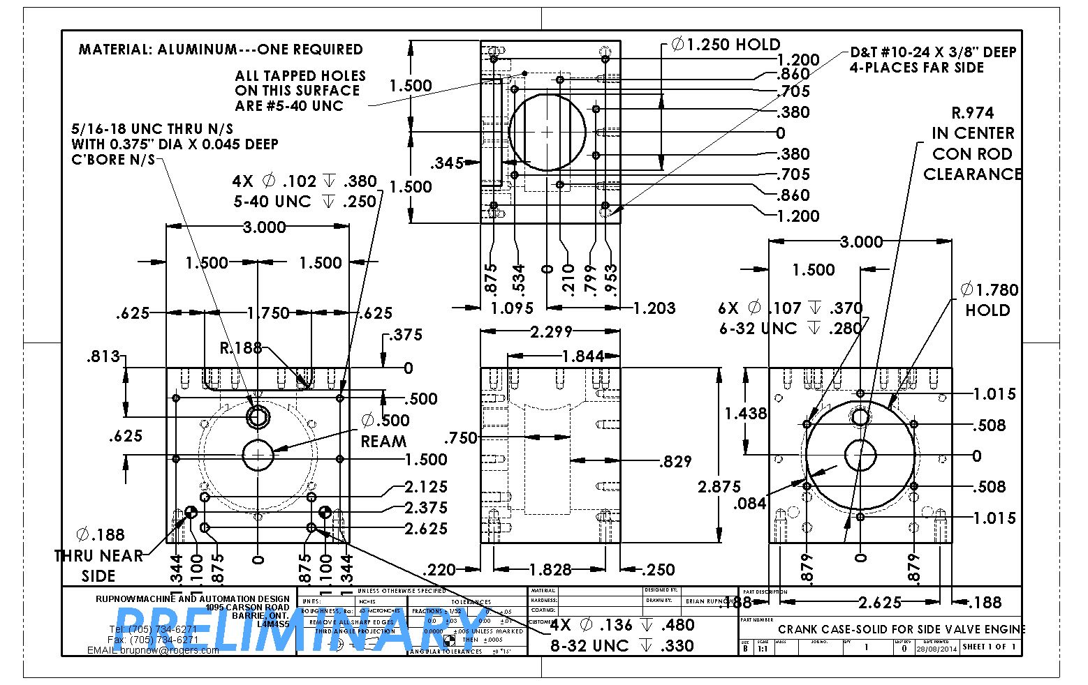
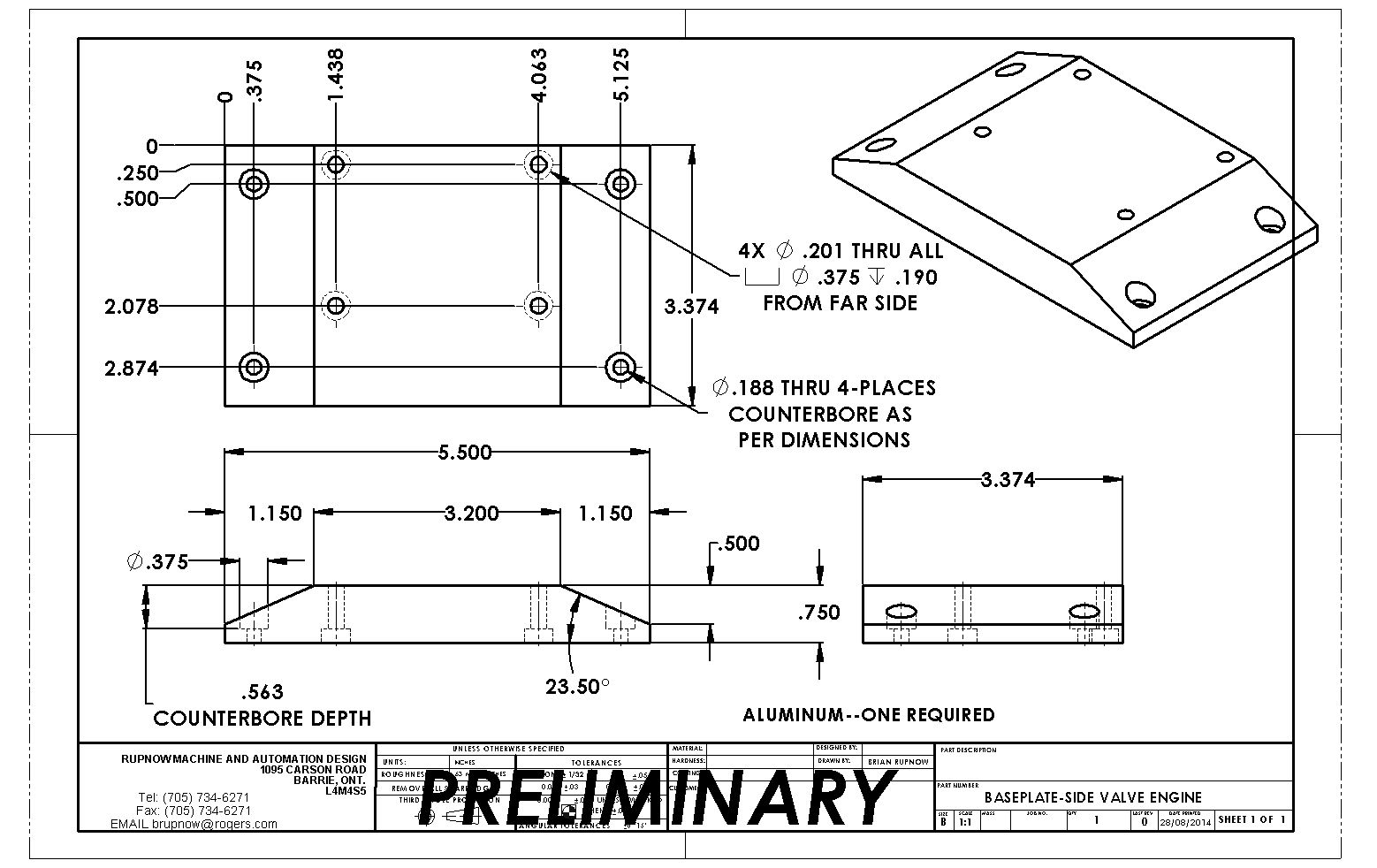
I seem to get more reactions to my posts when I post the actual in progress drawings of the pieces I am making even though these drawings may change somewhat as the pieces are actually made. For that reason I am going to post the drawings marked as "preliminary" purely for interest sake for the remainder of this project. I do not recommend that anyone save these drawings, but instead wait until the end of the project when I will post a download link to all of the corrected drawings.--I will begin by posting drawings of the parts which have already been made.-Brian


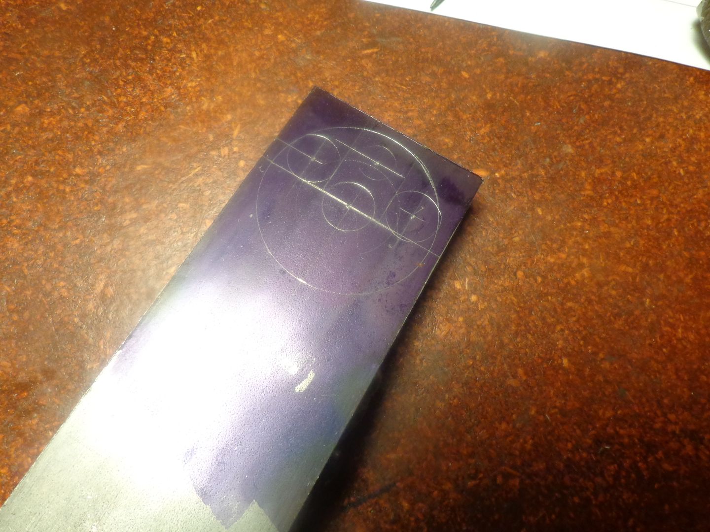
Here you can see my crankshaft web layout on one of the cold rolled steel bars. (There is one extra arc on there that shouldn't be---I had the compass set wrong) I won't be machining from that layout. It is only a visual reference. I will use the edge finder and the dials on the mill table to locate and drill/ream all the holes. You can also see a short bit of mig weld holding the two bars together. There is another weld the same size on the far side. I will drill both bars at the same time, then separate them and trim them, then press them onto their respective shafts and finish the o.d. in the lathe. It will be an interrupted cut, but i don't see any good way to avoid that.
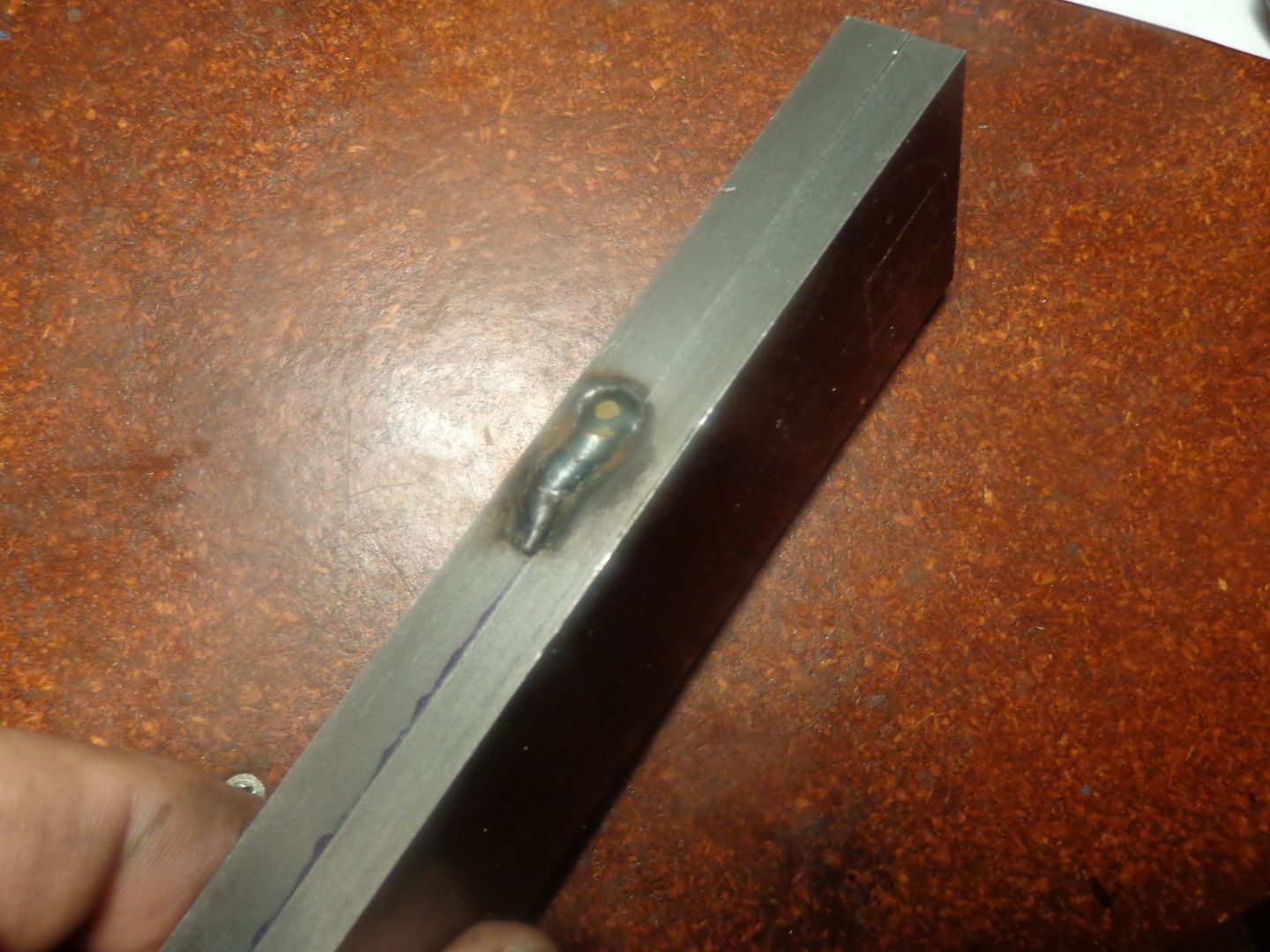


Hmmmmmmm---The best laid plans of mice and men----I reamed the holes in my web plates with my 0.4985" reamer. I then went to press the 5.0005 drill rod into place. It was su7pposed to be a .002" interference fit. It didn't exactly fall through, but it sure as heck didn't press. So much for my "all press fitted" crankshaft. That will now be amended to "My silver soldered crankshaft!!!"
Last edited:
Just as I was all set up to start silver soldering, my wife called about some emergency connected with the new house. Seems that 3 year old grandson had managed to lock and close a bunch of doors that there were apparently no keys to unlock!!!--After dashing across town and applying my dormant burglary skills (which mostly involved beating on the locksets with my 3 pound hammer till the guts all fell out of the locksets) I got to thinking-----I really didn't want to solder the crankshaft. I wanted it all pressed together. Then I got to thinking, I have a lot of 5/8" cold rolled shaft ends about 10" long that some kind soul from Toronto or Orangeville brought me a couple of years ago. The simplest thing in the world would be to turn new crankshaft ends (They are only about 3" long) and bump up the end diameter to whatever size will be a hard press fit in the holes I reamed in the webs. I THINK I know why the reamed holes are larger than they were supposed to be.---Hindsight being 20/20, I think I was running the reamer too fast and that made it cut oversize. I know that the drill rod I have just re-measured is exactly 0.500, not the .5005 that I was expecting it to be, and it is a somewhat loose sliding fit in the reamed holes. This leads me to believe that if I make up a new crankshaft end that is 0.500 diameter for all of its length except the last 3/8" which I hold at .503" diameter, I should ultimately end up with what I wanted---all press fitted together. The follower end will be turned to 3/8" over its full length, again, except for the last 5/16" where I will hold the 0.503" diameter. This is holding things to closer tolerances than I am used to working to, but it will give me what I wanted.
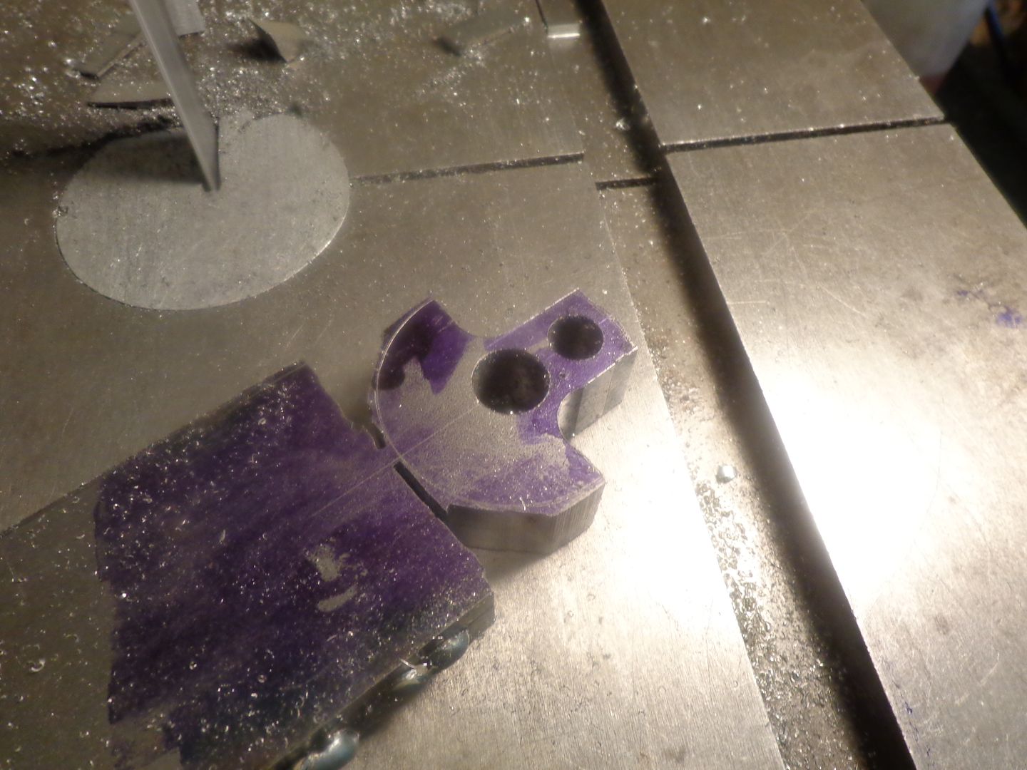
It has been a rather upside down afternoon for me, and in all the excitement I forgot to post a couple of "in process" shots of the crankshaft webs. The shot where the two bars are clamped on the milling machine bed show the shaft holes being drilled and reamed, and the holes drilled which will give the 1/4" radius in the inside corners. The second shot shows where the excess material has been milled away, and both parts are almost completely separated from the parent stock. The next step, if I ever get there, is to press the webs onto the crankshaft ends, set them up in the lathe, and turn the outer diameter of the plates to the finished dimension.


Last edited:
IT WORKED!!!!! 0.503" was just the ticket. It was all I could do with my big nasty old mechanics vice to bring the shaft all the way thru the web, and then with a hollow socket backing the web up, about 3/8" more. Then I set it up in the lathe, cut the stub end off that was sticking thru, and finish machined the outer diameter of the web. Tomorrow will do the same to the follower half of the crankshaft.


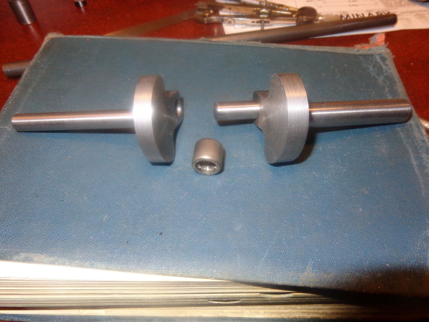
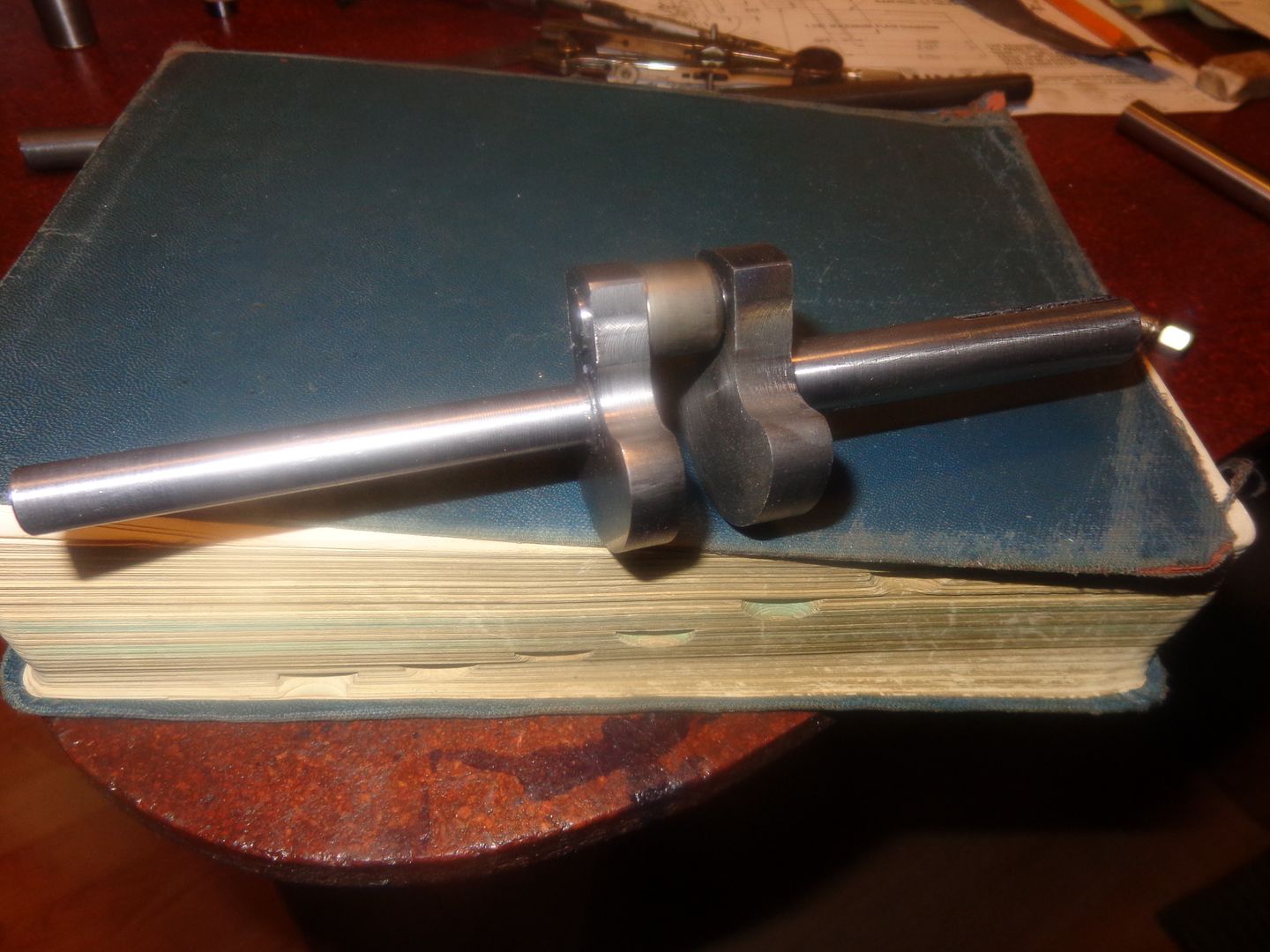
So--Ladies and Gentlemen--Here we have it!! My very first, two piece pressed together crankshaft. One picture shows the two pieces separated with the needle bearing for the big end of the con rod laying between them. The second picture shows the two piece crankshaft assembled with the needle roller bearing setting in its place. Each end of the crankshaft is supported by two bearings or bushings. The force from the con rod is totally transmitted through the 3/8" thick web plate to the large side of the crankshaft. The"free" end of the con rod journal engages with a slip fit hole in the other web and drives the smaller diameter side of the crankshaft, which operates the timing gears and the ignition points.


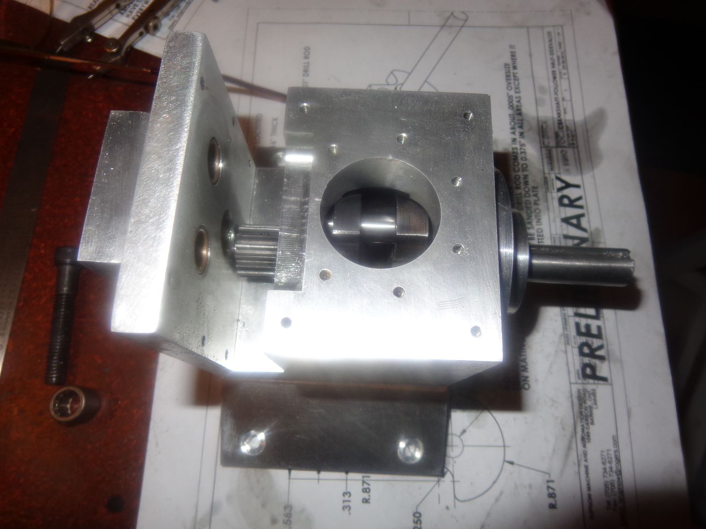
So, here's a view "Down the hole" as it were. The crankshaft fits in nicely, nothing rubs or scrapes when rotated through 360 degrees. There is one tight spot in the rotation, but it's only a minor tight spot which I'm sure will wear away once the engine is ran for a few minutes. There are supposed to be spacer rings incorporated into the crankshaft, just behind each web, but I'm going to wait until I have the cylinder, piston, and rod in place to determine their final thickness.

Similar threads
- Replies
- 95
- Views
- 12K
- Replies
- 22
- Views
- 2K


