A new engine for fall---

Home Model Engine Machinist Forum

Help Support Home Model Engine Machinist Forum:

This site may earn a commission from merchant affiliate links, including eBay, Amazon, and others.
Nice work Brian. Question on your SW drawings showing involute gear tooth form, do you have a trick to draw them for given size? Or downloaded accompanying 3D part from gear supplier or..?
 
No machining today. I did however work 8 hours in a design office across town, rush home, gobble supper, drive to new house, install 3 smoke/carbon monoxide detectors, put new locksets (without keyholes) on two doors, measured up the partially rotten deck for new planks as required, and remove one door and bring it home to trim the top so it will close properly and install a cat door. Now I'm going to drink my herbal tea and go to bed!!!
 
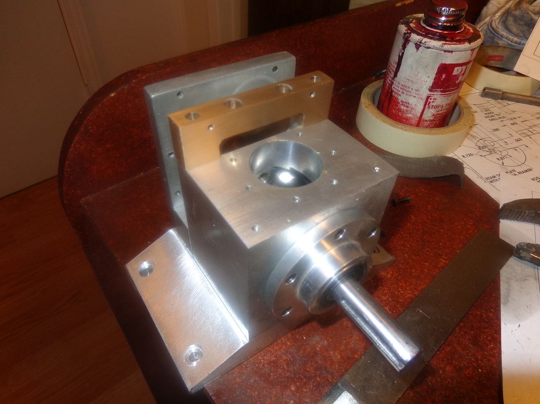
Had time for a "quicky" before I left the house this morning.---No, not that kind of "Quicky" ya dirty buggers!!! I finished and installed the tappet guide, in bronze. The corners aren't mitered yet, as I thought it best to bolt all the mating pieces together and miter them all at the same time so the corners line up nice.
 
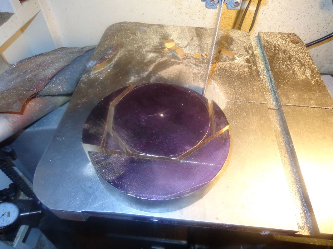
Making a 4" diameter flywheel from a 6" diameter slab of bronze x 1 3/8" thick may be cheap---(I got the bronze for nothing), but it sure isn't easy!!! That's a lot of cutting on my old "push as you go" 14" jet bandsaw!! I have a good center punch mark where I anchored one leg of the compass that drew the 4 1/8" circle, and I will use that center punch mark for setting up in my 4 jaw chuck in the lathe to turn the flywheel.
 
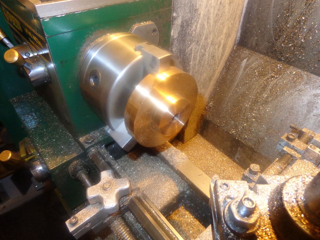
Slowly the flywheel is taking shape. I centered it in my lathe 4 jaw chuck around the center punch hole that I mentioned in a previous post, then turned most of the outer diameter (except the part held by the jaws) and drilled and reamed the center hole and the two large counterbores and faced the exposed side. My 3 jaw chuck will hold up to a 4 1/8" diameter piece with the reversed jaws in it, and the flywheel was now 4" diameter on the machined outer diameter, so I changed chucks, flipped the flywheel around, and carved away the material to leave the 2" diameter spigot as shown in the picture. I still have to take my evil trepanning tool and put the recessed annulus in the exposed side, and then add the 3 tapped holes to hold the starter ring and put in a keyway and set screws. I an very busy with other things right now, so I just do a bit of machining whenever I can fit it in.(And if I have any energy left!!!!)
 
It’s looking good Brian, I have my chair pulled up and the coffee on.
I see on the news Ontario was getting some “severe weather” again. Did you get any out your way?
 
bmac2---Thanks for stopping by and saying Hi. When I get to this stage of a build, and people don't have much to say, I always start to wonder if I'm posting in a vacuum and nobody is looking. I'm just getting to the exciting part now. Next up will be the two piece cylinder.-- We had a really vicious rainstorm here for about 20 minutes, but no damage at my place. We had a few tornados touch down in nearby areas, but once you get out of the towns here, there isn't much but bush, so the only homes lost belonged to the bears and the deer.-Brian
 
Cowabunga!!! I like that!! And that is the last easy part finished for a while. I want to see what this thing looks like with a cylinder on it.
 
I just had to share this, because I know all you old grandpa types like me will love it. This shot was taken last week as the girls were heading back to school for 2014. Brennen is too young for school, but he wanted to be in the picture. Wife and I just got back from our first "overnighter" with all 3 grandkids. Drove 185 Km up to Bancroft to see my 94 year old mother and wish her a happy birthday. There is always a certain amount of trepidation when taking a grandkid away overnight for his/her very first time, but Brennen was a trooper and probably slept better than I did. "Little Grandma" was happy to see Bren, as the last time she seen him he was a new born.
 
bmac2---Thanks for stopping by and saying Hi. When I get to this stage of a build, and people don't have much to say, I always start to wonder if I'm posting in a vacuum and nobody is looking. I'm just getting to the exciting part now. Next up will be the two piece cylinder.-- We had a really vicious rainstorm here for about 20 minutes, but no damage at my place. We had a few tornados touch down in nearby areas, but once you get out of the towns here, there isn't much but bush, so the only homes lost belonged to the bears and the deer.-Brian

Something I saw on an RC forum.
"Don't judge a build thread by its replies but its view count"

If the views keep going up then there are clearly folk interested
 
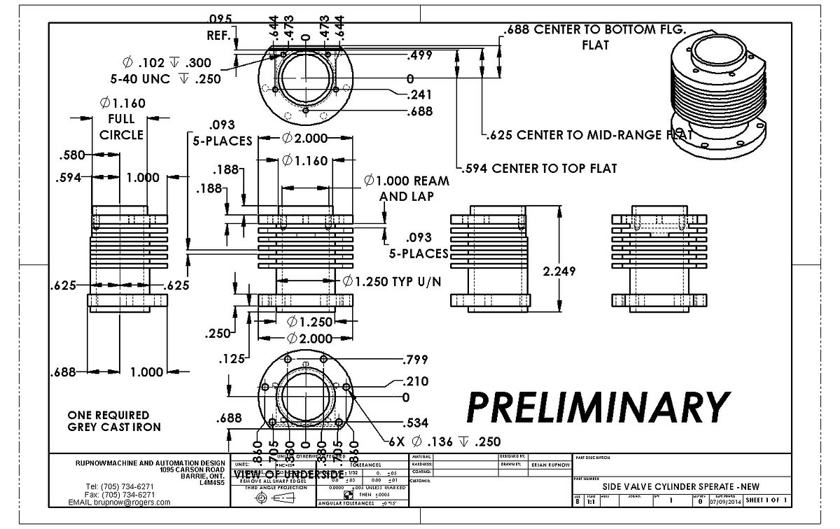
This is going to be---well--tricky. There is no great science in the cylinder itself, other than having to hold my breath for minutes at a time while I plunge cut the 3/8" deep grooves with my .093" wide HSS parting off tool. The tricky bit will be in machining the three different levels of "flat" without breaking any fins in the process. I am told not to use cutting fluid when machining cast iron. Any good advice would be well appreciated before I get too deeply into this.---Brian
 
Brian, I always stayed away from cutting fluids when machining cast iron, apart from some tapping oil when threading holes. I think that it may be something to do with the way cast iron machines into grains, it would get a bit messy with coolant, possibly turning into a lapping paste. CNC machining with high pressure coolant is probably ok

Paul.
 
Paul--As I understand it, grey pearlitic cast iron has a high graphite content, and as a consequence it is self lubricating. That is why it is popular for use in engine blocks and cylinder liners. Of course, this explains why you don't NEED coolant/lubrication when machining it, but it doesn't explain WHY you shouldn't use lubrication/coolant when machining it. I just googled it, and the Sandvic website confirmed what I thought about not needing lubricant, but it didn't say anything about not being supposed to use lubricant. On a deep plunge cut like the fins require, I would think that the use of lubricant would help flush out chips and keep the tool from grabbing and/or binding, but I don't know for sure.
 
Maybe another problem with cast iron and coolant is that it may "soak" up some coolant due to the grain structure.

Paul.
 
I just did a bit more internet searching on why NOT to use cutting fluid/lubricant with cast iron. Someone who writes machining articles has said that using coolant when machining cast iron causes localized hard spots in the cast iron. I'm not sure I really believe that but ---Hey---I seen it on the internet!!--It must be true!!!!
Edit---The book was Milling by Stan Bray and to quote 'the one rule to remember above all when machining it (CI) is not to use cutting lubricants; their use will cause the area around the machining to become so hard that it is no longer possible to work on it.'
 
Last edited:
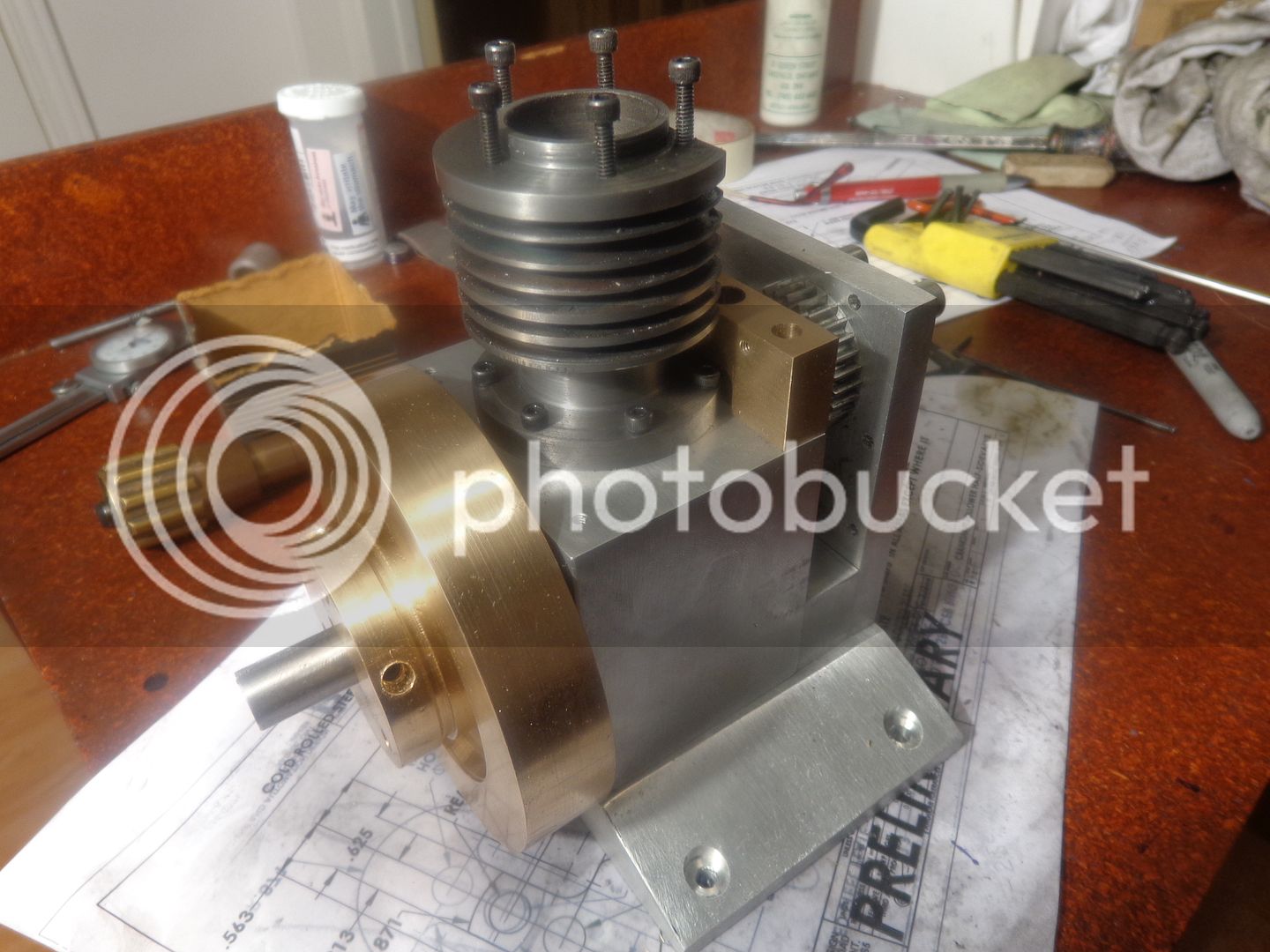
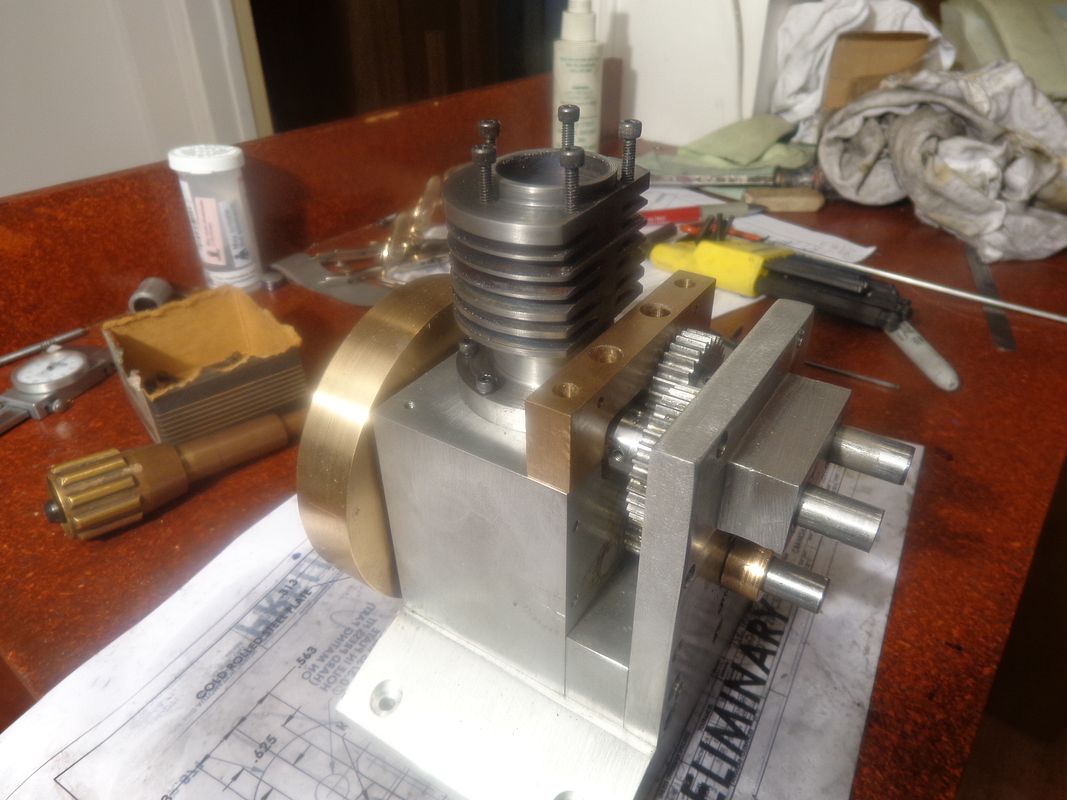
Made a mistake. Kissed a snake. How many cooling fins did I make??--Well okay, maybe you're not into skipping rhymes!!! However, if you are paying attention, you will see that I have one more cooling fin on there than the drawing calls for. To make it even worse, the top 3 cooling fins are skinny little devils, while the bottom 3 are full size. I have absolutely no excuse for it, other than encroaching old age and gross incompetence. By the time I noticed that the first cooling fin down from the top was too skinny, I had already advanced the tool .040" into the work, and there was no good way to hide it or cover it up. I'm still a bit baffled as to exactly what happened, but somewhere in there, the math let me down. At any rate, I have convinced myself that since this is a prototype, it really doesn't matter that much. The cylinder will still function just as well with one extra cooling fin. Everything seems to bolt together okay, although I did have to use a ball end hex wrench to tighten up the bolts holding the cylinder to the crankcase.---Probably would have had to do that even without the extra cooling fin. And for my next amazing stunt---I will be making the combustion chamber that mounts on top of the cylinder.---And, Oh yeah---I machined the cylinder dry, and there was absolutely no binding, galling, or ``scare the crap out of me cut off tool breaking.

 
Last edited:
This is the part I will build next. I will probably mess with the cooling fin spacing a bit so it matches my miss-machined cylinder cooling fins.
 
Call it a design feature, Brian. Maybe it needs different cooling nearer the head?:rolleyes:

Ian.
 
Don't beat yourself up too much Brian, it certainly still looks OK. If you hadn't mentioned it, no one may have noticed.

Paul.
 

Latest posts

Back
Top