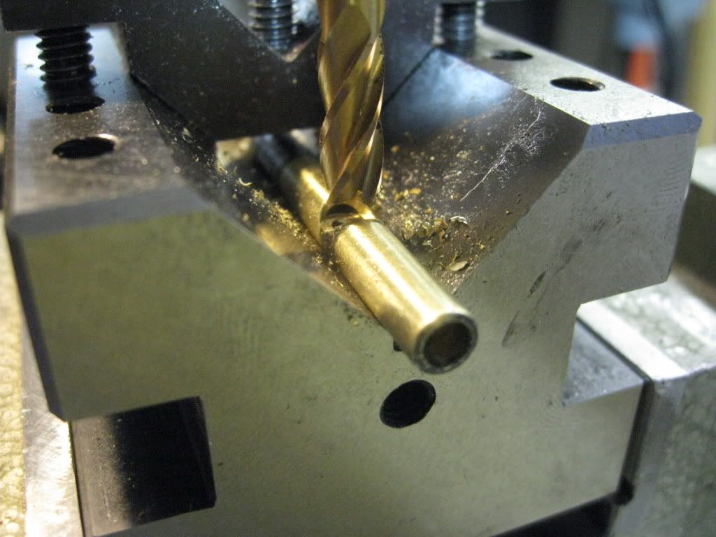
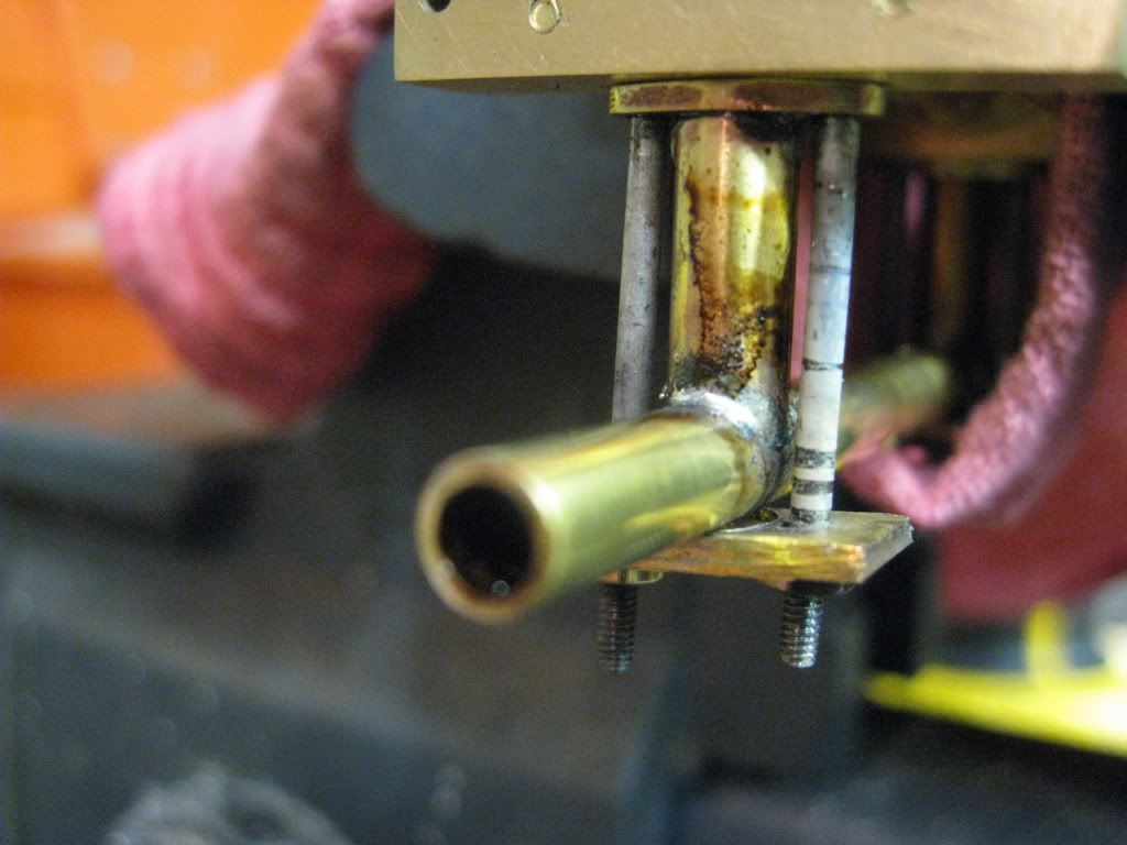
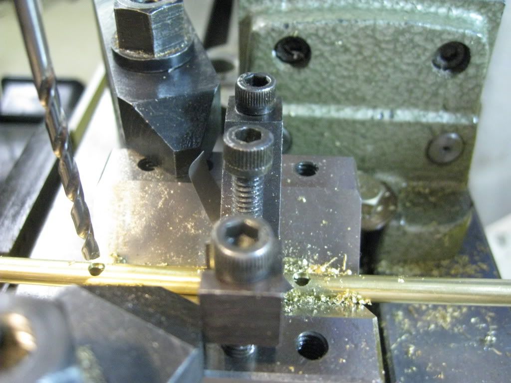
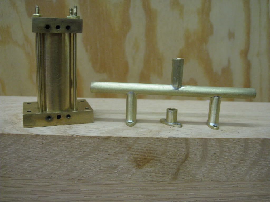
Things are looking up. I machined up another cylinder for the piston valve assembly. Per Arnold's suggestion I attacked this from a different direction. Rather than machining sockets in the "cylinder", I used a 1/4" end mill to cope the end of the standoffs.
I drilled the mating holes in the Cylinder of the piston valve assembly.
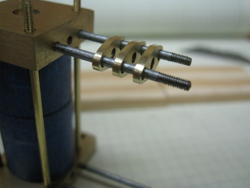
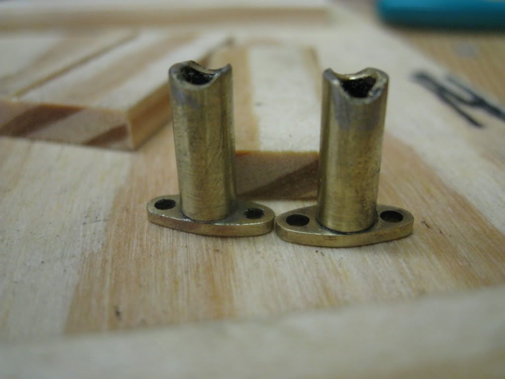
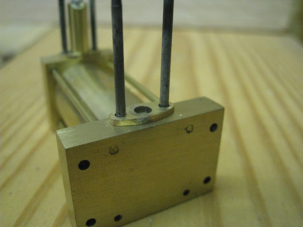
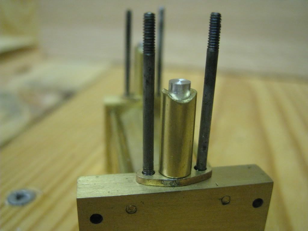
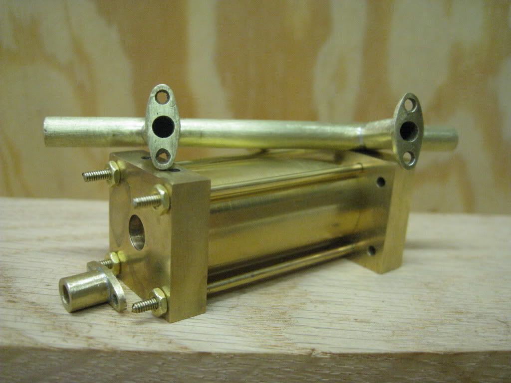
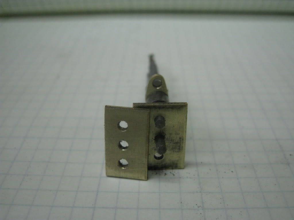
Building the assembly this way caused me to scratch my head in determining the correct sequence so everything would be aligned correctly. The coped ends had to be clocked to the flanges so it would all bolt together correctly. Here you can see the flanges on the base of the power cylinder.
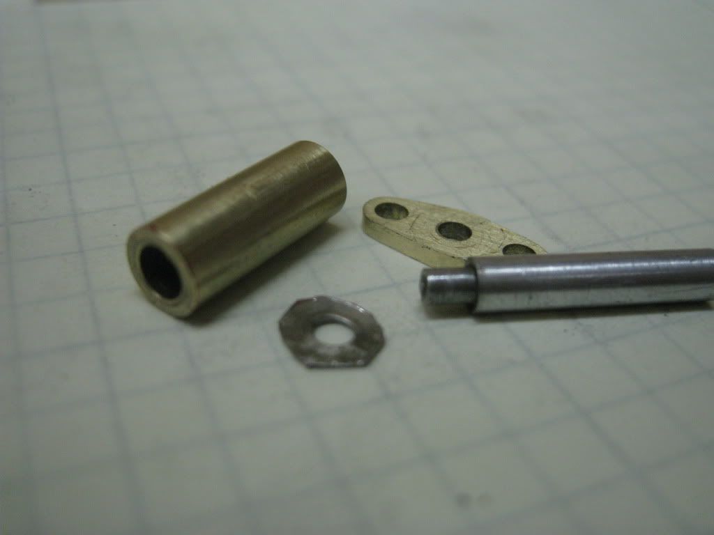
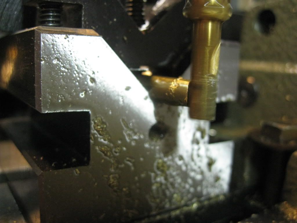
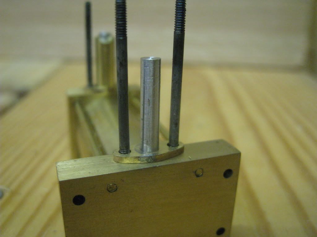
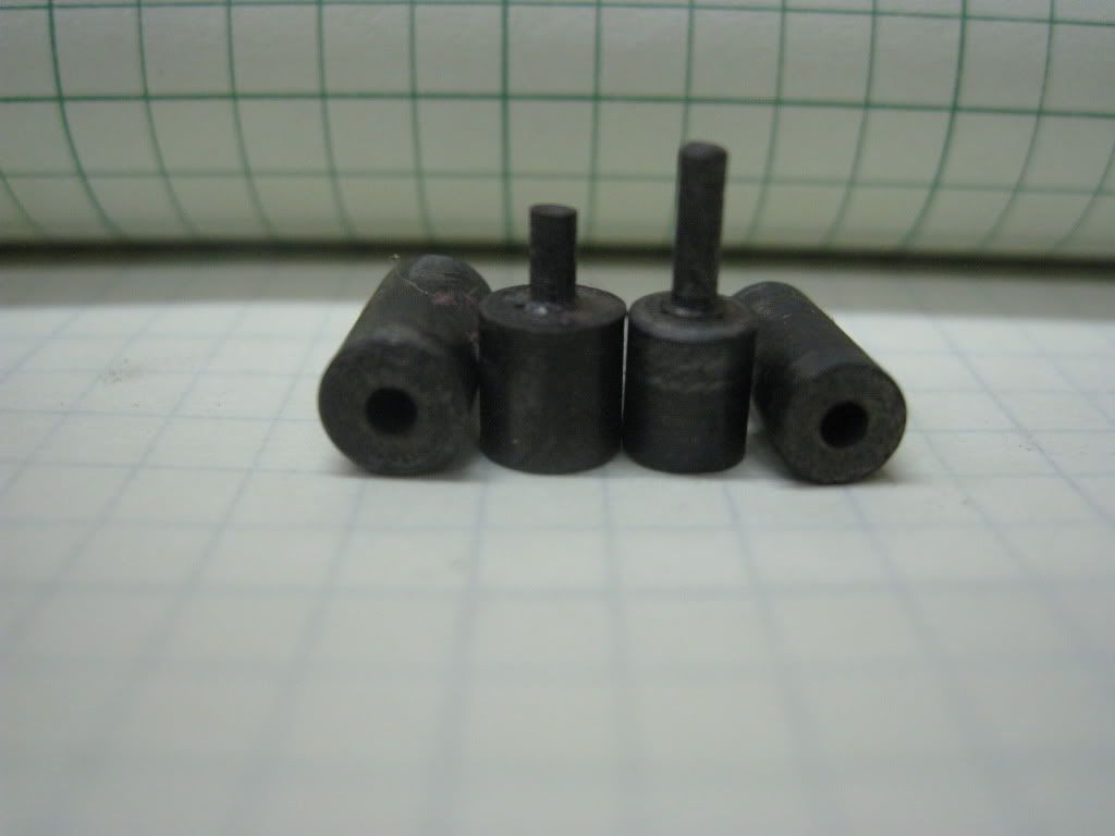
I made a locating dowel out of AL because the solder wont stick to it. Sometimes I thought that solder wouldnt stick to the brass either.
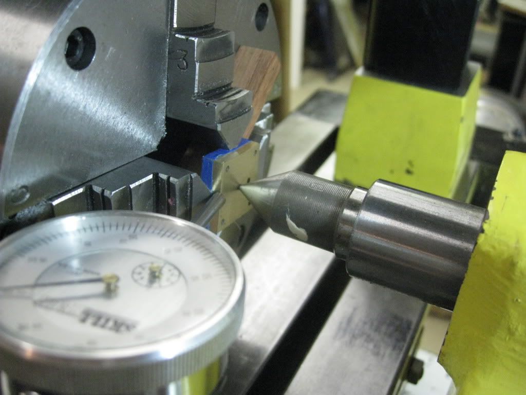
You can see the coped end of the standoff in this picture.
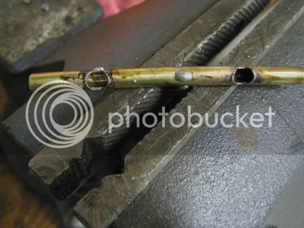
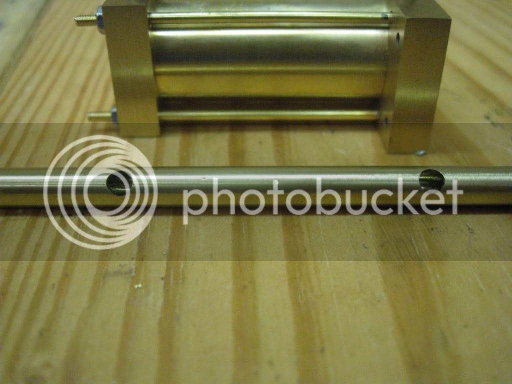
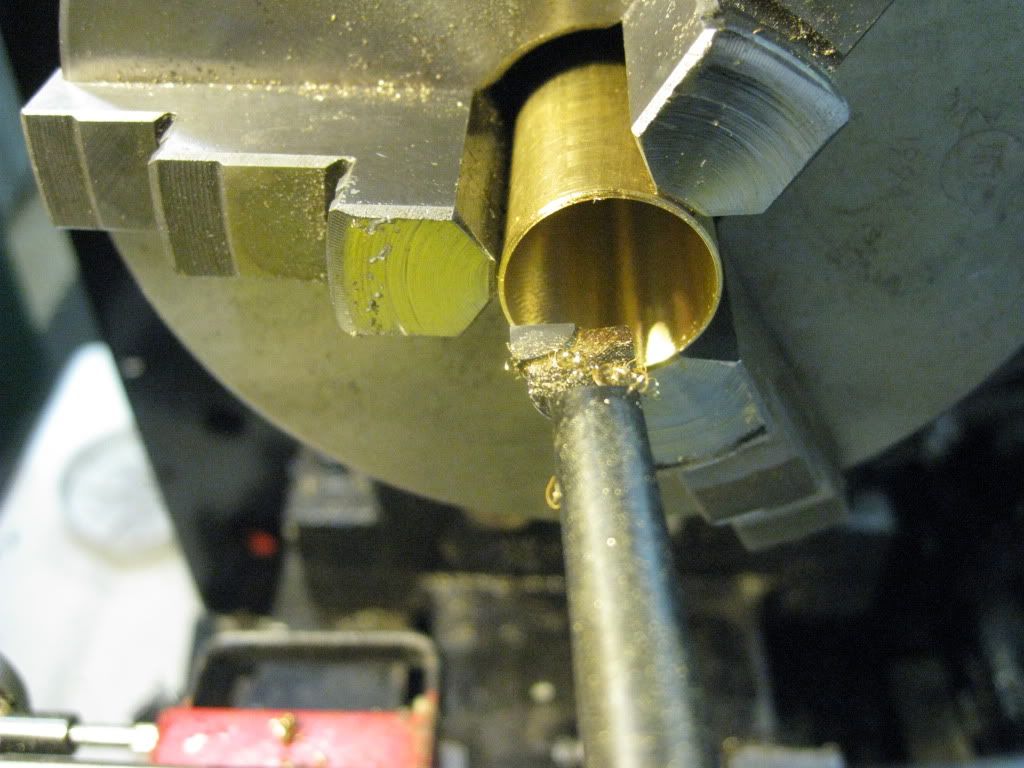
This piece of tubing is the cylinder for the piston valve assembly. The holes will align with the hole going through the standoffs.
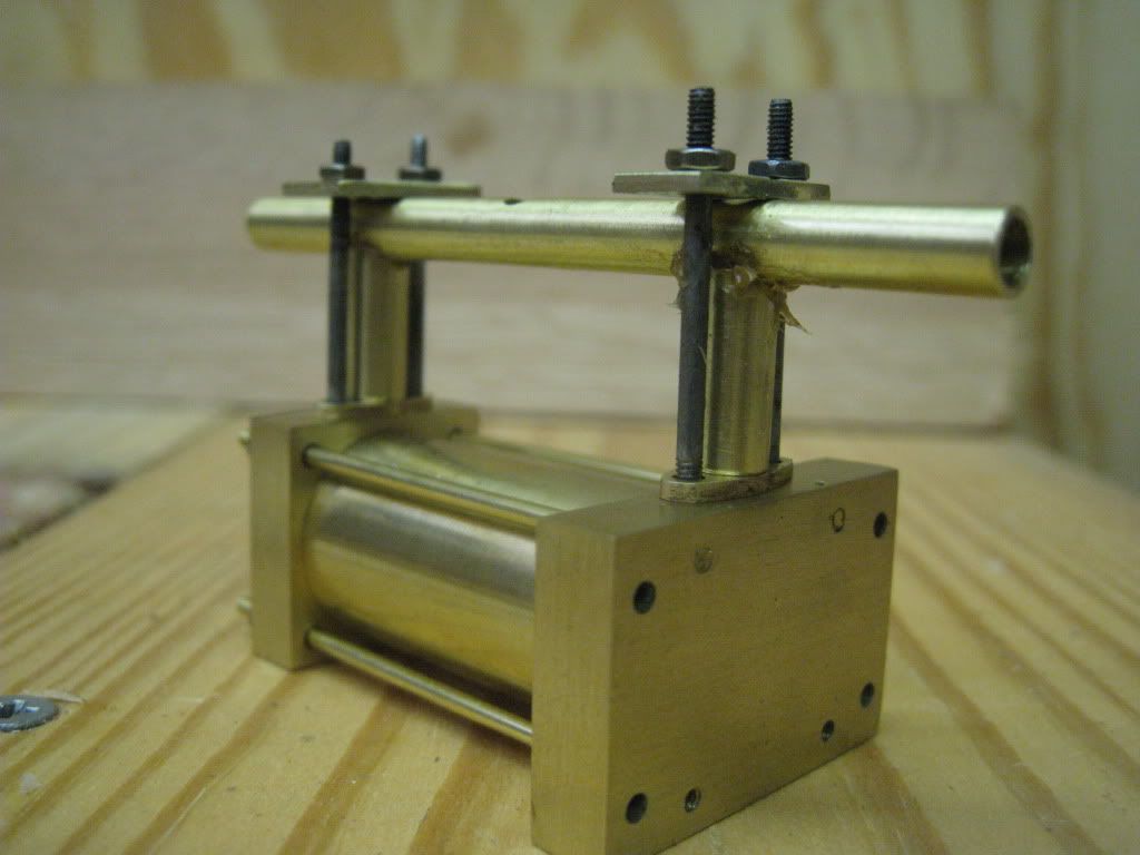
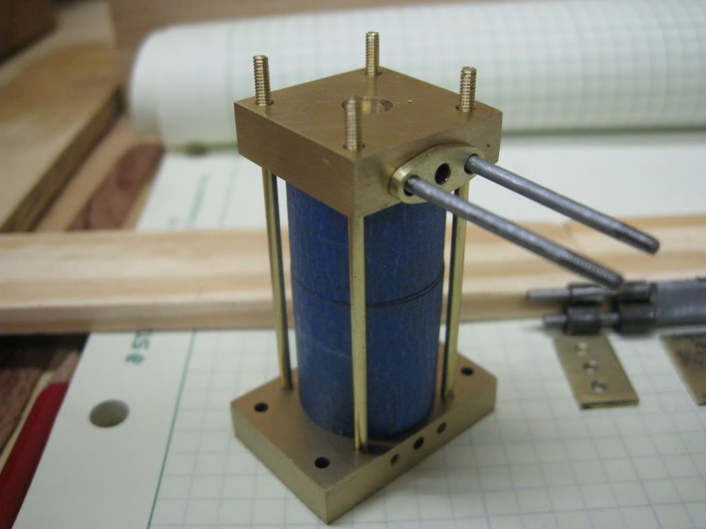
All of the parts of this assembly are ready to be soldered. Note the strong backs I used to hold it all together. All of the joints have been fluxed and I hammer forged washers of silver solder that are sandwiched between the joints.
Hold on
..
How on earth are you going to get the AL alignment dowels out once this is all soldered up?
Im glad you asked, in fact I am more glad that I asked.
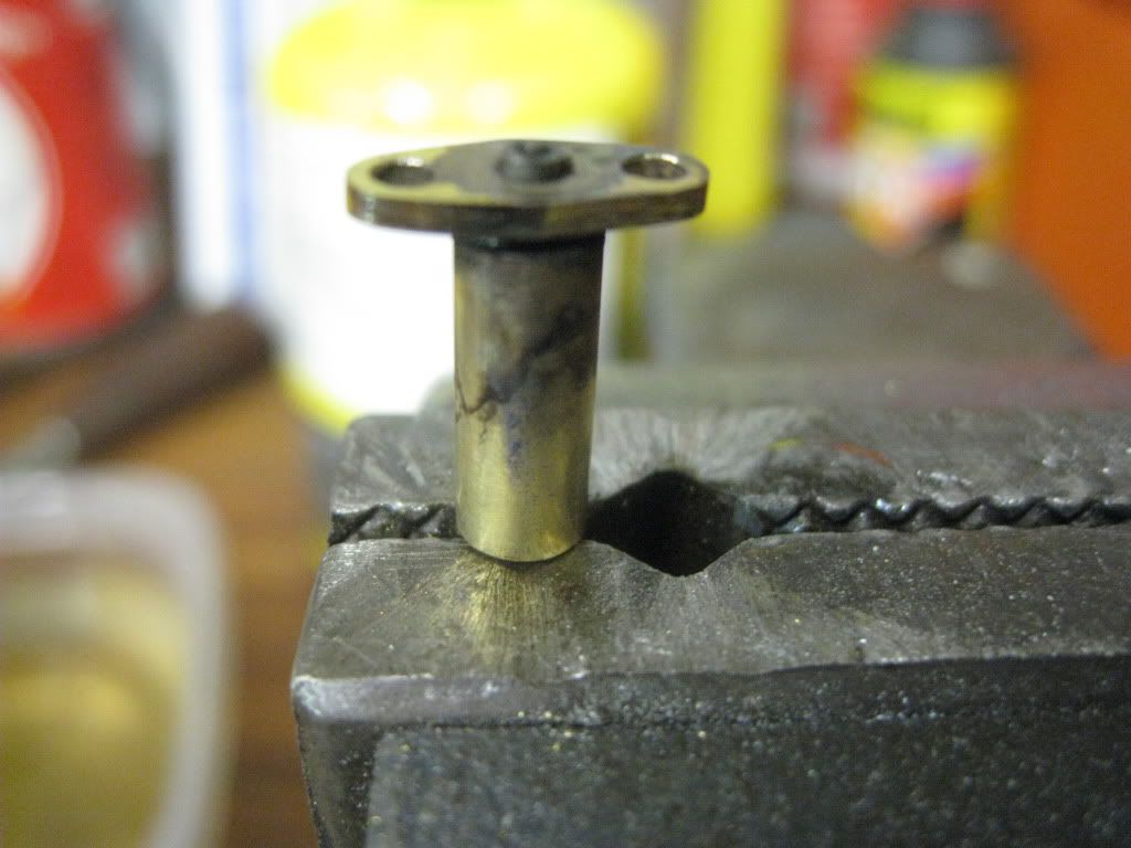
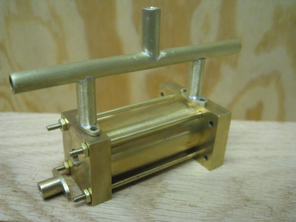
I tapped the dowel 4-40 on the flange end. Once everything cooled down, I unbolted the assembly and pulled the dowels out.
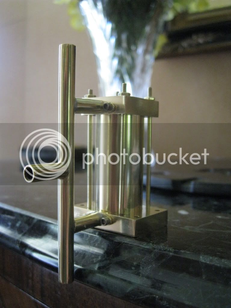
Here is the assembly.
Now I must confess, it didnt look like this when I finished soldering it. There is a couple of hours worth of file time and sanding. Im not sure if this is the finished version or not.
I know I left something out, I will think of it later.
Thanks for stopping by to visit.
SAM
I remembered what I wanted to say.
I still have to ream the bore to 3/16". Once that is done, I can consider this piece finished.


 The wood and brass combo is looking good. Thanks for posting.


![DreamPlan Home Design and Landscaping Software Free for Windows [PC Download]](https://m.media-amazon.com/images/I/51kvZH2dVLL._SL500_.jpg)