Werowance builds a webster

Home Model Engine Machinist Forum

Help Support Home Model Engine Machinist Forum:

This site may earn a commission from merchant affiliate links, including eBay, Amazon, and others.
Thanks Mechnicboy, here is what I took from that, copy and pated below


General Principles


There are three basic principles in spring design:

· The heavier the wire, the stronger the spring.

· The smaller the coil, the stronger the spring.

· The more active coils, the less load you will have to apply in order to get it to


move a certain distance.
 
Werowance--I'm not certain where you are, but if you are near or in any mid size city, there will be two or three industrial fastener outlets that have selections of compression springs at a very reasonable price. I buy them from Brafasco, or Fastenall, or Bolts Plus here in Barrie. The springs cost from $3 to $5 each, and can be bought individually. You will need springs with an inside diameter of at least 3/16" to fit over your valve guides. Don't even think about using the same diameter spring wire for both exhaust and intake valves. There is enough heartache involved in starting a new engine without making your own problems. Try and match the wire diameter given in the Webster plans.---Brian
 
re post #177, on building a Webster: I have had the best results using a single flute counter sink, but can still produce chatter. Better parts can be produced, especially if using a drill press, by letting the part float on top of the vice i.e. the part will be caught from rotating by the edge of vise jaw. Slow the rpm's down, even to the point of pulling a lathe or drill chuck through by hand.
Carlos
 
Thanks Brian and Carl, Brian on the springs I think I have come up with a workable combination. the exhaust spring is larger in guage of wire and size and is stiff. the intake is smaller dia and gauge and a little shorter to. its pretty soft. if it doesn't work out I will have to recut my keepers. now on the note of keepers I changed the design just a bit. I recessed the area where the cross pin would sit so that it will retain it. but the overall working length will still be the same, just brought up the side so it would hold the pin in place. now on the cross drill of the valves. I have had a time with that. my vblock with the clamp wont clear my chuck for the #60 drill to cross drill it. what I ended up doing and it worked very well was to put a drop of lock tight on it while in the vblock and left it clamped over night to dry. then removed the clamp and the valve held in place just fine for the cross drill. most of the lock tight chipped away with my finger nails then from the tip (where a rocker arm would hit) I lightly tapped it just like a rocker arm would tap it and it came right out. was concerned about deforming it but it didn't take any work at all to remove it and all came out well. have to get started on the other one tonight.
man that little .040 hole is tiny, I cant even focus my eyes on it.
upload_2019-8-7_10-56-36.png

upload_2019-8-7_10-57-0.png


upload_2019-8-7_10-57-37.png
 
I generally drill that small cross hole while the "handle" is still on the valve. Put the "handle between the vice jaws with the end of the valve sticking out past the jaws. Then I use my electronic edge finder to position the mill quill exactly where I want it to be, use a very small center drill to start the hole, then drill it. If you look over on my "vertical hit and miss" thread you will see a solution I came up with to hold the valve after the handle had been cut off.---Brian
 
very good idea, and I do remember seeing how you held the stock with sort of a busing with a slit in the side which was a very good idea. wish I had thought of that before hand. especially drilling it before parting off the rest of the stock.
 
had a semi productive weekend. finished up the valve blocks, cross drill of the last valve almost ended in disaster, bit broke right as it broke through the other side. fortunately it broke through enough so that I could push it back out the way it came. then since I had a broken bit, I used the shaft as the cross pin for both valves. so it still had a purpose. then I cut and sized all the bushings and washers needed to align everything then assembled almost the whole engine. things left to do - lap cylinder, make muffler and carb adapter, put together ignition and then time the engine. I need to re-read on how others pinned or set screwed the fly wheel and set timing as well as how the muffler and carb adapter were held in place - either press fit or lock tight etc...

here are some pics of the valve block first one with broken tip drill bit

upload_2019-8-12_9-23-13.png


upload_2019-8-12_9-23-40.png


upload_2019-8-12_9-24-10.png
 
Here's a hint. Put gaskets between those three individual pieces or you're going to go crazy figuring out why your engine won't run. Find a thin gasket material, A cornflakes box is .022" thick, and it works. You can't use any liquid goop as a gasket because it squeezes out and screws up your valves.
 
I have been doing some reading on how to cam time this thing and its 15deg Bbdc. and on top of that the fly wheel gets cross pinned with roll pins on both sides. also re-read Brians build and he used a long reach drill to do that. - I have one on order, and I already have some long reach center drills. but on that note, I really really dread this part of it. just makes me nervous about getting the timing just right so I'm asking about experience with set screws on the fly wheel. first of all my fly wheel is very tight on the shaft to begin with. I made a dbit reamer from left over shaft material that I used emory cloth on to make it even slightly smaller than the actual shaft so as to obtain a very tight fit of the actual crankshaft. this way no woblly loose fitting fly wheel. yes I know tight is not enough to hold up to the forces of ignition hammering on it but I was thinking about set screws instead of a roll pin. thus allowing me to adjust timing if I need.

I was thinking of a cup style tip set screw. 2 on opposite sides / on both sides of the fly wheel = qty of 4 total.
if not cup what about point? below are pictures of the 2 styles I had in mind. if not permenant what about just long enough to get it running then switch to roll pin?

upload_2019-8-12_10-50-2.png
 
Don't do it. Time your engine as close as you can get it, then drill and cross-pin like the instructions say. If you are out, you can change the meshing of the timing gears to correct the timing.
 
There are 24 teeth on the crankshaft gear. There are 360 degrees in a circle. 360 / 24=15 degrees in each tooth. I had much the same concerns as you about getting the hole in the correct position. I built a jig to ensure that things were in the correct rotational alignment before I drilled the crankshaft. I will try and find my original build and see if the jig drawing is shown there. See post #267 (or close to that) and you will see the fixture I made to position things correctly before drilling the hole in the crankshaft.
https://www.homemodelenginemachinist.com/threads/anybody-want-to-guess.7687/page-14
 
Last edited:
Werowance--I still have that fixture I made to time the Webster around here somewhere. If you want it I can send it to you. If you want it send me your address and I will put it in the mail tomorrow.---Brian
 
That is a really kind offer. let me re-read your build and look at the fixture. my concern is where I deviated from the plans on the crank a bit to accommodate ball bearings as well as a counter weight it may not work.
 
last night I decided to try out an ignition circuit. the ford van coil pack either does not work or I wired it wrong. ill pick up a regular 12v coil from tractor supply in the next day or so. same as I use on my farmall. I know exactly the setup for it and the terminals are labeled + and - so I don't mix them up. the ford van coil pack or coil over plug as I learned they are called did not work. that was a gamble and I wanted to try it for size reasons but it didn't pan out for me.
 
Brian, i was looking back at your thread and how you used that jig to set the timing and drill. i see that the basic of it is that you have a hole drilled at a certain height that your crank throw pin fits through to hold it in position. then an area to clamp your fly wheel when you have it set right. i believe my fly wheel will hold itself in position just fine because its extremely tight already. perhaps a drop of lock tight at the edge of flywheel/shaft for good measure before drilling.

but my question is, how did you calculate the height of the hole in the jig for the crank throw pin to obtain the 15 degrees? i was considring jsut using my angle blocks to find it but im betting you used some sort of math to do it and id like to learn it. kind of like how you amazed me yesterday with the simple solution to calculate 1 gear tooth = 15 degrees, that was so simple but i would have never figured it out.
 
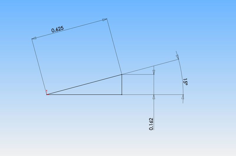
Werowance--it's simple trigonometry. The crank arm on your engine is 5/8". You want it to be rotated "up" at an angle of 15 degrees counterclockwise from horizontal. So--- .625" x sin 15=.162" see the diagram.
R6djPH.jpg
 
Thank you Brian! fyi I failed 2 years of pre-algebra. I can count to 10 on my fingers and 20 if I use my toes as well. lol. and now I see how you did that which is a great and very usefull lesson for future projects. also without the diagram I would have never ever understood what you were talking about so that extra effort is very much appreciated.

basicly drill a hole whose center is .162 up from the bottom of a good square block that fits my crank pin and put the nut on the pin to hold it in place and make sure the block is clamped down to the engine base and that should give me the 15 deg needed. this will take away a lot of my fear on timing this thing.

edit, just tried this on the windows calculator using the sin button and got .16176.... so I guess normally you would round up or down to the nearest thou?
 

Latest posts

Back
Top