Water Gauges for Boilers.

Home Model Engine Machinist Forum

Help Support Home Model Engine Machinist Forum:

This site may earn a commission from merchant affiliate links, including eBay, Amazon, and others.

Tony Bird

Senior Member
Joined
Feb 20, 2011
Messages
825
Reaction score
901
Location
Cardiff, South Wales, UK
Hi,

Some Thoughts on the Design & Construction of a Small Water Gauge suitable for Model Steam Boilers.

I have made many small steam boilers and usually make the fittings for them as well. Boiler fittings usually look better if they are small, there is a limit to how small of course, they have to work. Designing and making boiler water gauges over the years I have decided on several factors that effect how well they work.

Use the largest diameter glass tube you can, I have found that a tube 4mm OD with an ID of 2.5mm is about as small as you can hope to work. Also the minimum size of the water/steam holes in the fittings should be the same size or larger than the ID of the glass tube. Another factor to be considered is the ease of cleaning the gauge glass. The glass itself can usually be cleaned by removing the nut on the top fitting and pushing a pipe cleaner (tobacco type pipe) down into the tube. It is also a good idea to be able to clean out any mineral deposits that accumulate in the bottom fitting without having to remove it from the boiler. Good boiler hygiene can reduce this mineral deposit problem even if like me you live in a soft water area and mostly use rainwater in your boilers. If the boiler is used frequently like the one I use for testing models it is a good idea to completely fill the boiler with a mild acid such as citric or white vinegar about once a year. Leave the acid in the boiler for a few hours say over night then after emptying the acid flush well with clean water. Doing this will remove a lot of the deposits that might be in the boiler. If the boiler isn’t used much it is a good idea to drain the water from it after use.

With small boilers it is often difficult to make the water gauge short enough so there is enough visible length left on the glass tube to see a reasonable length of water usage.

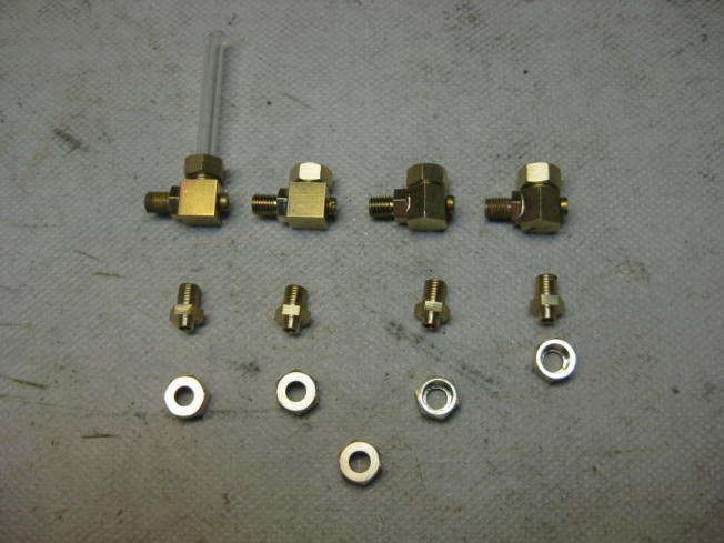
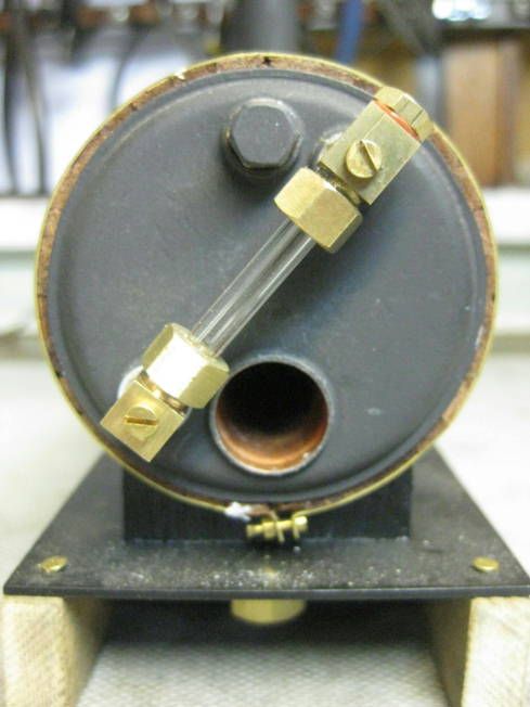
The design following tries to keep the height of the fittings as small as practical and its design is based on previously made gauges. First a couple of photographs of some gauges already made. They are basically of the same type.

One made using round stock for the bodies
.
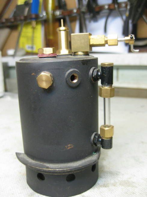

One made from round stock fitted with a blow down valve. Note the glass tubes which are half white with various lines running down them are often slightly over size and out of round. They are also a little more difficult to cut.
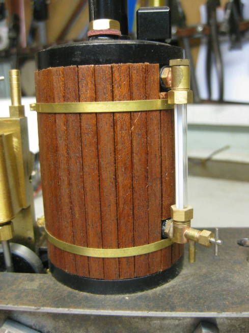


One made from hexagonal stock.
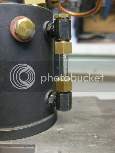


The one that the one to be described is based on this one which is made from 7mm square stock which had to be machined specially. Note the screws which allow the holes in the brass bodies to be cleaned


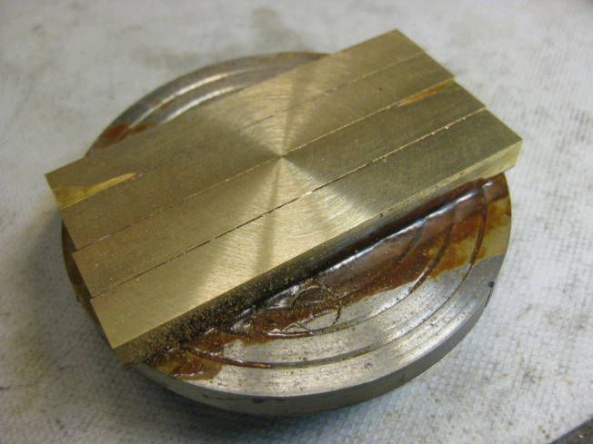
Machining 7mm square stock on a shellac chuck.


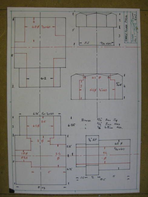
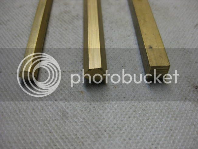
The one to be described uses a slightly larger 8mm (5/16”) square stock, which is a standard size rod. The extra thickness will allow easier fitting of blow down valves either directly to the fitting or by pipe to a valve, also the overall dimension of the top and bottom fitting will be the same rather than different. Two prototypes will be built from square stock and another two using 8mm (5/16”) hexagonal stock to see how they compare.

Drawing of the proposed water gauge which will probably be modified as the parts are made.


Materials to be used brass stock; 8mm (5/16”) square for the gauge’s main body, 8mm (5/16”) hexagonal for nuts and prototype main body. 6.35mm (1/4”) hexagonal for attaching the gauge to the boiler,


In the next couple of days I will post some photographs taken while machining the parts of the gauges.


Regards Tony.
 
Hi,

Today I made a start on four prototype water gauges.

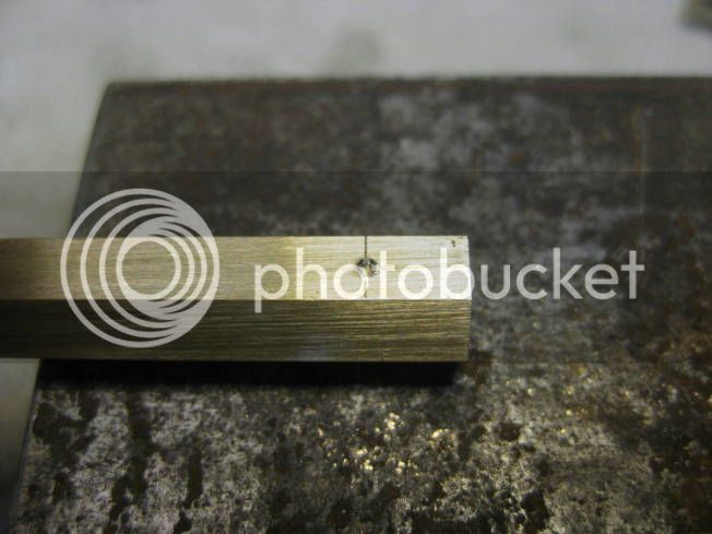
First both ends of the 8mm square and hexagonal rods were marked out on both sides for drilling the transverse holes.


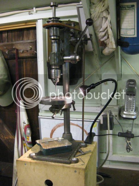
The small drilling machine used.


Setting the drill for the depth of the 3.6mm hole.


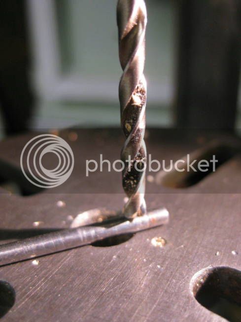
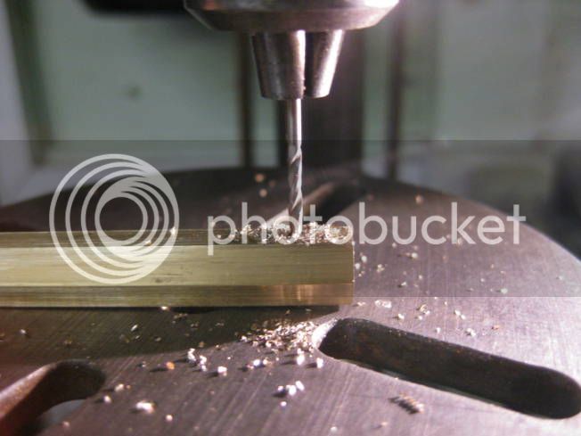
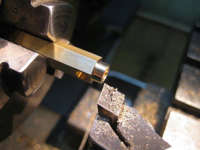
Drilling the 3.6mm hole part the way through.


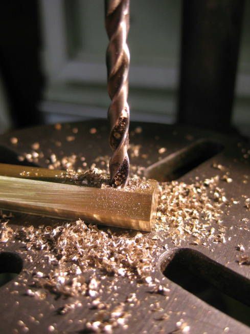
Drilling through from opposite side for the 1.8mm hole.


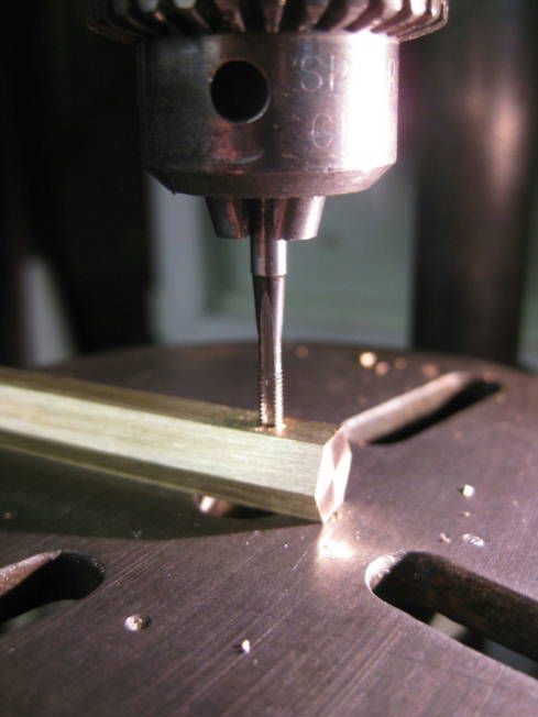
Tapping the 1.8mm hole 8BA.


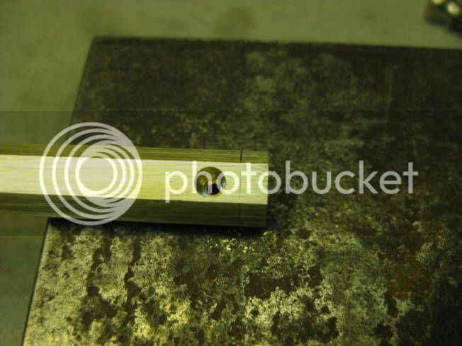
Drilled holes.


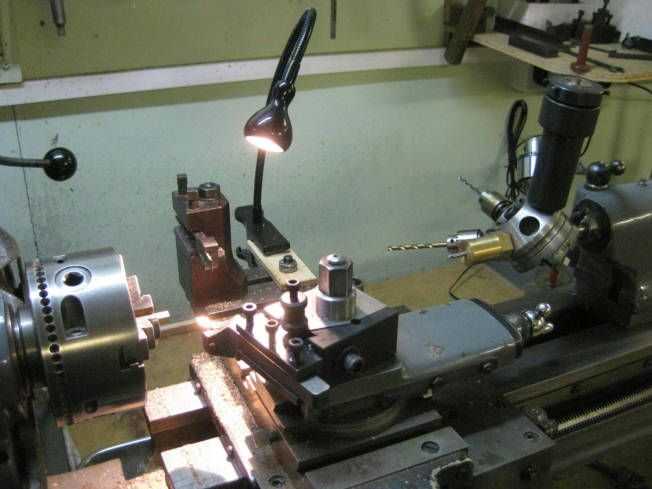
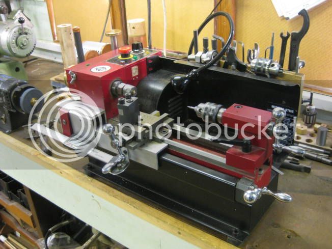
Lathe set up for machining the Water Gauge bodies.


Centre drilling end.


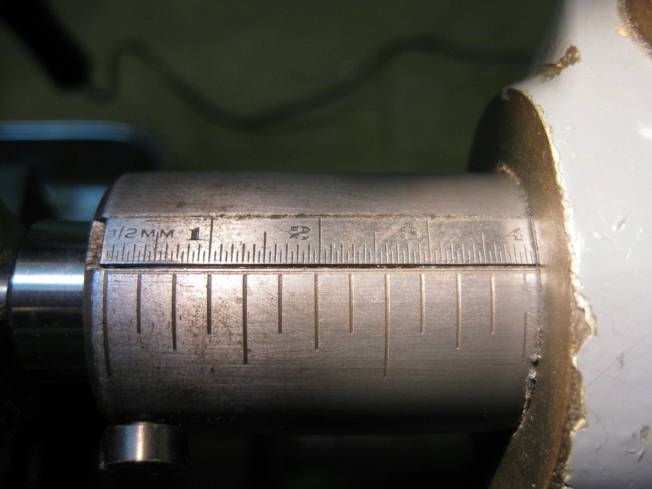
Calibrated tail stock mandrel. A short length of metric ruler has been let into the mandrel.


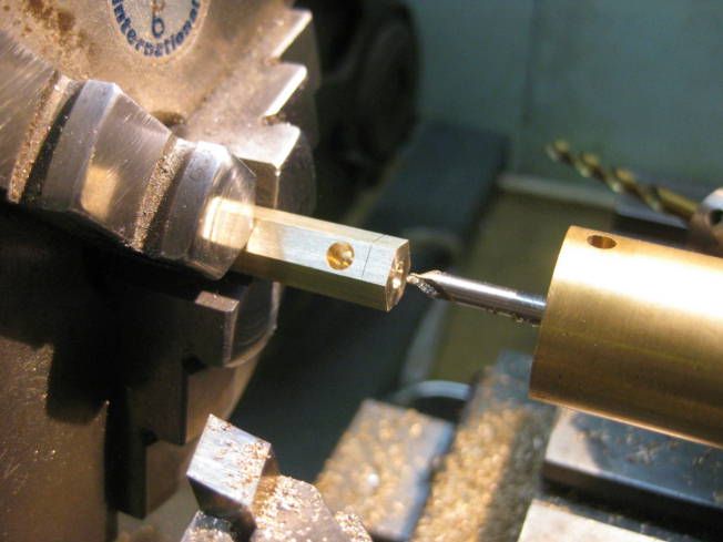
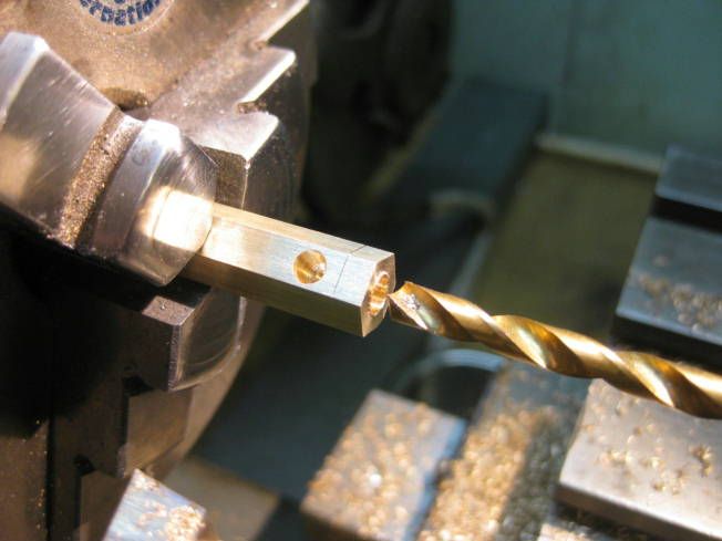
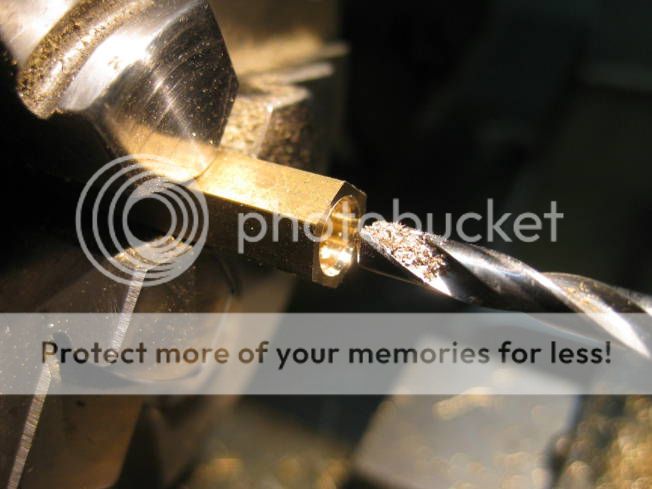
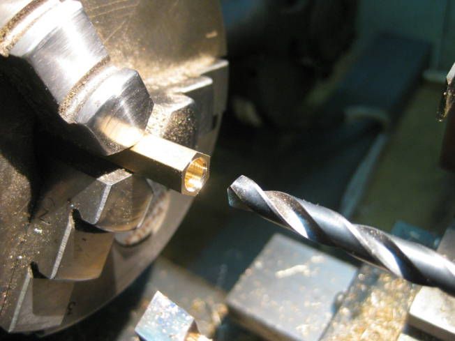
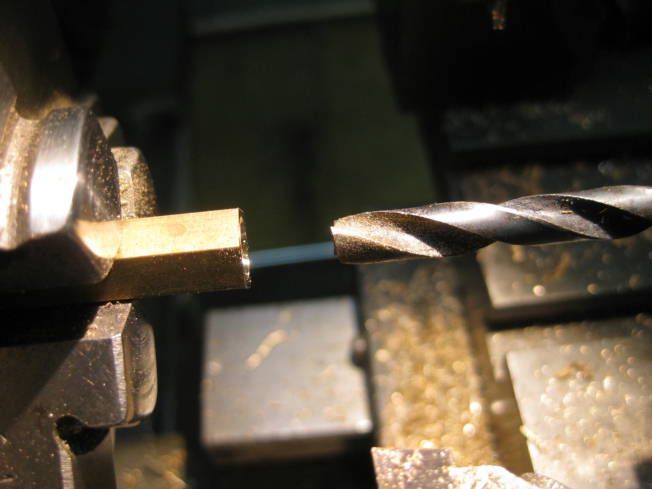
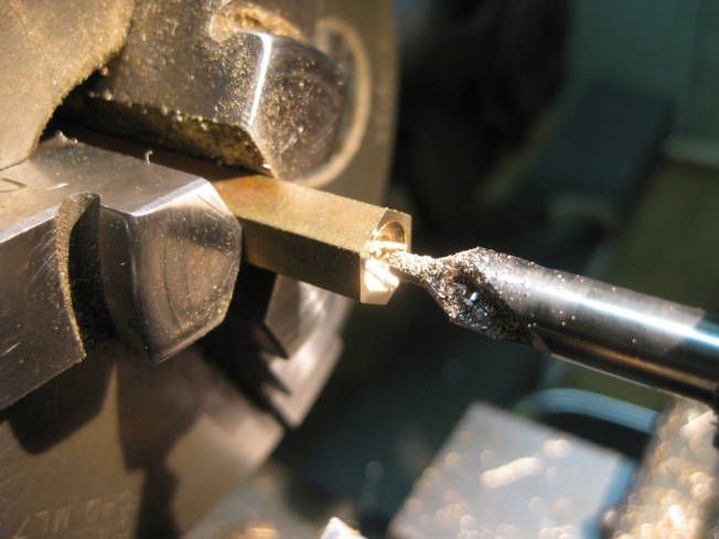
Drilling a 4.2mm hole 4mm deep. Shows scribed mark for shoulder.


No photograph of drilling the 3mm hole which breaks into the transverse hole.


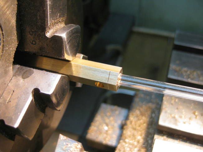
Checking the glass tube fits and will rest on the internal shoulder.


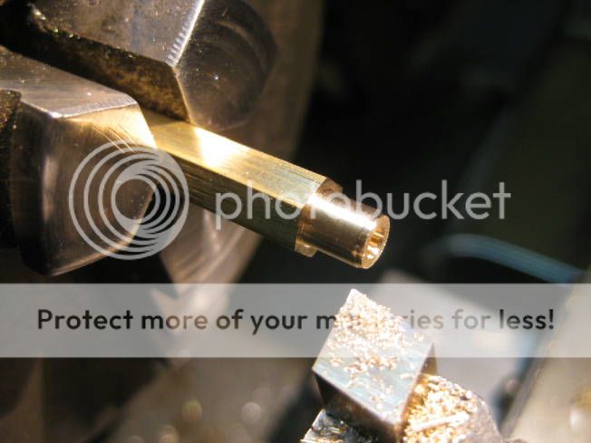
Turning a 4.8mm shoulder 3mm deep.


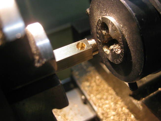
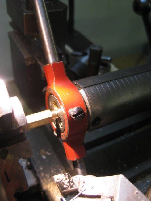
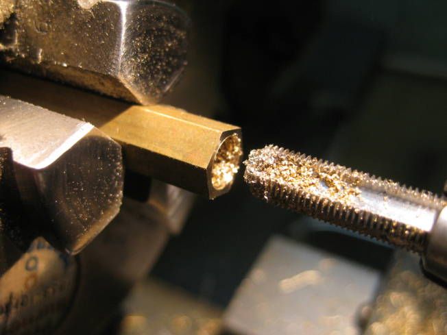
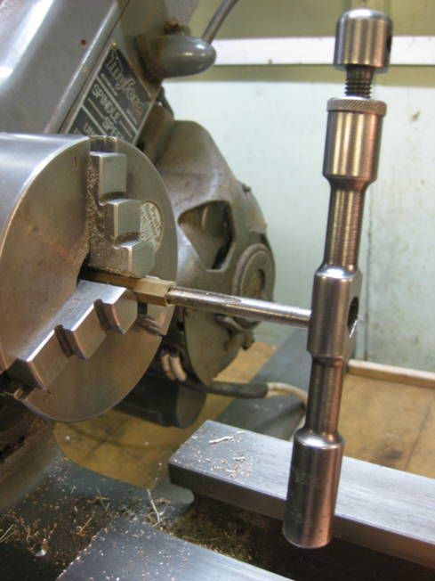
Tapping ¼”x 40 ME thread.


Reversed die to finish the thread.


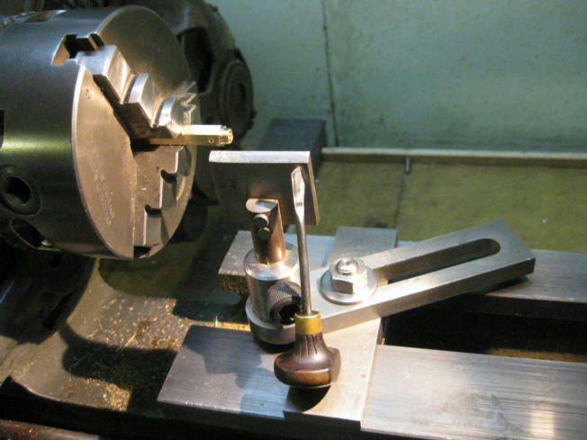
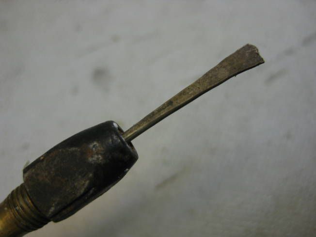
Parting graver and homemade‘T’ rest.


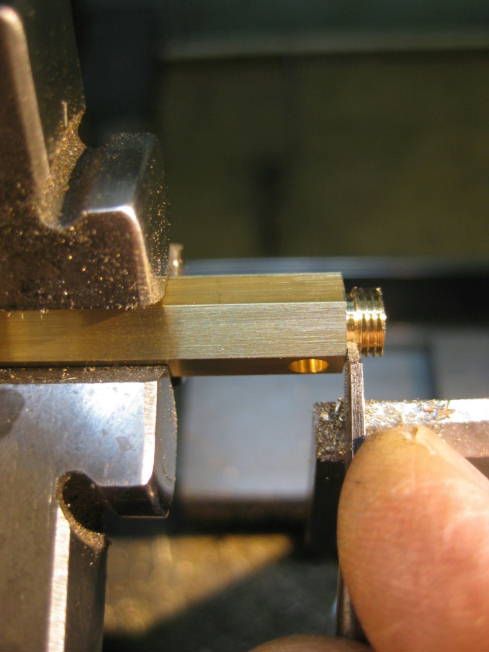
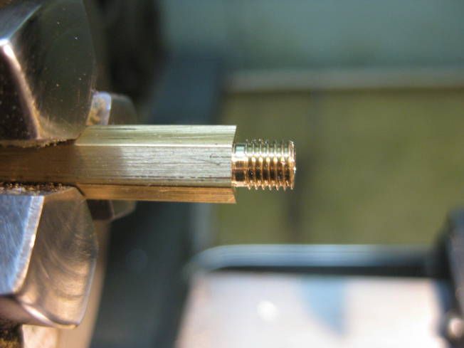
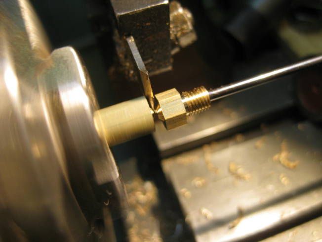
Hand turning thread relief.


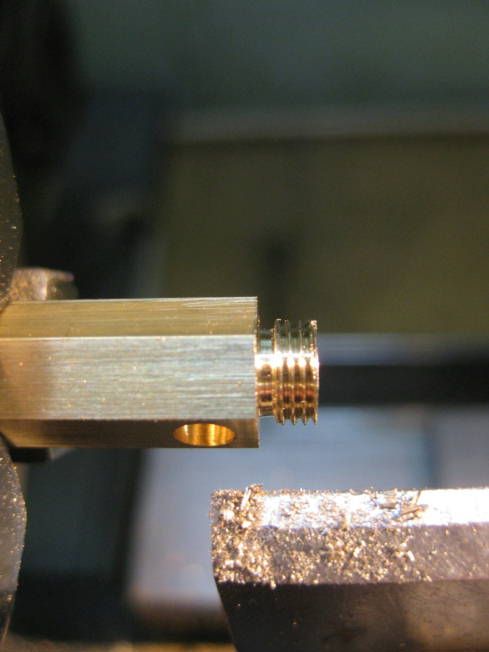
Top of thread relieved.


Clearing thread with nut.


Setting parting tool.


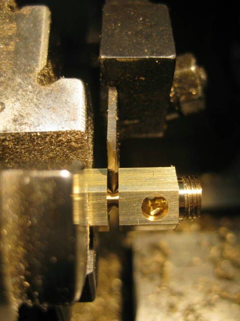
Parting off.


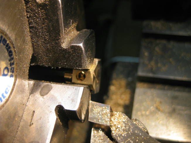
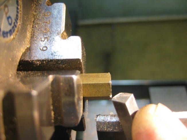
Facing end.


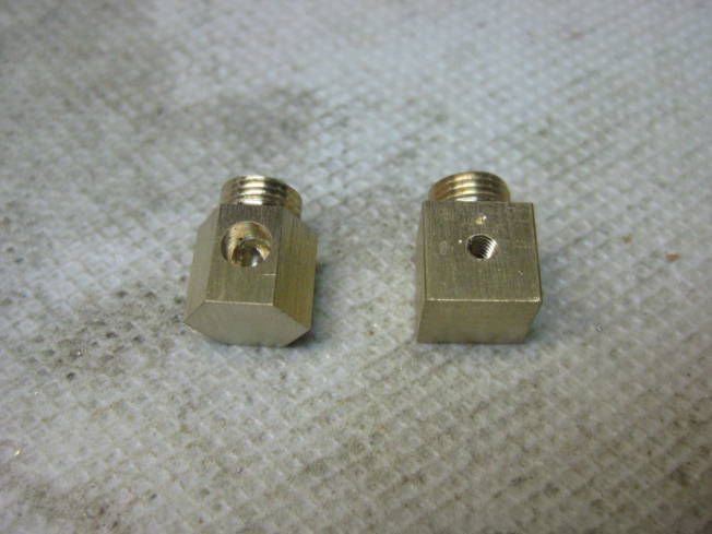
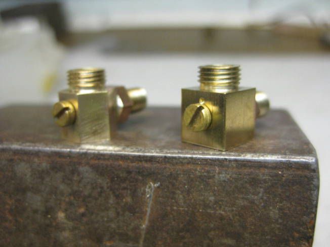
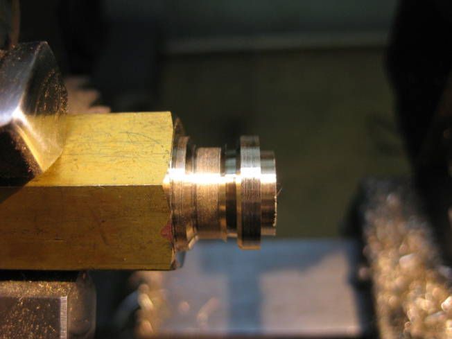
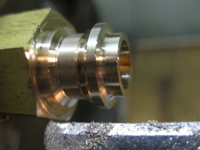
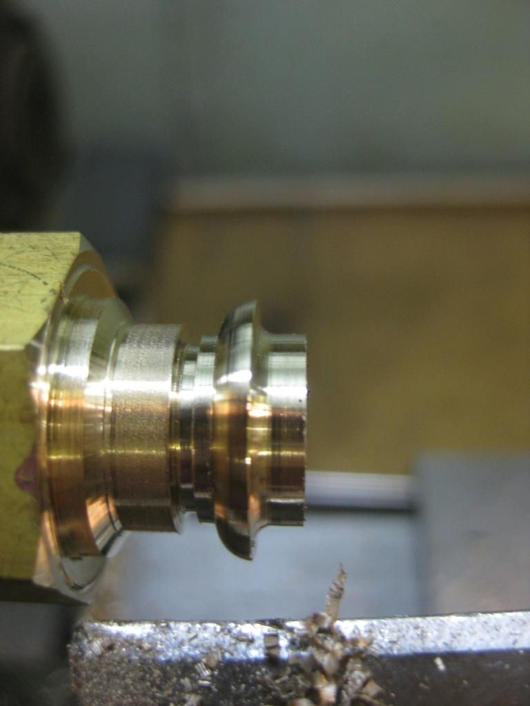
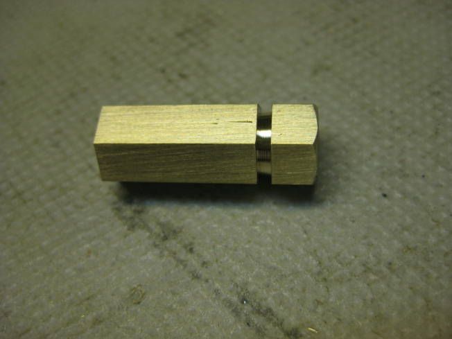
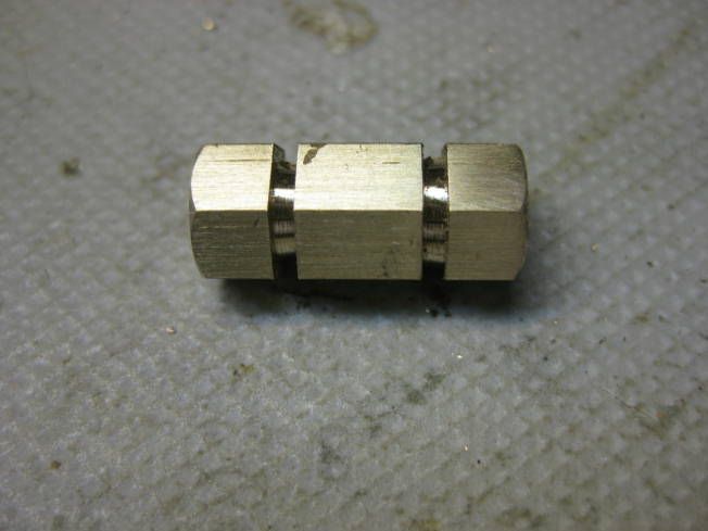
One of each hex and square bottom water gauge bodies.


I will probably get a bit more done in the next few days

Regards Tony.
 
Tony,

Lovely work and good explanation - as usual.

I'll be watching with interest.

Regards Tom
 
Very nice.

Please get good photos of how you get the thread deep enough for the nut, like the glass tube
 
Very nice, Tony. Thanks for sharing your techniques with us in a such a finely detailed way. :)

Todd
 
The water sight glasses look great sort of a side note a lot of the shows require that the bottom of the glass ( just disappearing into the lower nut) be above the crown sheet or above the level where damage occurs to the boiler. this gets pretty tough as the model gets smaller
 
Hi,

I made a start on the supports for the bodies of the water gauge today.

As with the body of the water gauge the 1/4" hexagonal rod that the bodies supports were to be made from was centre drilled before drilling a 2.6mm hole 10mm deep, then a 3mm long 3.8mm diameter should was turned.


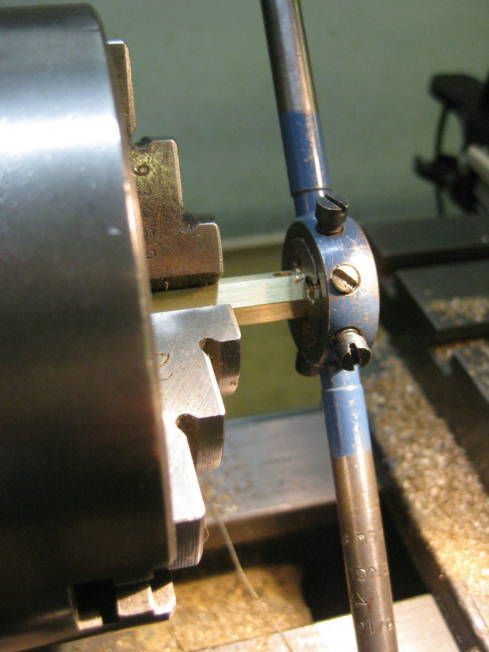
Because I didn't want to take the tools out of the tailstock turret a plain die holder was used to tap the thread.


As before the top of the thread was relieved by hand turning.


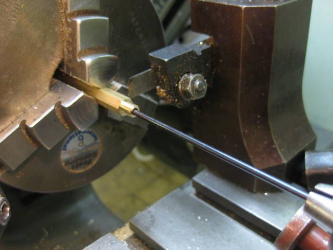
To reduce the chances of loosing the work piece when parting off a rod held in by the tailstock was placed in the work piece.


Parted and captured!


Lathe used to shoulder end of body support piece.


Turning Shoulder


Dry assembled.


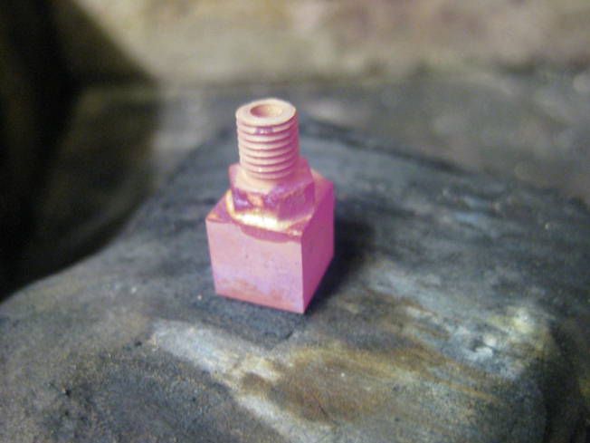
Solder. When soldering small fittings I like to hammer flat the solder so it can be presented to the joint.


Soldering.


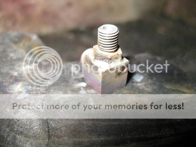
Cleaned up.


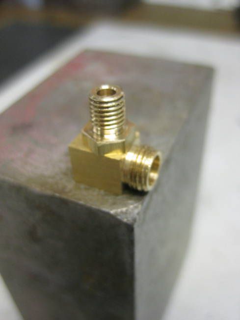
For most boiler fittings it isn't very important that they are exactly at right angles to the boiler. However it is important that the bushes fitted for water gauges are, this is how I check and correct them.


A little pull.


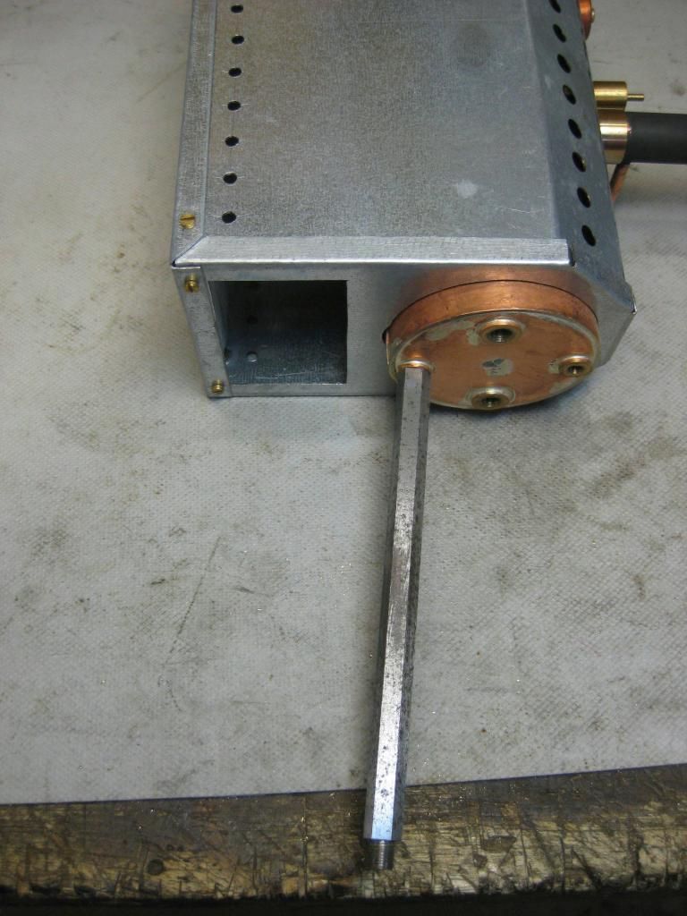
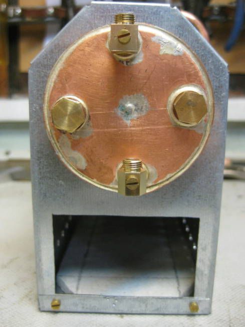
Back head of boiler with the two types of bottom water gauge bodies fitted.


Now to make another 6 of the body supports. Then if the '0' rings ordered arrive tomorrow the nuts will be made, if not the top fittings will be started on.

Regards Tony.
 
Hi,

The gauge glass '0' rings that have been ordered have yet to arrive but made a start on the nuts anyway.

Material 8mm (5/16") hexagonal brass rod drilled deep with a 1/4" centre drill.


Drilled 5.5mm, 5mm deep.


Drilled another 3mm with a 4.2mm drill.


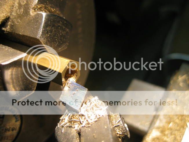
End of 5.5mm hole squared with a 5.5mm flat end drill.


Tapped 1/4"x 40TPI.


Thread finished with a flat end tap.


The flat end drill and tap are standard with their ends ground flat.


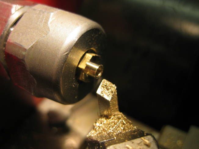
Shortening internal length of nut to 3mm.


Bevelling edge of nut by hand.


Parting off.


Squaring nut in chuck using tailstock chuck.


Facing to 4mm.


Bevelling by hand, lathe run backwards far side of nut being turned.


Clearing hole with a broach.


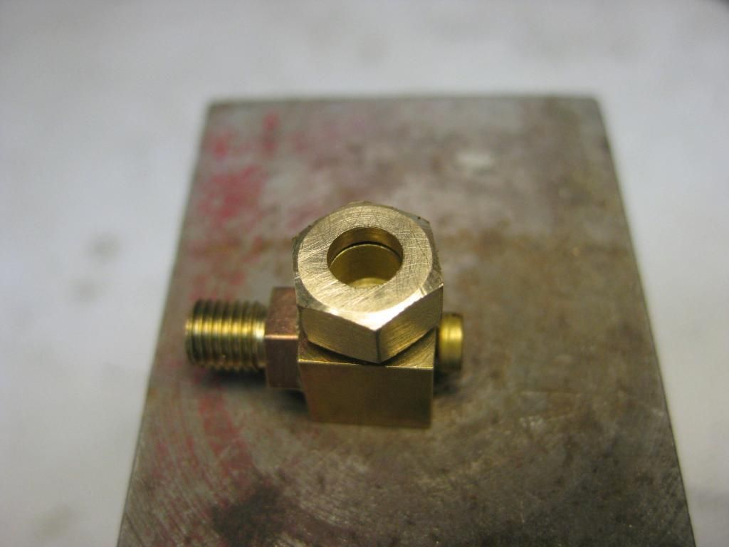
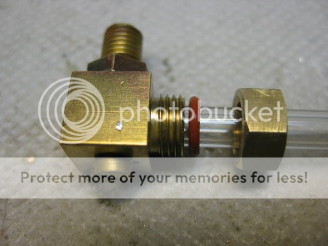
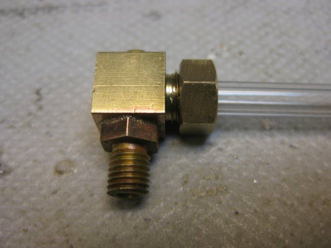
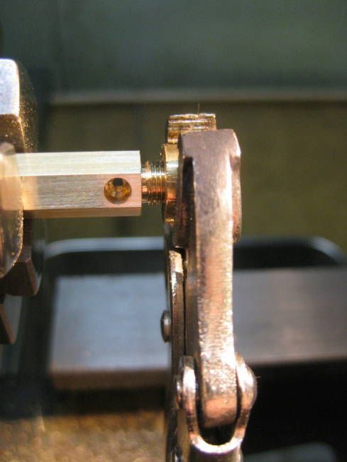
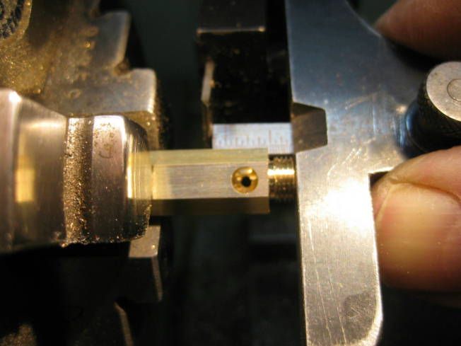
Finished fitted on body.


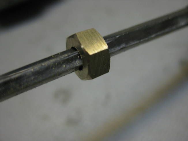
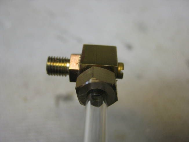
With glass tube fitted.


Sorry about the poor quality of some of the photographs. Is this what you were referring to Ron?

Regards Tony.
 
Yes, thanks. The square end drill and tap are clearly the important part. Is that a regular bottom tap, or have you ground some to make it a full thread right to the bottom?
 
Hi Ron,

The square end drill and tap are clearly the important part. Is that a regular bottom tap, or have you ground some to make it a full thread right to the bottom?

Yes, both are standard products which I ground flat though I believe it is possible to buy both.

Regards Tony.
 
Tony,

Great job. Do yoou know you should be using Bronze for boiler fittings? Brass suffers from de zincafication, and goes all powdery and can fail with disastrous results. Please keep in mind,

Regards

Colin
 
Hi Colin,

Yes I know that bronze would be better to use for boiler fittings than brass. All the boilers I make use bronze bushes and I always blow down the boilers after use, which must reduce the effects of de zincification. Is it now mandatory in the UK to use bronze for boiler fittings? Are all the commercially available boiler fittings made from bronze? It would be good to know.

Regards Tony.
 
Tony,
Thanks for taking the time to do this excellent thread. The pictures and information are invaluable to a novice like me. Seeing actual working setups is just great!
Ken
 
Tony,
Thanks for taking the time to do this excellent thread. The pictures and information are invaluable to a novice like me. Seeing actual working setups is just great!
Ken

+1 on that. This has been very helpful for me, Tony. Thanks for sharing your work. :)

Todd
 
Yes, they are, and most clubs and society's are quite strict when noticing anything that looks too yellow. I have never heard of a fitting let go when ISPs steam, but have heard of them breaking easily when being removed.

Nice thread,

Kind regards

Colin


UOTE=Tony Bird;235515]Hi Colin,

Yes I know that bronze would be better to use for boiler fittings than brass. All the boilers I make use bronze bushes and I always blow down the boilers after use, which must reduce the effects of de zincification. Is it now mandatory in the UK to use bronze for boiler fittings? Are all the commercially available boiler fittings made from bronze? It would be good to know.

Regards Tony.[/QUOTE]
 
Tony,

Although the conventional wisdom seems to be that boiler bushes MUST be bronze (and that was the case going back many years), I have, so far, failed to find any indication that it is compulsory to make all external fittings from bronze. I suspect this is the next big lie we are to be sold (like all boilers must have a boiler certificate). There is no logical reason for fittings to need to be bronze, as they usually can be replaced - whereas boiler bushes generally can't easily.

Obviously, size of loco and operating pressure may dictate different practice to 16mm/ft, but LBSC used to recommend bronze bushes, yet make all his fittings from brass.

Please continue with your informative thread.

Regards Tom
 
Hi,

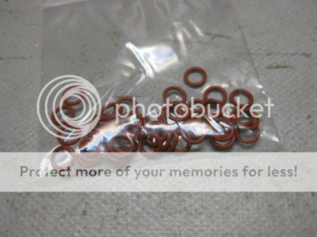
The '0' rings arrived yesterday and thankfully fitted!


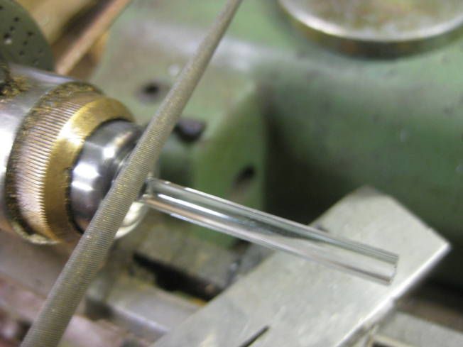
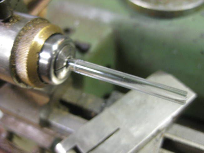
Other that cutting some gauge glasses no further work has been done on the water gauges. but now I know the '0' rings fit another seven nuts will be made.


What else I did yesterday might be found interesting and not really worth a separate posting was making a cap for a locomotive chimney. Over the winter I service the GR locomotives and stock of my model club. One of the locomotives had lost the cap off its chimney, following are a couple of photographs of making a replacement.

First some brass was drilled and roughed out using the fixed tools of the lathe then finished using hand tools.


And fitted to the locomotive.


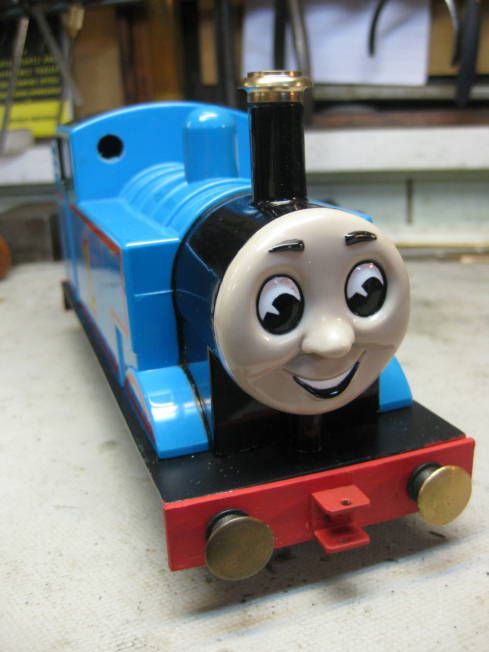
A bit OTT but Thomas does pull Santa on the GR when we have the model clubs Santa Special open day in a few weeks time.

Back to making nuts.

Regards Tony.
 
Great thread Tony, everything seems so easy while reading it. thanks to share.

By the way, amongst many, a company such as Regner uses brass for steam fittings, for bushes and even for boilers !
I would be very surprised if a club or a society refuses such high quality products during a show...
 
Hi,

All the nuts and body supports for the four prototype water gauges being made are finished.


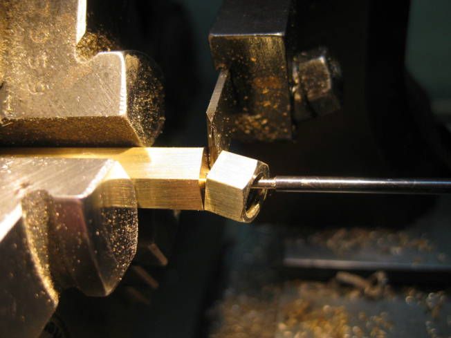
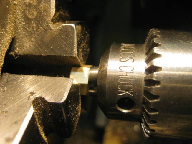
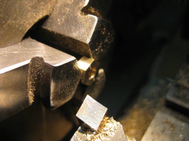
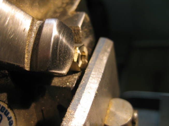
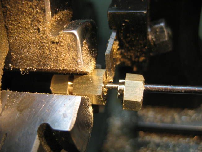
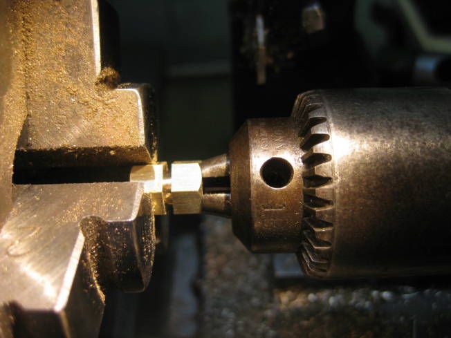
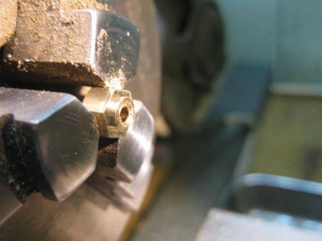
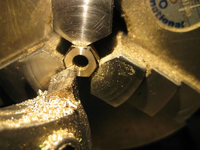
As the nuts were being made I came to the end of the hexagonal brass rod that was being used to make them. It gets to the point when you can end up with a small length of rod that cannot be held to machine. The following photographs I hope can explain how it can be done. This wasn't really necessary as I have plenty of 5/16" hexagonal brass but I don't like ending up with small pieces of virtually unusable metal anyway sometimes you don't have plenty of metal.

Nut drilled and tapped but not completely parted off.


Other end in similar state.


One of the ends parted off.


After turning nut the work piece is moved further out of the chuck for cutting off the Jacob chuck being used to true it.


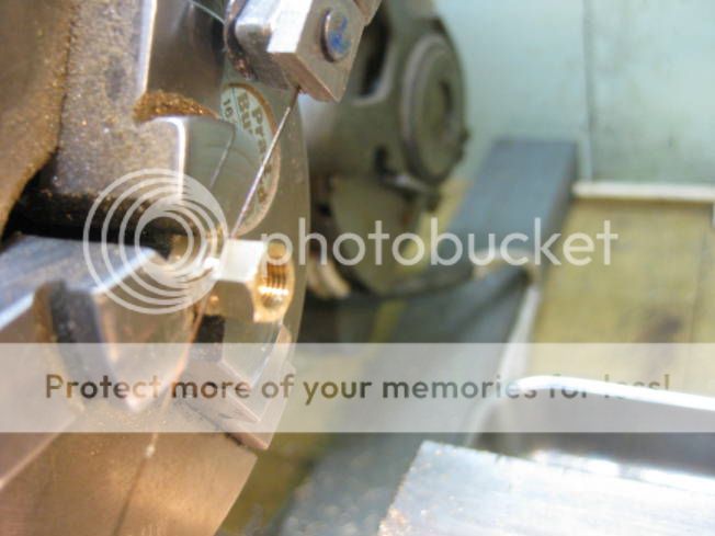
The other nut after being turned is sawn off while hand rotating the chuck.


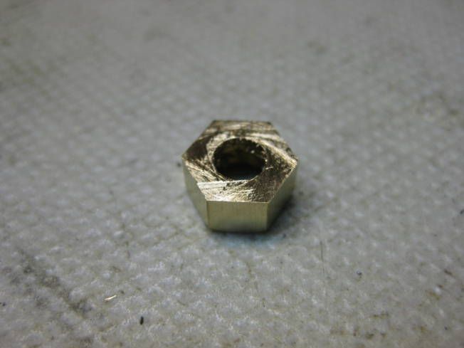
Sawn off nut.


Nut left in chuck ready for facing.


Other end of nut finished.


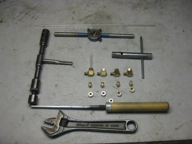
With all the nuts completely machined they were finished using the tools shown. Top to bottom; gauge glass to check hole size. Die to clean thread for nut on water gauge body. Tap to clear thread in nut. Box spanner to hold nut while tapping and broaching. Brooch to make gauge glass hole in nut round and to size. Adjustable spanner the hold water gauge body while tapping.


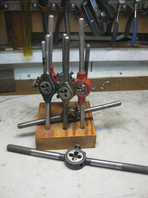
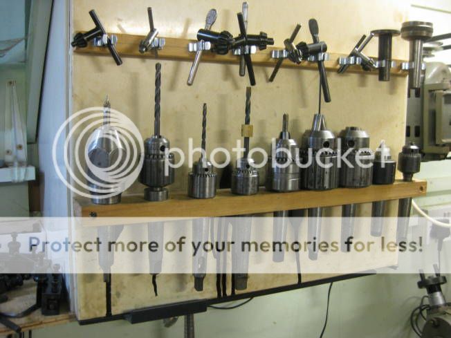
Might be of interest I have found it very useful to have a large number of Die Stocks which the popular size dies I use are left in. It saves a lot of the not having to adjust them. I have other empty Die Stocks which are used for the less popular sizes of die.


Similarly the same with Jacob chucks I have two with different size of centre drills and others used repetitive jobs such has just been done. The use of both saves a lot of time.


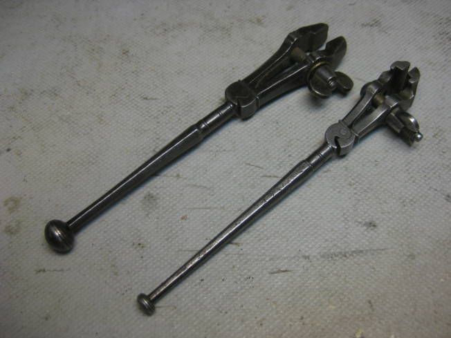
Both the die stocks and Jacob chucks for the most part were bought second hand from tool stores or alas more commonly at deceased members of my model club auctions. I have often thought how many hands some tools have go through in their life. When I was an apprentice we were expected to buy our own tools over the period of the apprenticeship (5 years) which in my case would cost nearly £300, not a lot? Well at the grand age of 21 I could expect to earn £12 to £15 a week. The reason for this rambling is that during my apprenticeship I was given the pair of hand vices below, they are Victorian or older and I have used and still use them for more than 45 years. I wonder how much longer they will be used?


Later this week the water gauge top fittings and nuts will be made.

Regards Tony.
 
Tony Bird,

Brilliant design, pictures and posts! Thanks for taking the time to post all the pictures and descriptions! I operated a small boiler in the navy that had gauge glasses like these but they were sealed with graphitic packing instead of o-rings. You learn real quick to start the boiler with the packing nuts only finger tight or else they crack right off the bat. Then you just bought yourself a 25+ valve tagout to re-replace them. As it was the things only seemed to last about a month or two.
I was wondering about one thing I saw in your post. It looks like you were able to hold hex bar in a collet for one of your operations? I didn't know you could do that? What type of collet is that and how many slits on it?

I also like your tangential tool holder. That's on my projects list.

Thanks again for all the clear, concise pictures of your incredible work!

-J.Andrew
 

Latest posts

Back
Top