Tiny Inline 4 Cylinder IC

Home Model Engine Machinist Forum

Help Support Home Model Engine Machinist Forum:

This site may earn a commission from merchant affiliate links, including eBay, Amazon, and others.
I guess I should refine my methods a little bit.

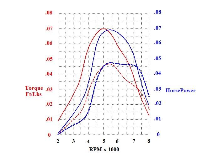
?So when I chart the torque an HP they should intersect at 5252 no matter what?

and If they don't?

Its only numbers, how hard can this be ;D

What can I do to the prony brake to make it better?

The valve seats are actually brass, but the problem is with the valves.
When I made the valves they got very thin on the seat end, and after repeated use the valves themselves have been hammered into a smaller diameter. I just have not replaced them since they are still sealing good. But it is far from ideal to say the least.

Kel
 
Ahhhh, I think I figured it out. :D

My chart is in in/lbs. I did some conversions and found that the ft/lbs are indeed equal to the horsepower at 5252.

I will have to re-conjigger the graph into ft/lbs.


Kel
 
Here is the new revised graph.

This looks much more like the real deal.

DynoComparisonChart-1.jpg


Kel
 
Looks much more normal, or at least what I am accustomed too. :bow:
 
Thanks Jeff,

What type of Dyno are you planning on using this weekend?

Kel
 
Well it wont be anything if I cant find a place to buy E85.
When you have a propeller mounted to your engine, the diameter, pitch, and rpm all corelate to a horsepower. Simpler, not as detailed, you have to have an assortment of different props to obtain a wide range of readings, but its functional enough until I get around to building a water brake. :)


Lakc said:
Well it wont be anything if I cant find a place to buy E85.
When you have a propeller mounted to your engine, the diameter, pitch, and rpm all corelate to a horsepower. Simpler, not as detailed, you have to have an assortment of different props to obtain a wide range of readings, but its functional enough until I get around to building a water brake. :)

Cool, a water brake dyno. How are you going to meter the water inflow and outflow?


Well, I did it Now, I killed the little guy, but I am totally stoked at the same time.

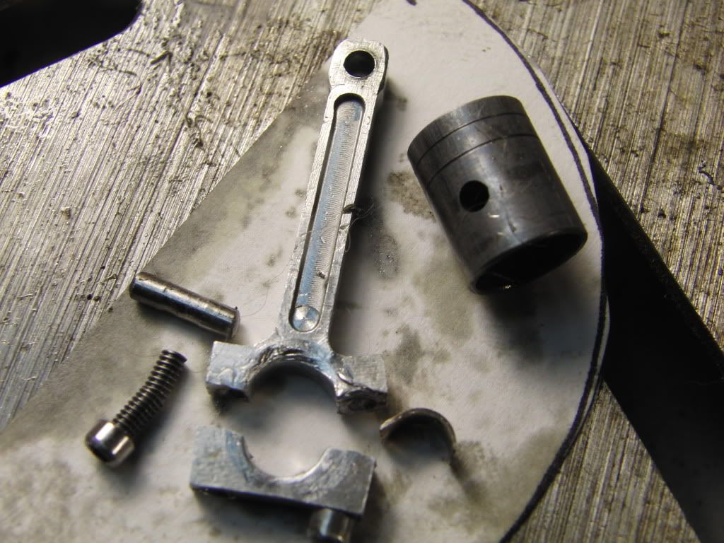
During yet another high load run on the dyno, the engine started to knock louder than usual, I knew it had to be that sloppy connecting rod.

So I locked the throttle wide open, put on a face sheild and stood back. I had it pulling a load of .8 in/lbs, when BAM the engine stopped dead. I could no longer turn the engine over, something had broken.

I took the engine apart and found this.
CIMG2475.jpg

Does it get any better than this ;D

You can see that one of the bolts bent, and the other one snapped of flush with the cap bending it and the rod in the process. The side of the rod is worn down considerably, and half the bronze bearing was no where to be found.

I inspected the rest of the connecting rod bushings and they are all pretty much gone, but no major failure. The crankshaft will need to be replaced, as the journals are shot, along with a new set of connecting rods.

Too much Fun ;D

Kel

 
Cool ;D :eek: ;D

"Gentlemen, we can rebuild him. We have the technology. Better than he was before. Better, stronger, faster."
 
Hi Kel,
I know you're having fun but while you're doing the rebuild I would consider adding an oil pump. It could be and external dry sump type which could be driven off the front of the crank. The reason I'm saying this is because loading and engine as hard as you have been doing with a splash oil system is asking for trouble. You could put a manifold along the outside of the block at the main bearing level and feed into the sides. From there you could drill the crank and feed oil to the rods.
My little 4 cylinder engine is a screamer like yours and even without loading it the rods just take a beating. About every 4 hours of running I have to check and adjust the caps to eliminate the clearance. The mains on the other hand have held up quite well but then again they don't get the beating that the rods do.
Have fun,
George
 
Thanks for the tip George!

I do plan on doing more hard testing with it to see how much power I can get from it, and an oil pump would defiantly help a lot, especially if I increase the bore from .391- .5 ;D

Kel

 
Oooh, detrius. 8)


kcmillin said:
Cool, a water brake dyno. How are you going to meter the water inflow and outflow?

SIC had plans for one, its what actually sold me on this hobby. When I get around to building, it will probably be updated with solenoids and all microprocessor controlled.
 
KustomKB said:
"Gentlemen, we can rebuild him. We have the technology. Better than he was before. Better, stronger, faster."

That was the Idea ;D

I already started designing the "High Performance Upgrades" for it, I have a lot of room in the $6 million budget ;) jc vvv

I am now seriously thinking into the oil issue. With an oil pump, how do I meter the oil to be certain that oil is reaching all the connecting rods? My initial sketches have the passages connecting two crank journals to one main journal.

Also, I am contemplating a "Dual Purpose" water pump/oil pump. Same design as now, just doubled up with two separate chambers. One for oil, and one for water.

My thought is, with the oil pump above the level of the oil, will that cause any issues?

Any Ideas for a "Tiny" Oil Filter? The last few runs yielded some metal flake paint bad oil.

Kel

 
So I am in the beginning stages of the High Output TI4 Design.

My current firing order is 1-2-4-3, and I want to get 1-3-2-4.

My thought is that the way it is now with the intake manifold having two runners connected to two pairs of cylinders, the characteristics of the flowing gas is not the same from one cylinder to another, and could be affecting fuel mixture, or inflow into the cylinder.

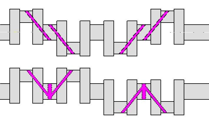
with the conventional crank design (Shown on top in picture) I cant get away from a firing order of either 1-3-4-2 or 1-2-4-3. The head design has the intake runners from 1&2 and 3&4 intersecting each other in the head, and I like the intake manifold as is.

With this design the intake gasses entering the intake manifold on one side gets sucked into one cylinder immediately followed by its married cylinder. So the gasses have more time to accelerate (in the shared runner) to the second cylinder than the first in the firing order.

So in order to get the firing order to 1-3-2-4 I need to make an unconventional crank design. With 1 & 2 on the same plane, and 3 & 4 180 degrees off from 1 & 2.

Like this.

CrankComparison.jpg


The top is the conventional design, and currently what I have.
The bottom is my proposed design.
The purple lines are oil passages.

I have not found any pictures of any crank like the one I have designed in the bottom. I think there might be a reason for this. your thoughts?
Am I nit picking here, or do I have a legitimate worry with the intake flow pattern?

I already know the engine will run great, but now I want it to RACE!!

I suppose I need to re-design the head anyway, perhaps I should make 4 separate intake runners in the head.

I have more questions for a later date.

Kel

 
Kel,
The reason that the conventional crankshaft that you have drawn is used it because there are two rocking couples that tend to cancel each other out. The first couple is between pistons 1 and 2, and the second between 3 and 4. Looking at only a 2 dimensional plane as you have drawn, say the first couple tries to rotate the crankshaft in the length wise direction clockwise at the main journal between 1 and 2 then the second couple tries to rotate the crankshaft counter-clockwise around the journal between 3 and 4.

In your proposed layout there is only a single rocking couple with pistons 1 and 2 forming one half and 3 and 4 forming the second half. This will produce a rocking motion centered on the center main journal.

Gail in NM
 
I think your absolutely correct in thinking there is a good reason they dont do that, although the reason escapes me at the moment.

And as I typed that I see Gail piped in with a very valid concern.

You want to make horsepower, and while every part of a design provides ample ways to loose horsepower, the crankshaft is pretty straightforward. Wider journals and larger diameter throws cause more friction, but those areas are traditionally saved for the last fractions of HP gain, not the first. The rocking couples might not be a game ender at our scale, but there are far easier changes to make first.

Start with the simple basic fact, air+fuel=power. More air and more fuel, in correct proportions, makes more power.

Generally, that means bigger intake valves, smoother air transition into the cylinder, good combustion chamber shape. The cylinder heads are what seperates the men from the boys in the racing world.

Intake manifolds are important too. Runner length and design all have a big effect. Look up the Mopar "long rams" for some interesting pictures. Long runners to a central mixing area just might fix your current problems.

Just some food for thought. :D
 
Thanks for the info Guys. Every bit helps.

I am now set on the original crankshaft design, stick with what has been proven is a good starting point.

The largest factor in the High Output design is the pistons. Increasing the bore from .375 to .5" will nearly double the displacement from 3.62cc to 6.42cc. As the old saying goes "There is no Replacement for Displacement"

This will allow me to increase the size of the valves from .156" to .219". My current sketchings have the intake valve .219" and the exhaust valve is .203".

So, I am pretty set on having lapped pistons, my numbers on the dyno have convinced me of their benefit.

The problem with cast Iron lapped pistons is their weight. The original aluminum pistons were 4 times lighter than their cast iron counterparts, and increasing the size of the pistons will undoubtedly add a whole lot of reciprocating weight, putting even more strain on the already troublesome con-rod journals and bushings.

So my plan is to put aluminum inserts into a cast iron sleeves. My problem with this is the thermal expansion of both metals is different, so what type of fit do I need to ensure the pistons don't come apart during high speed, high load runs?

The thought of cast iron rings is indeed in my mind, but for now I wan't to stick to my comfort zone.

Kel
 
Hi Kel.
First I have to say thanks for the great plans I received. Have been studying all weekend. And I have started going through the scrap-containers( with good luck ;D) at work for aluminum for the cyl-block and oilpan.
Have some questions.
#1: Is there any reason not to make the oilpan in one piece.
#2: Considering the cyl.-boreYou have allready answered it. I'm planning on using some nice valveguides w/innerdia 7/16"
#3: I'm planning to use brass/bronze conn.rods.

Best Regards
CS.
 
Hello CS,

Glad to hear you have already started to material selection process.

There is no reason not to make the oil pan in 2 pieces. I was limited by my material selection, but if you have a piece big enough, go for it.

Making bronze connecting rods is a good idea. That is part of my High Output design thus far.

Kel
 
kcmillin said:
So my plan is to put aluminum inserts into a cast iron sleeves. My problem with this is the thermal expansion of both metals is different, so what type of fit do I need to ensure the pistons don't come apart during high speed, high load runs?

The thought of cast iron rings is indeed in my mind, but for now I wan't to stick to my comfort zone.

Bimetallic pistons would seem to be much more of a leap then just cast iron rings. While 8k rpm is a lot on some bigger engines, your pistons might be ok at that speed. Just try and keep the weight down by thinning out where possible.
 
Hi Kel.
Thanks for replying.
I am a traveling repair/service mechanic and I'm visitting all of the shipyards around here.
And every place there are some nice guys supplying me with all kind of metall offcuts for free ;D, or a sixpack now and then :big:

Regards.
CS
 

Latest posts

Back
Top