The "Weeble", wobbles into being.

Home Model Engine Machinist Forum

Help Support Home Model Engine Machinist Forum:

This site may earn a commission from merchant affiliate links, including eBay, Amazon, and others.
Hi Y'all

This thread got a little off track but I'm going to try to bring it back to center.

I’m going to spend some time and effort fine tuning the Weeble before completing the plans for posting. This is the first build of an original design and deserves to be tested more thoroughly before presenting it to others to build. I want to be a little more confident in a few of the details. A number of ideas occurred to me as I was building it that may have improved the design that I did not go back and incorporate. Mostly these are procedural ideas and a few are refinements and simplification. This is after all a very simple design and that is how it should be kept.

Mostly , I want to fine tune the performance. I hope to be able to include some specific performance data from the tests. From input on this forum I now know how to build and use a Prony Brake to test output power and torque.

More to follow soon.

Jerry
 
Fix number 1.

Air pressure leaks at the shaft/bushing ends needs to be sealed. This seams to be common to rotary valves. By slipping an o-ring over the shaft and compressing it with the crank web at one end and the flywheel at the other end stopped the pressure loss but the increased friction stopped the shaft from turning. Easing up the pressure between the crank and the flywheel reduced the friction but increased the air loss.

Delrin washers to the rescue. The first washer has a 1/4” ID x 1/32”thick. This is followed by two washers with a 3/8”ID and a final washer with 1/4”ID. Trapped in the space between the shaft and the two center washers is an o-ring with 1/4”ID by 1/16”thick. All well oiled. Slight pressure on the flywheel before locking the grub screw compressed the o-ring enough to seal the air loss with very low friction.

This drawing is not to scale but illustrates the relative positions of the o-rings (black), the washers (blue), the shaft and bushing (gold), and the air pressure (red, exaggerated).

With shafts and bearings of larger diameter it might be possible to fit the o-ring on a groove in the shaft that would fit within the bushing. If I could find an o-ring with a thickness of about 1/64”, I would try that.


thrust bearing.jpg
 
Hi Y'all

Installing the thrust bearing / seals made a big improvement. Preventing air pressure loss puts it to work turning the engine.

Here is video of the engine running slow with no flywheel. There is almost no inertia in the rotating mass. The four cylinders provide overlapping power strokes 90 degrees apart, like you get with a two cylinder double acting engine with offset crank. Valve timing turns out to be very important. Just a few degrees earlier or later changes the performance substantially.


<embed src="http://www.youtube.com/v/BOstqRnnJa8&hl=en&fs=1></object>

It is fairly easy to change the timing on this engine but the engine must be stopped. I wonder if there is any way that this could be done on the fly? Any suggestions?

I’m going to try some different flywheels to get a better understanding of the effect of weight and diameter.

Jerry
 
Now THAT is impressive Jerry.
I can't think of any other engine that I've seen run without
a flywheel, propeller or some other type of mass for inertia.

Great project!
I'm looking forward to more on it.

Rick
 
Hey... :bow: excellent :bow: work there.

Regards

Philly
 

Today's project was to test the effect of different flywheels on the Weeble. I have been able to get the engine to run at low speed without a flywheel. All it takes is very low friction, low air pressure and careful valve timing.
I am controlling the speed with a small regulator that is about 18" from the engine through 1/8"ID plastic tubing. I believe that it is important to keep the distance between the regulator and the engine as short as possible and rigid tubing would also be better.

I have read several post elsewhere on the forum that suggest restricting the exhaust as a means of control but since this engine exhausts through the drive shaft, I can not try that.

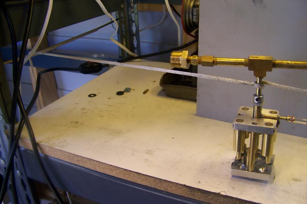
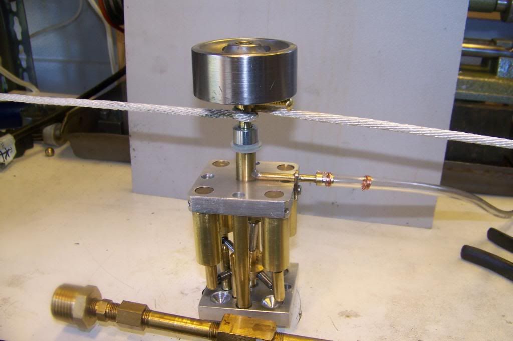
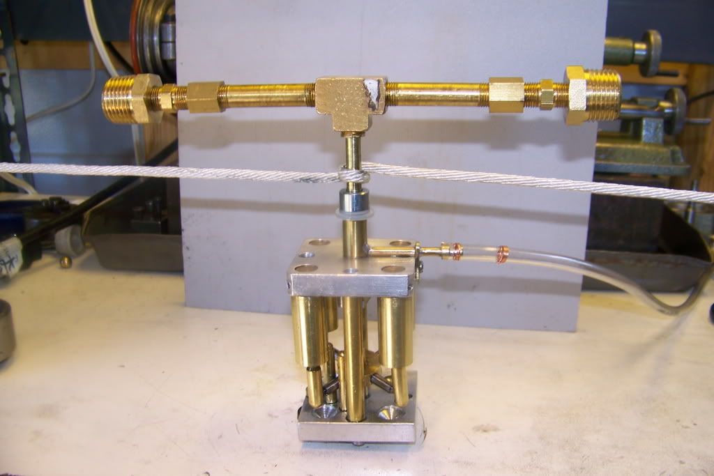
I intend to test the engine using several different flywheels and loads at different air pressure settings. Here is the setup.

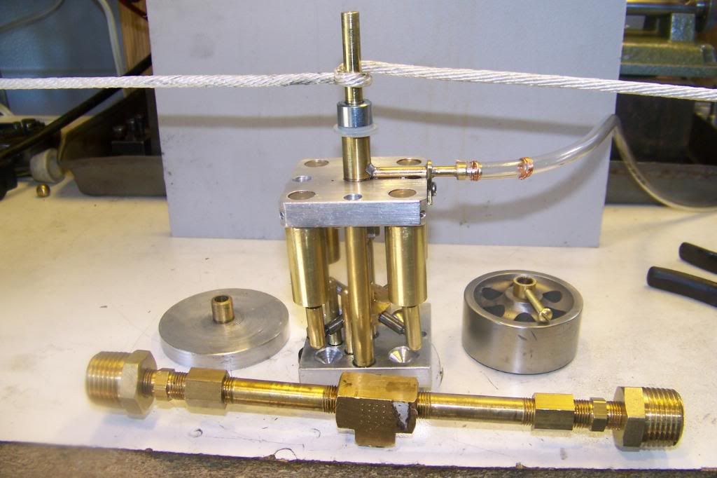
WeebleEngine007-1.jpg

WeebleEngine012.jpg

WeebleEngine013.jpg


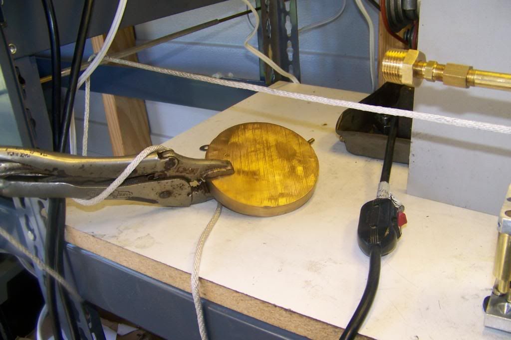
The engine is mounted with the shaft vertical. A fixed load is provided by a two pound (approx) weight. The weight is attached to the left end of the strap and hung over a pulley. The right end of the strap is fixed. This provides a constant load for all tests. If the engine will not start under load the weight is lifted to allow the engine to come up to speed. The weight is then lowered and the air pressure reduced until it stalls. To be more precise, I should have a tachometer and a digital scale but by keeping the load equal throughout all test, I can at least get comparative information.

Test #1 with no flywheel required at least 80PSI to run. A slight increase in load or reduction in pressure would result in instant stall.

WeebleEngine007-1.jpg


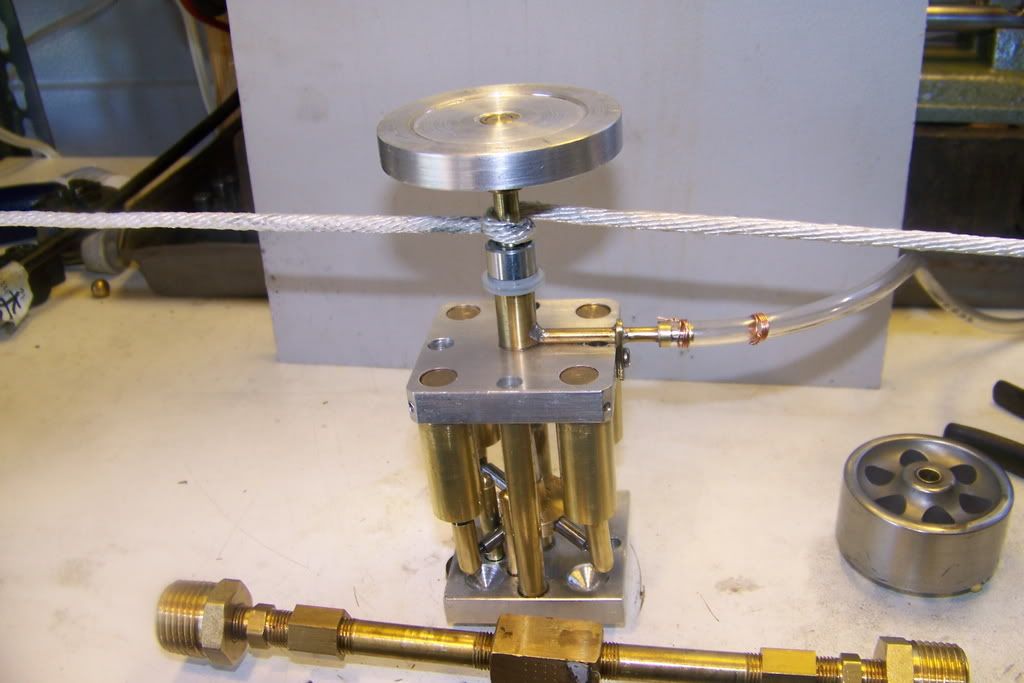
Test #2 with a lightweight aluminum flywheel would not self start but would run reliably under load from 80PSI down to about 60PSI. The lowest operating speed estimated 200-300 RPM. Difficult or impossible to anticipate stall.

WeebleEngine008-2.jpg


Test #3 with the original cast iron flywheel. Much like #2 but slightly easier to anticipate stall and recover by increasing pressure. A sensitive governor may be able to prevent stalling but would take carefull adjustment.

WeebleEngine010.jpg


Test #4 with a cobbled up flybar. This flybar is heavier and carries the weight at a greater radius from center. With this flybar, the engine could be made to start under load if carefully positioned before opening the air flow. It would start at about 30PSI and could be throttled down to about 20PSI. It was very easy to anticipate stalling and by carefull control of the regulator could be made to run at very low speed under load.


WeebleEngine011-1.jpg


It also provides a nice chuff-chuff-chuff from the exhaust when accelerating. I was able to notice a missing 4th chuff in the cycle which I think means a lazy cylinder, probably poor fit of the piston. Here is the video:


From these test I conclude:

1. Matching flywheel to LOAD is important. Flywheel did not seem all that important until I applied a reasonable load.

2. Heavier is better, and weight distribution is important. I'm going to search the forum for all the posts on flywheel design.

3. Fiddling around is as much fun as making chips.

Best to all.
Jerry
 
Nice going Jerry! great engine, for a minute there ,I thought your load test was to see how far you could fling a pair of vice grips (with big chunk of brass in them!), with the generated torque!

Giles
 

Latest posts

Back
Top