T head engine by Brian

Home Model Engine Machinist Forum

Help Support Home Model Engine Machinist Forum:

This site may earn a commission from merchant affiliate links, including eBay, Amazon, and others.

Brian Rupnow

Design Engineer
Project of the Month Winner
Joined
May 23, 2008
Messages
15,259
Reaction score
8,544
Location
Barrie, Ontario, Canada
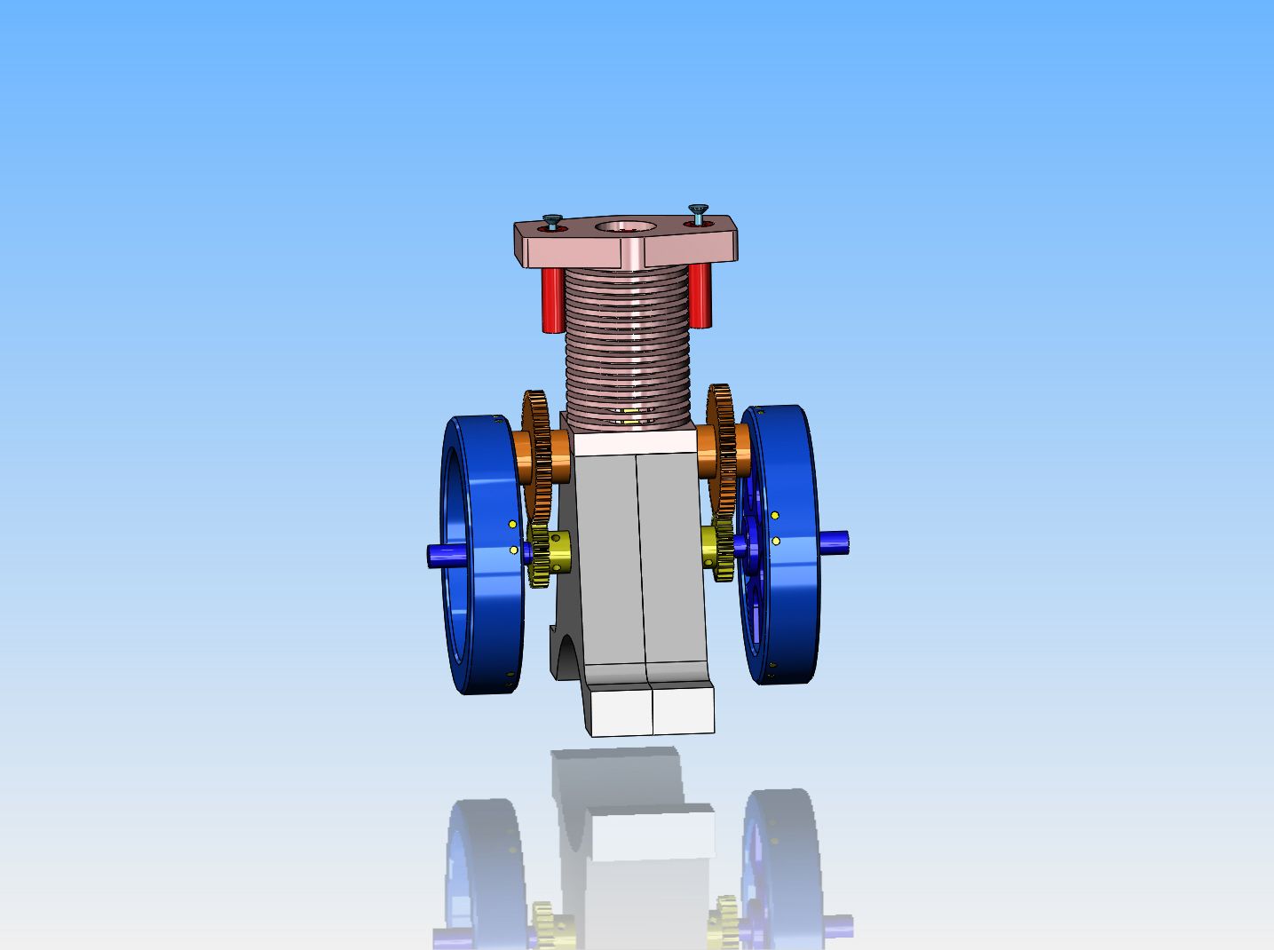
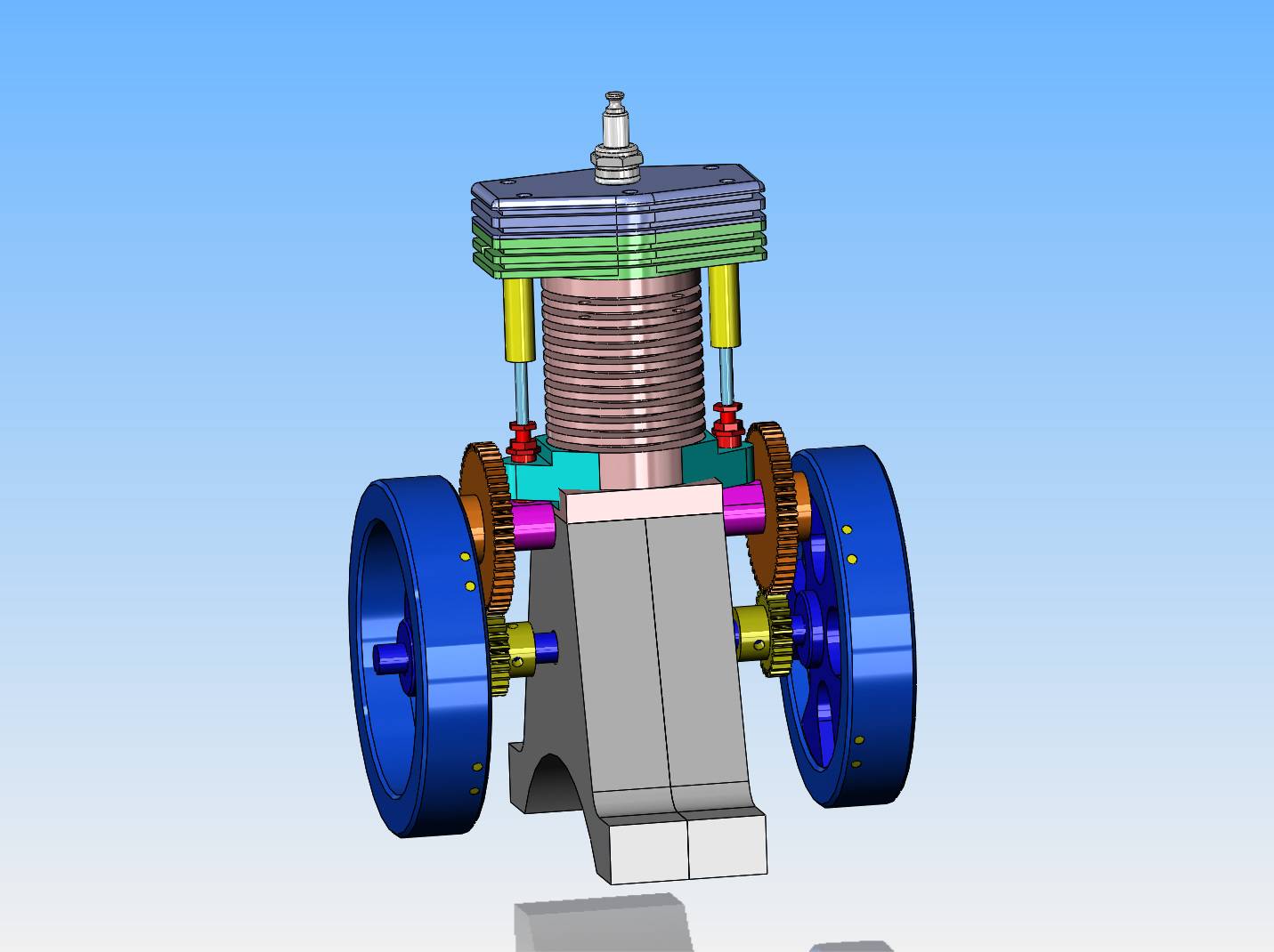
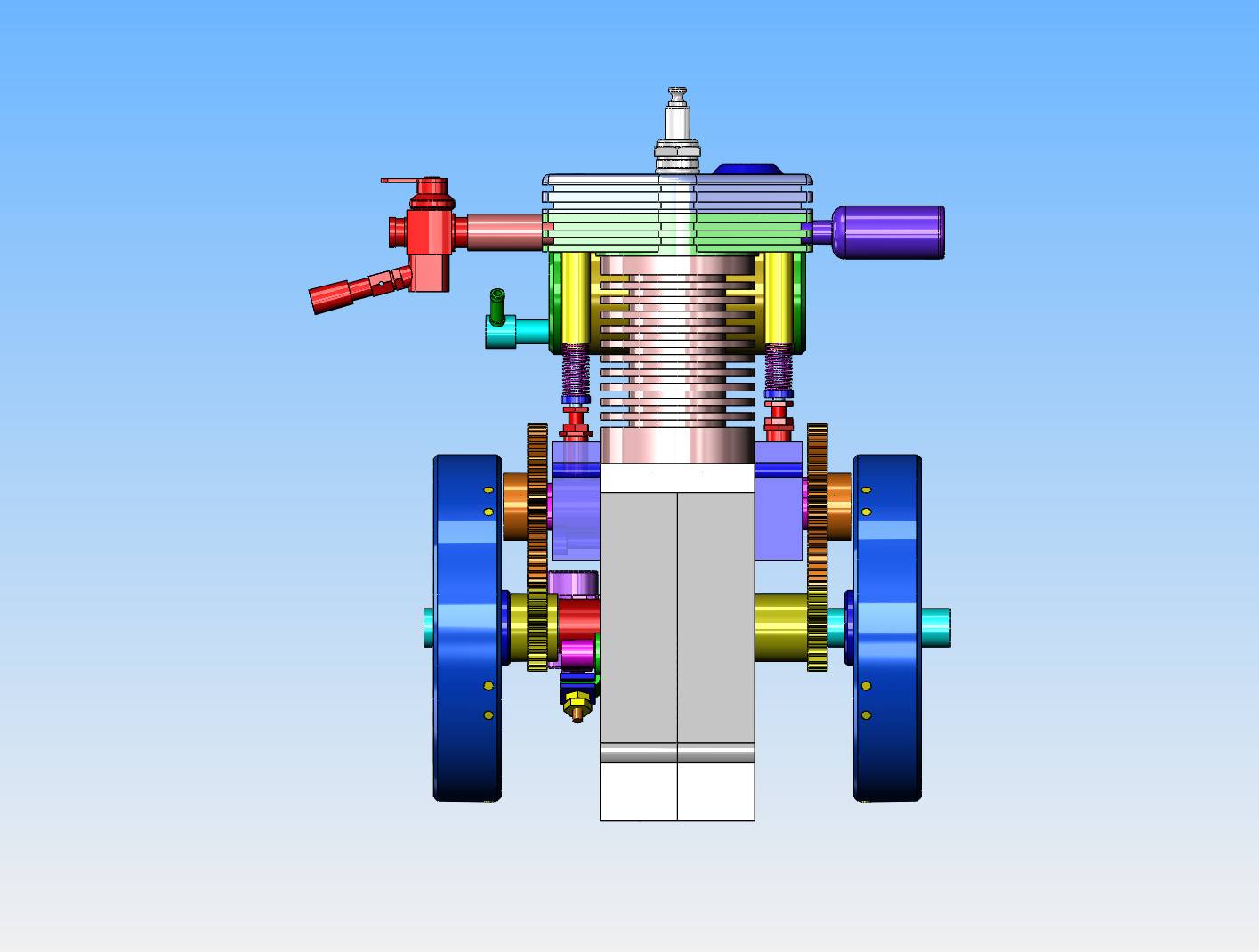
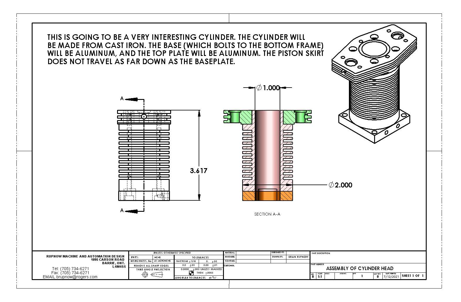
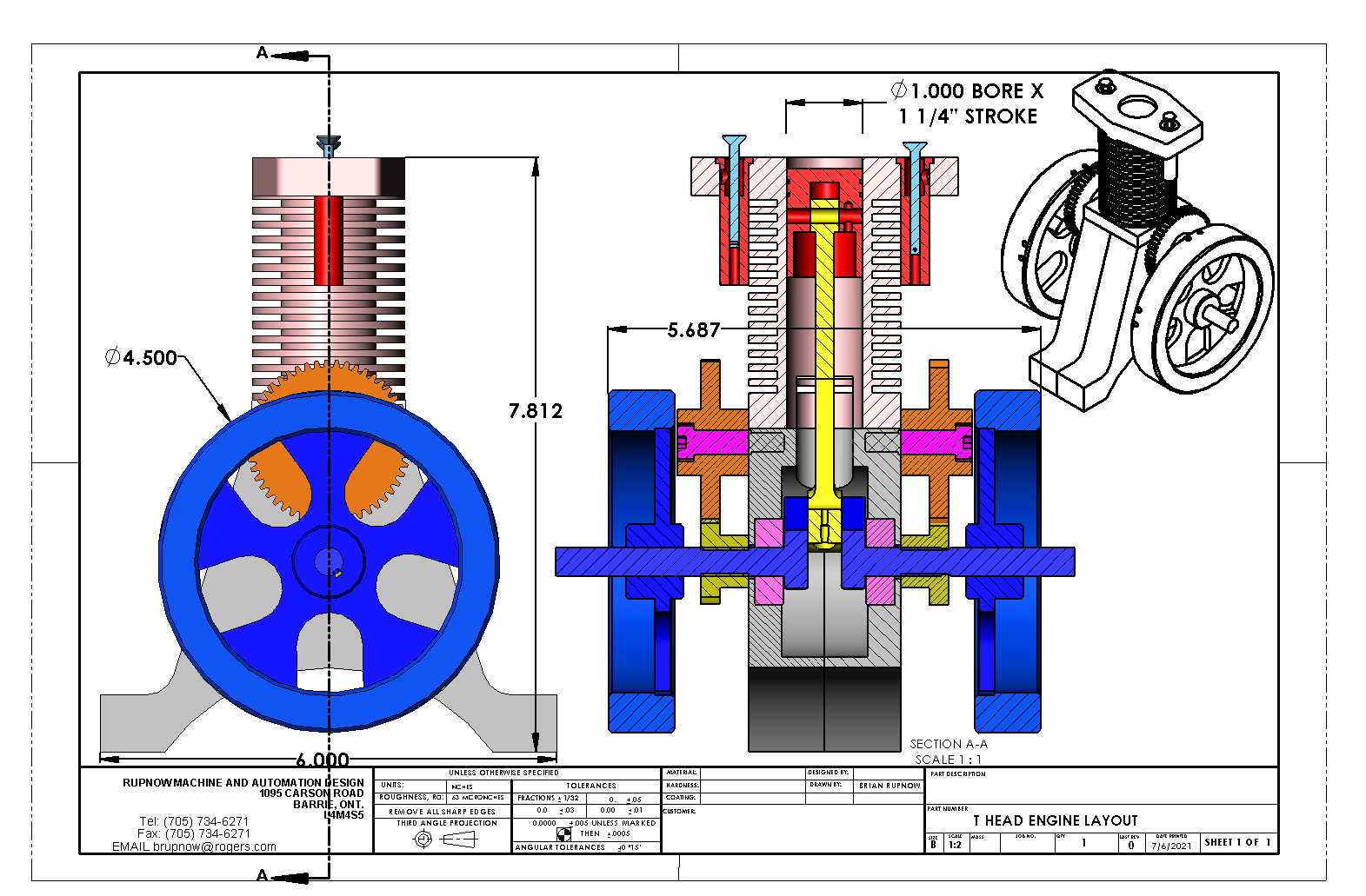
Today seen the beginning of a new engine.---The design phase, at least. After recently seeing an Upshur T head coming together on HMEM and a post by Vederstein about building a T head engine I thought that would be an interesting engine to design and build. I'm in no rush to start building, but I know how that generally works. I spent most of today bringing the design along to this stage, and will probably finish up the cylinder head tomorrow.
wfAAIi.jpg

YvNtoy.jpg
 
Older Gravely garden tractors with the Gravely T head engine might be something to look at if there is one near you. They also had a nifty oil pump that supplied the entire drive train, the Rolls Royce of garden tractors!
 
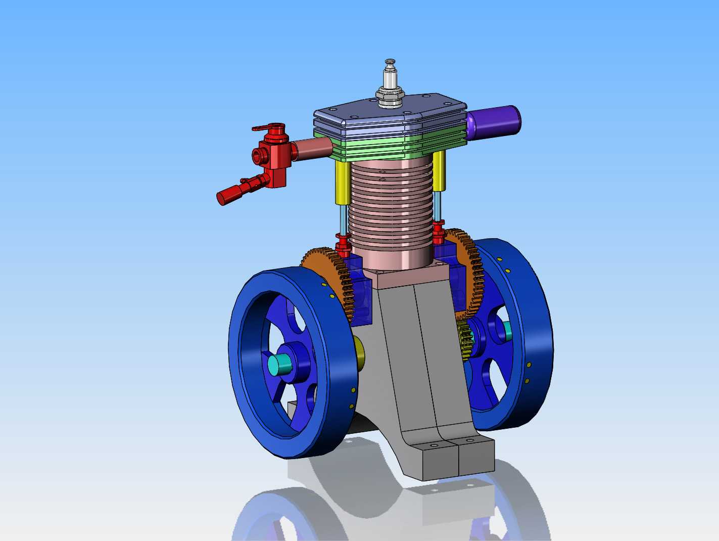
Okay---We've got a carburetor, carb adapter, heavier crankshaft and an exhaust system. Also a set of tappet guides and two very long valves, riding in valve cages. Tomorrow I will stick a set of points and an ignition cam on it, and probably a gas tank.
beEUsr.jpg
 
Don't go too fast on this one....I'm not quite done with the last one :):) I see the flywheels are the same as the last one and I hope the gears are 24 DP since I now have a gear hob for my hobbing machine.
 
I only ever use 24dp gears, because I have a complete set of cutters that size. And no, I won't be hurrying.
 
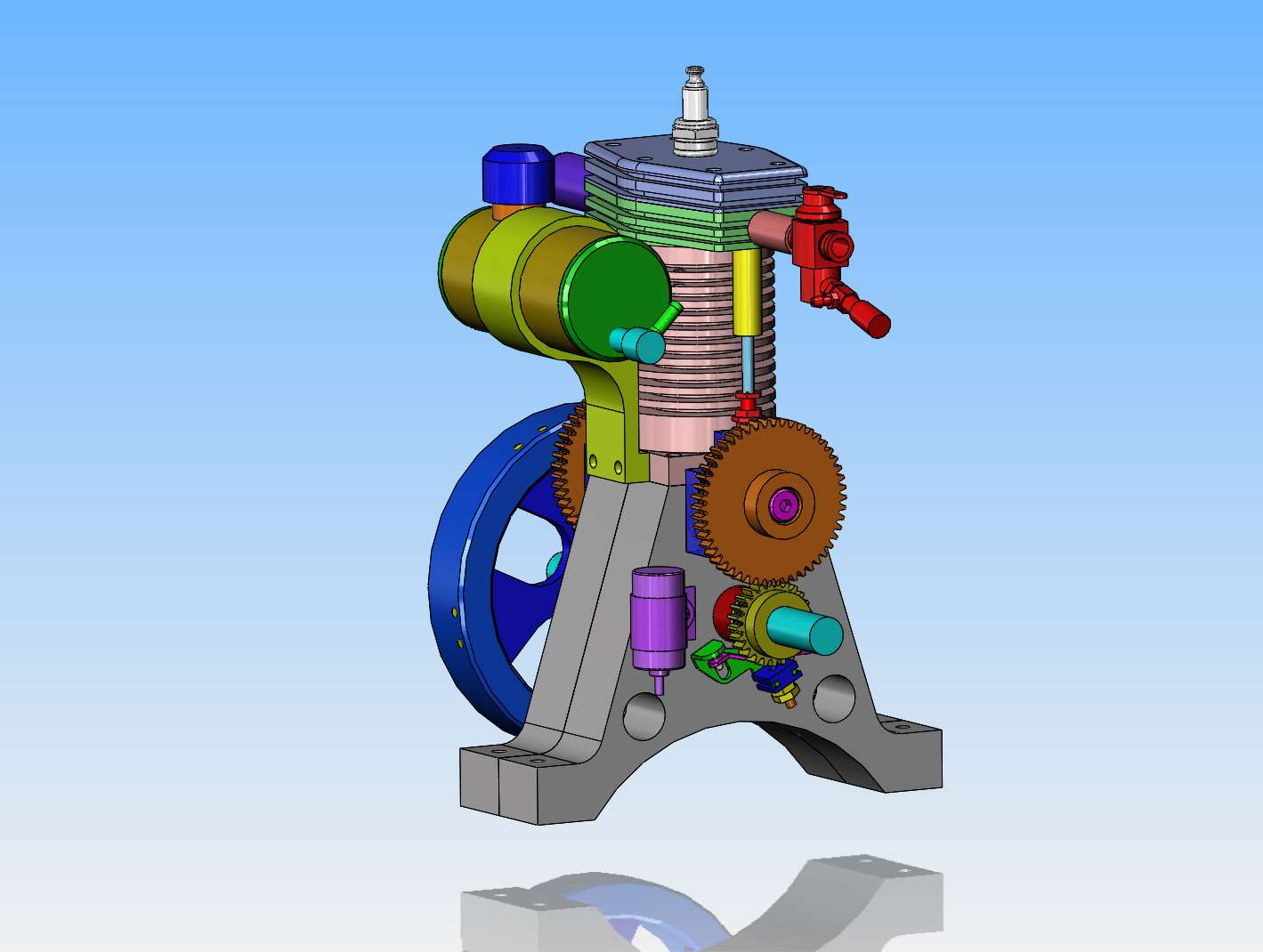
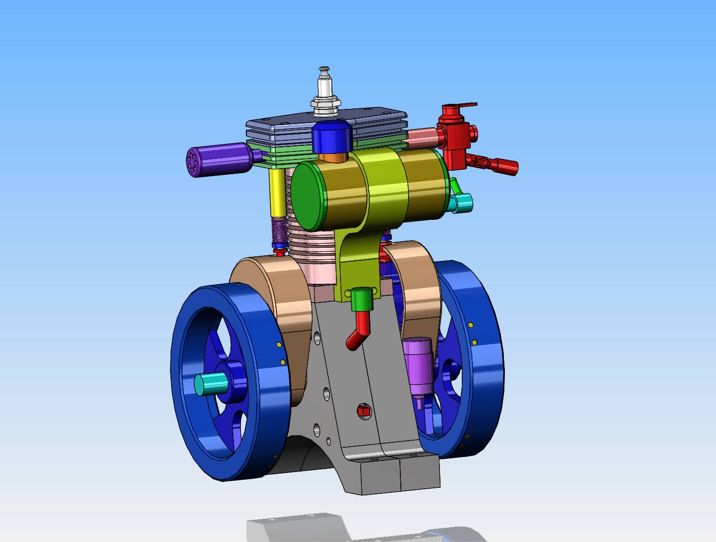
The Tee Head engine design is finished. Fortunately, I was able to sneak the ignition points and condenser in behind one flywheel (which is hidden in this model), without offsetting the flywheel any. I also added a gas tank and a pleasant looking mounting bracket. None of the detail drawings are made yet, but the design is finished, so detail drawings are pretty simple now.
RgxUR5.jpg
 
Now we have an oil filler tube for the wet sump, a drain, and some totally awesome gear guards. Other than keeping your fingers out of the gears, these gear guards cut down a lot of the noise from the gears meshing.
89Hpif.jpg
 
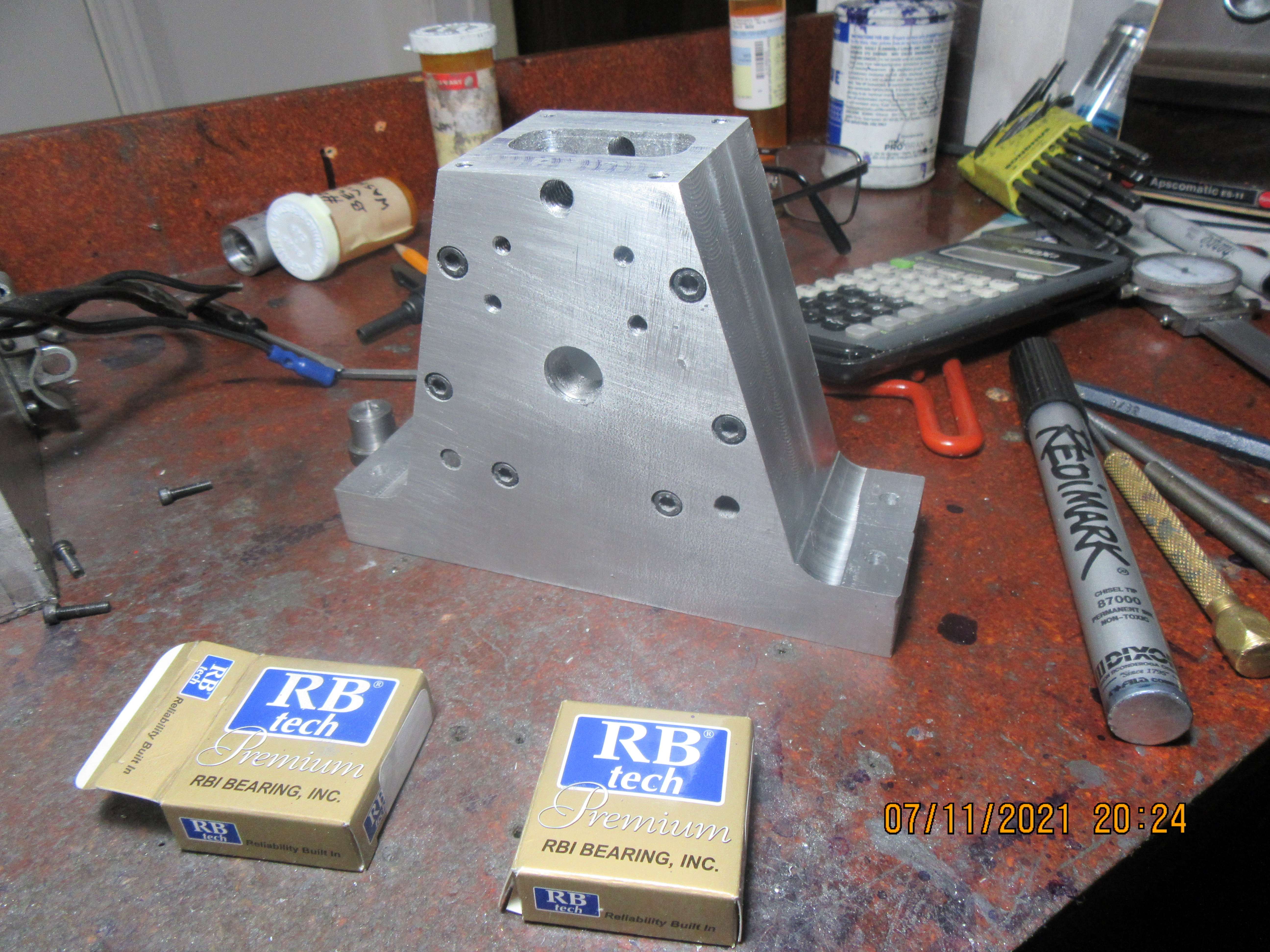
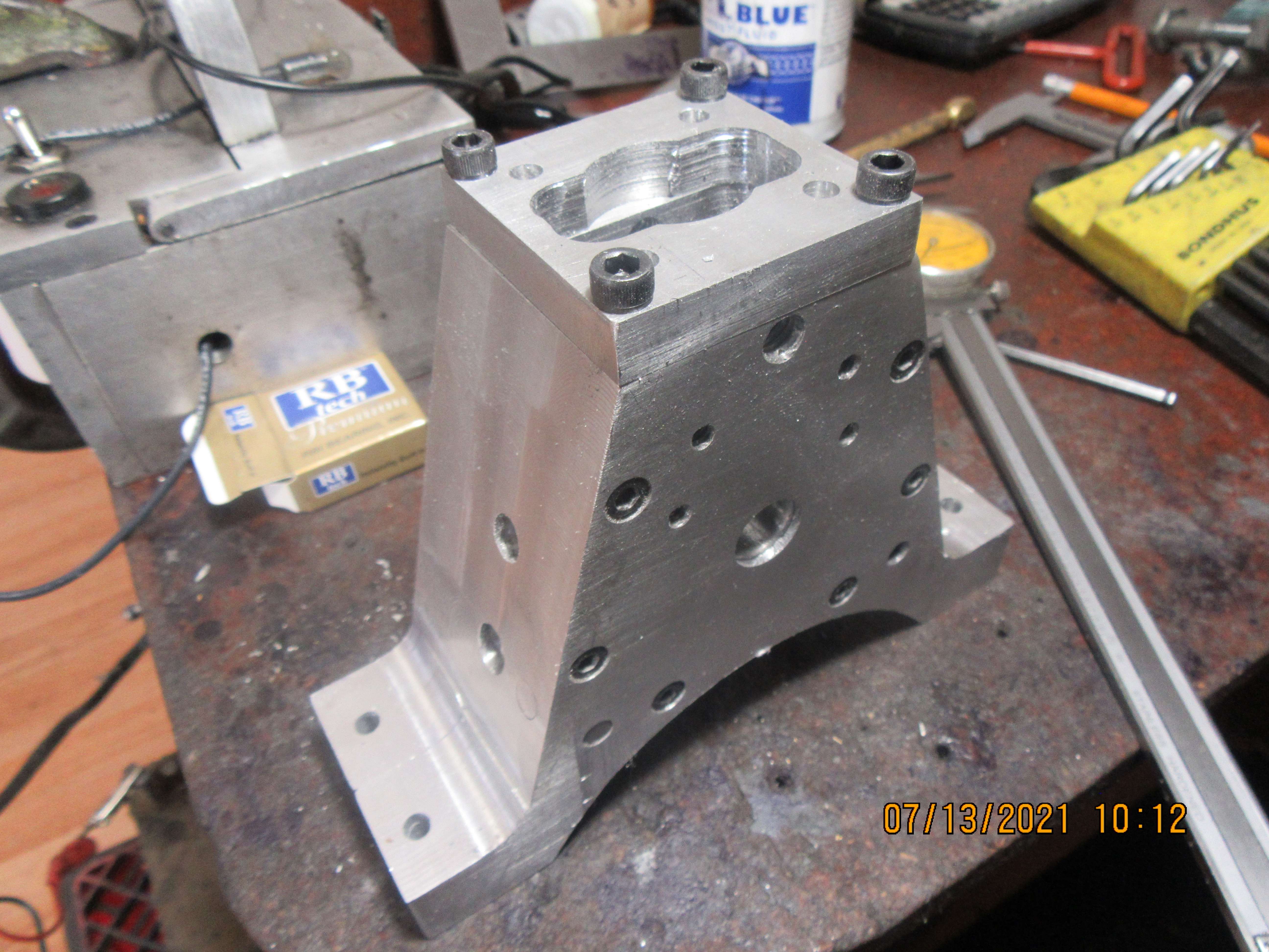
I was getting bored. Oh Oh--I'm having machining withdrawal. I haven't built anything since I made a set of rings that worked. I went and seen my favorite material guy and paid $25 for a piece of 6" x 1" x 12" long piece of aluminum. A couple of days drilling, tapping, counterboring, sawing, and milling work has yielded the main frame of my t-head engine. I have a visiting grandson from out of town, so might not machine anything more for a few days. Damn, I like a day spent in my shop!!!
J52gU6.jpg
 
You make me feel inadequate. You seem to be able to machine parts in just a fraction of the time it takes me. The parts also seem to come out looking good and without mistakes.
 
Actually I know why my projects take so long. I am too cautious and do not take aggressive enough cuts and I am too easily distracted. After so many years of having to make good time in order to make money I have finally at a point that I can just kind of diddle around. I find it very liberating and it took me quite a while to get to that point.
 
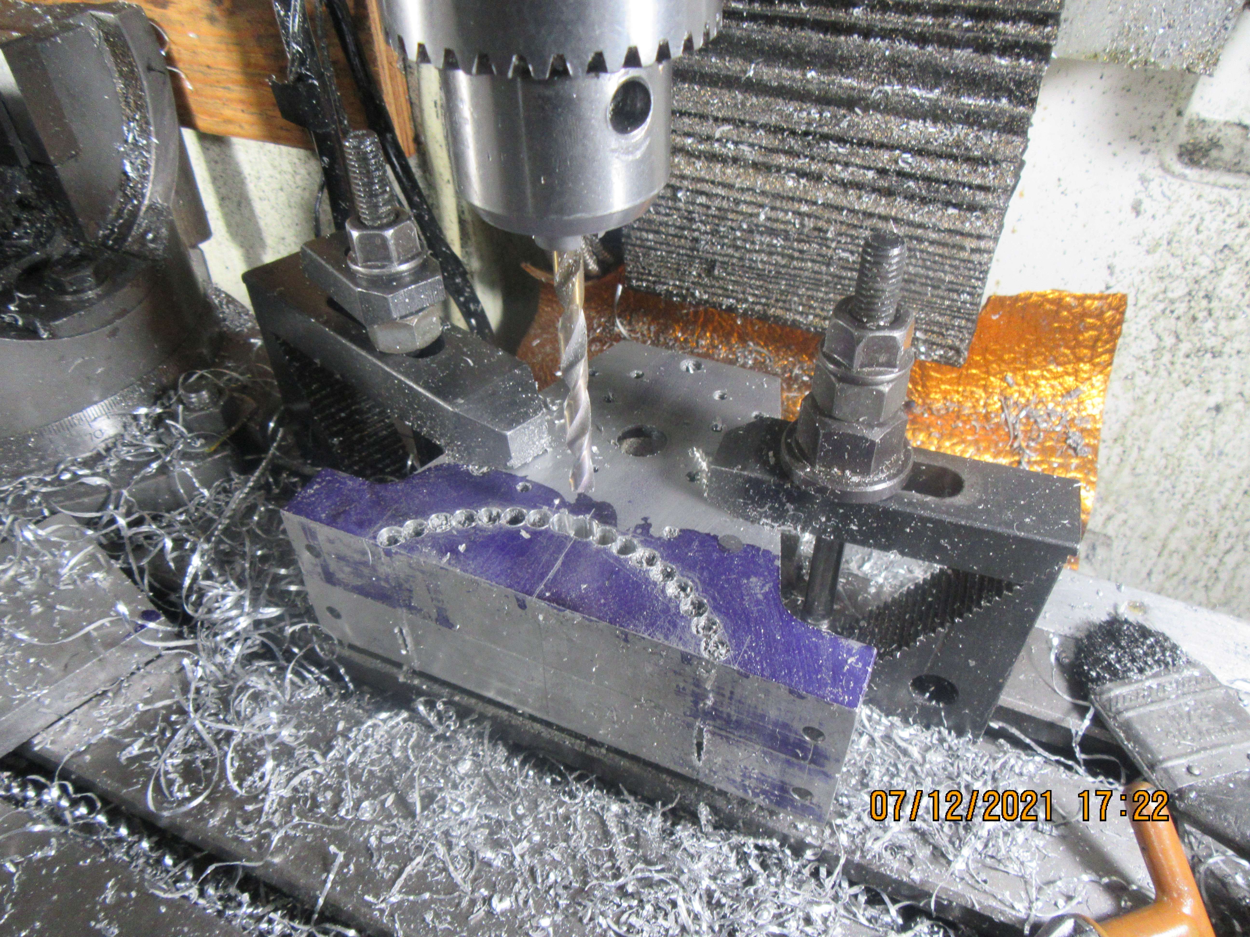
I hate chain drilling!!! The original plan was to bolt this part to the faceplate and bore it out to the required size. Sadly, my lathe which is supposed to swing 12" really only swings about 11 1/2" so, it has been chain drilled instead. Now to knock the piece out and smooth up the resulting mess. I hope that I can tie this part to my rotary table to clean everything up.
X67dwX.jpg
 
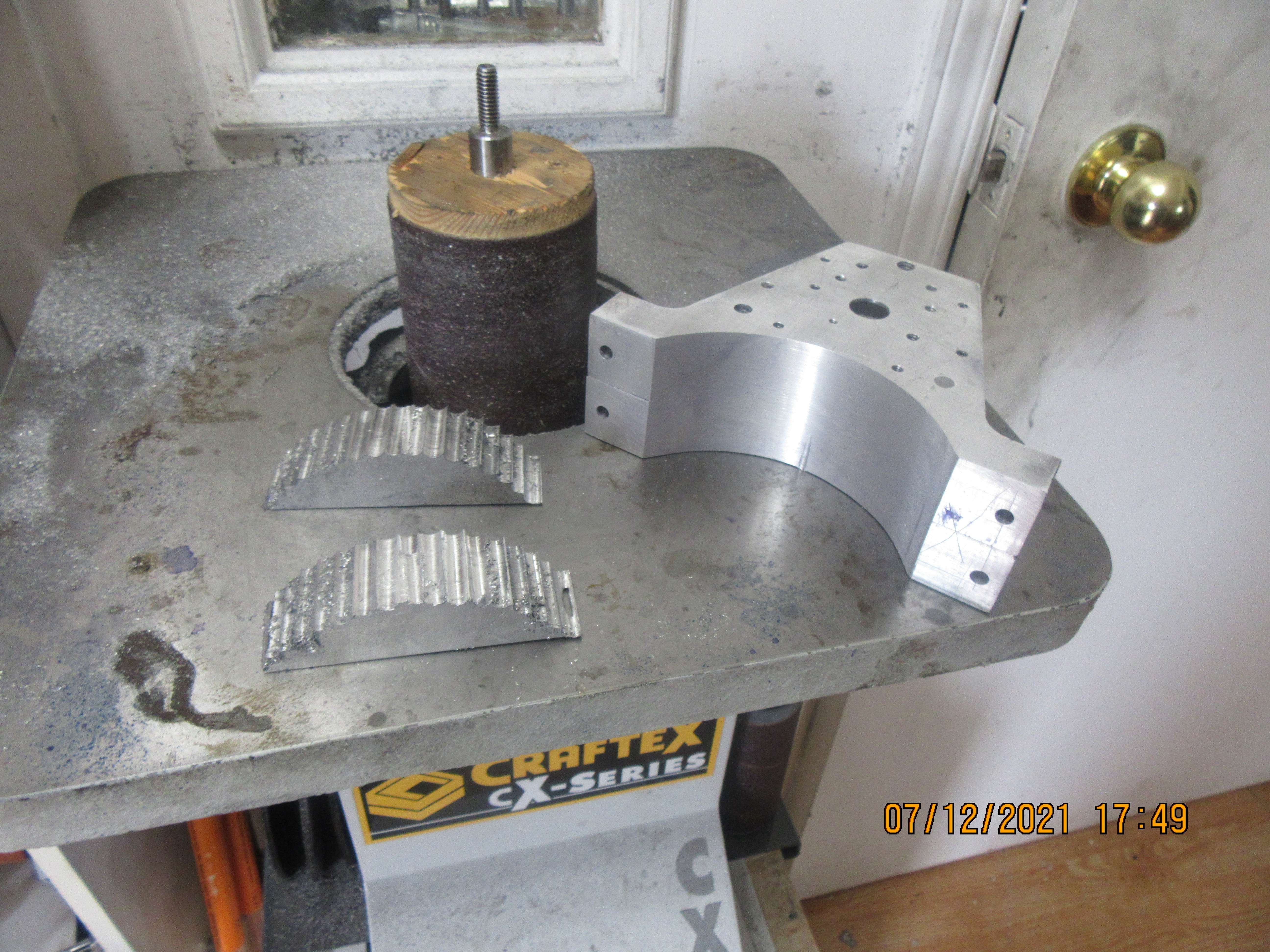
I would have had to build some more fixturing to mount this on my rotary table. This is where my oscillating drum sander really pays for itself. The curved area is non critical, just a visual thing, and this took about five minutes on the oscillating drum sander.
RGAoPs.jpg
 
No rotary table work in that at all. That was all drilled on my mill, using my DRO's. The two 1/4" holes near the bottom were drilled and reamed with the two pieces clamped together. Two dowels were inserted to lock the two plates to each other, and all holes were drilled and the profiles machined while locked together. One plate is drilled and tapped, one plate has clearance holes and counterbores. The way to do that is to put the tap drill thru both pieces. Then the clearance and counterbores are put in to the correct depth, then the hole is threaded. That way everything is a perfect match. I am a firm believer in using layout dye, and all of my holes are marked out before going near the mill. Once set up on the mill and the piece is located using my edge finder, I use the DRO's to position things. If they don't match up with what I have previously marked out, that lets me know if something is wrong before I make a mistake. If I had to count turns and partial turns of the handles it would take me at least four times as long.
 

Latest posts

Back
Top