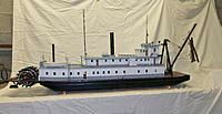
Steam engine for a sternwheeler

Home Model Engine Machinist Forum

Help Support Home Model Engine Machinist Forum:

This site may earn a commission from merchant affiliate links, including eBay, Amazon, and others.
Pete

Yes it is a bit messy but you'll also have appreciated how much better the engine sounds on steam.

It would seem to be too much oil, but in these early days too much is better than too little while everything gets bedded in. Its not like the engine is doing any appreciable work either.

I'd suggest that checking for scored bores is a bit late in the process. You're hoping not to get any scores in the bores.

Pete
 
Jyman and Pete - Ok, I feel a lot better knowing its too much oil rather than running it low. I pulled one of the cylinder covers and the bore looks fine, I would have hated to find it scored up !! I'll hold what i have for now while I keep building and adjusting and then try to cut it back once everything is completely done and broken in. What's the downside of running to much oil through the engine ? Drag maybe, this steam oil is really thick, its Green Velvet Sapon-A-Max 320 Cylinder Oil. I guess cost too because it wasn't cheap !!!

Pete - You are so right the sound in the video doesn't do justice to what I was hearing, I loved it. The mess is great too but that might be because its all new to me, I know I was grinning when I was getting hit with hot little drops of water. When I blew down my sight glass and soaked the garage door I had to do it again to show the wife and kids how neat that jet of hot water and steam looked !!
I'm hooked...
Pete
 
Well its been awhile since I last updated this thread but its because I have had to switch projects. I had to completely guy and redo our kitchen. I finished that and then had to catch up with all the other stuff that fell behind when I was workin the kitchen. So I got to get back to some time with the mill and lathe the past day or two.

I had started to work on the feed water pump for the boiler, and change out all the temp plywood parts at the paddle shaft to permanent metal versions.

The feed water pump is proof that if you start out cutting without a plan the outcome can be strange looking. I wanted a single pump that could be a hand pump and an axle pump. I wanted to be able to use the same check valves for both pumps just to cut down on making twice as many of those finicky buggers. The result is one housing that has two rams, one on each end to do the pumping. Between them are the two check valves, one to admit water to the pump and one to check the outgoing water. One ram has a handle attached to it to fill the boiler for start up and adjust the level as needed. The other ram is connected to the paddle shaft. It is driven by an normal eccentric but between the ram and the eccentric is and adjustable 'lever' for lack of another word. The lever has a center pivot point that is adjustable. The cam is connected to the lever on one end and the ram to the other end. by moving the center pivot pin towards one end or the other the stroke of the ram can be increased or decreased. I hope that makes some sense.

Due to the lack of time I didnt take many pictures of the fabrication process this time.

This video might help. The engine is under just air pressure and isnt timed very well right now and the paint can flywheel isnt on the shaft so the motion is not as smooth as it has been.

Pete

Video link -

http://youtu.be/Dg_U2GQU6hk


Pictures of the parts in random order

IMG_0013.jpg


IMG_0016.jpg


IMG_0018.jpg


IMG_0021.jpg


IMG_0022.jpg


IMG_0023.jpg


IMG_0024.jpg


IMG_0025.jpg


IMG_4696.jpg


IMG_4700.jpg


IMG_4693.jpg
 
Sometimes you just can't beat the sound of steam.


Sent from my iPad using Model Engines
 
Its time for my paint can flywheel to go.
I decided to build to paddle wheel for the engines out of solid brass rod for the weight. I found a simple ring roller design on the web here http://theatremetalwork.myblog.arts.ac.uk/2011/02/11/do-it-yourself-ring-roller/
I carved out three grooves on some aluminum round stock and then bolted all that to a previously useless vise that had been collecting dust for a long time. I was able to roll 8in diameter circles fairly easily, i was pleasantly surprised how well it worked.
Next up was a jig to solder it all up. I attached a piece of plywood to my rotary table and milled out the wheel pattern with a 3/16 end mill. I notched the ring and the spoke at each point where they attach and then milled away the center to clear the next spoke. The plan is to attach a solid hub on each side of the wheel to allow for a good solid connection to the paddle shaft. Each wheel has sixteen spokes and there will be 4 wheel assemblies. This is turning out to be very tedious. I have to use two soldering guns to get the metal hot enough to solder. I cant use my torch due to my choice of wood as the template !! The center is the hardest to heat up and it looked kind of nasty,but after milling down the center area it is fairly clear of voids in the joints. Anyway, one down three to go. The first one seems pretty flat and round looks like it will spin fairly true.
Pete

IMG_0029.jpg


IMG_0030.jpg


IMG_0032.jpg


IMG_0033.jpg


IMG_0034.jpg


IMG_0035.jpg


IMG_0036.jpg


IMG_0038.jpg


IMG_0037.jpg


IMG_0043.jpg


IMG_0044.jpg


IMG_0047.jpg


IMG_0048.jpg
 
Wow I love that idea for a ring roller, thanks for sharing it


Sent from my iPhone using Model Engines
 
This paddle wheel is turning out to be very tedious, but after lots of soldering with out good enough equipment I now have all four wheels. I turned hubs for each out of brass to strengthen up the center and give me a place to put a set screw to hold the wheel to the shaft. I mounted the wheel to a shaft in my mill and held a piece of hss in my vise to turn the outside edge of the wheel. My lathe is too small to handle the diameter. I was happy with the results, I didnt have to remove too much material off the diameter to make them true, so my ring rolling and plywood jig worked pretty well. Lots of cleanup to go on the joints ( all 64 of them ) but I mounted them up for a test look and spin. Now I have to figure out a way to mount the paddles to the wheels. This is where planning ahead might have helped !
Pete

IMG_0004.jpg


IMG_0003.jpg


IMG_0005.jpg


IMG_0009.jpg


IMG_0014.jpg
 
Here is the progress on my steam engine setup.

I was having trouble making enough steam to keep up with the appetite of the two engines with the boiler I built long ago. It was built with the thought of a much smaller engine. Making another bigger better boiler isn’t an option so I went the route of throwing more heat at it. I built a stainless steel box around the boiler and insulated the inside with two layers of ceramic insulation. This allowed me to add a second burner under the boiler along with the original that dumps its heat down the flue pipes. I added several feet of copper tubing between the burners and the boiler shell inside the stainless box to make a better superheater. The steam is now hot enough to melt the first soft solder joint that was in the plumbing about 6 inches downstream to the engines. It was interesting when it gave way; tiny balls of solder are stuck to everything near the failed joint! A side benefit of the elevated steam temp is that it seems to be much dryer so the problem with condensation in the cylinders has been reduced. I still want to cover the top of the boiler with some kind of wood planking just for decoration over top of the ceramic insulation. I don’t have any construction shots of the boiler just a few of how it sits today. It now can build pressure the all the way to the relief valve while the engines run! It looks like the fuel burn rate is about 4oz of propane in a half an hour.

IMG_5050.jpg

IMG_5051.jpg

IMG_5052.jpg

IMG_5053.jpg

I bought a steam attenuator from John Hemmens in England to keep more control over the burners and the boiler pressure. I want to be able to float this setup in a boat and not have to worry about what the boiler is doing while it is out on a pond. Next up will be plumbing that into the system and getting a remote control fuel shutoff and throttle setup.

IMG_0063.jpg

The engines now have the ability to shift to reverse. I came up with a setup that uses a couple of short arms on a torque shaft that shift the valve cam linkage from the upper pin or the lower pin on the valve cranks of both engines at the same time. I bought a landing gear retract servo for my remote control setup and it seems to work well. I have done test runs shifting from forward to reverse while running on compressed air and I don’t see where running on steam will make any difference, so that takes care of another hurtle.
Just a side note the camera really points out how dirty the engine has gotten doesn't it !

IMG_5031.jpg
IMG_5040.jpg
IMG_5046.jpg
IMG_5047.jpg
IMG_5048.jpg
IMG_5049.jpg

Here are a couple of shots of one of the cams mounted and the cam follower brackets. I bonded teflon tape to the surfaces the cam rubs on to try to cut down friction and wear. It takes a lot of force to open the valves and the cam shape moves the open very quickly. All that effort was effecting the motion of the paddle wheel, making it speedup and slow down during low throttle settings. I expect to run the paddle in the 40 to 100 rpm range so it needs to be smooth, but that will ultimately depend on how well it moves the boat.

IMG_5043.jpg
IMG_5044.jpg

I am real close to calling the paddle drive system done enough to start building the boat it will go in and that doesn’t really fit into the category of this forum. I want to go back through the engine to clean up some of the parts that were completed to the point of working well but not as pretty as they could be and then polish everything up to a shine. I will post a final set of pictures when it is all done someday, but that’s a long way off.

My ultimate goal is to drag this engine and the boat it will go in to a machinist show!! It won’t be as nice as the artwork I see other create, but it’s still kind of unique. I have only been to one show and that was Cabin Fever a couple years ago and I loved it. It will be a long drive to bring something there but I think it would be fun !

Pete
 
Oops I forgot to put the video link of the linkage running on the last post so here it is.

Pete


[ame="https://www.youtube.com/watch?v=WlHmj02_Z3I"]https://www.youtube.com/watch?v=WlHmj02_Z3I[/ame]
 
Last edited:
Thanks Ron,
Unfortunately I wont be able to make it to Cabin Fever this year it will have to be next year. :(
Pete
 
Amazing! With compliment and thanks for sharing.
 
Sorry you wont be at Cabin Fever, I would like to see that engine.

Is it a scale model of a real engine or your own design? The reverse link is something I have never seen before. It looks like a very clever arrangement.
 
The engine is based around the lever engines of the western river sternwheelers in the 1800's. I just looked at exterior drawings and worked out an arrangement that I thought I could build with my skill level and the materials I had around and the capabilities of my Chinese mill and lathe ( which are more than mine ) . So I guess it’s my design but it operates and looks a lot like those engines. Here is a link to some of what I used http://www.alaska.net/~rmorris/steamboat1.htm
You can see the reverse linkage but its partially covered up by a guide plate.
I also bought a book called 'smoke ash and steam' from these folks http://www.islandnet.com/~westisle/History/horizeng.html
Those gave me the info to build what I have. The coaxial shaft setup of the rockers was hard to understand how it worked from just those drawings.

I didn’t design in any cutoff for my engines like those drawings have in them, I am not too concerned about steam/fuel conservation at this point. Maybe that would be a modification someday.
 
Well I have been unhappy with the performance of the first set of boiler steam pressure relief valves that I made so I went looking for a good design to use to make a more reliable set. My design works but they just start dribbling more and more as the pressure rises, and as they let out steam they just sort of close. I wanted more of a pop action and a little reading told me my design was all wrong. I have made most of this steam engine up as I have gone, now its time to let someone else's design and wisdom fix my problem. I didnt want to reinvent the wheel so I went with a design by this guy http://sparetimelabs.com/animato/animato/3003/3003as.html
I liked the design because it allows for the adjustment of both the relief pressure and the reset pressure. I had to convert everything to inches and set the proportions for a .250 stainless steel ball, which is what I have lying around. I have them set with shop air so far and they work well. One is set for 40psi and it drops about 5 psi before closing and the other is set at 45psi and drops about 5 psi also. I will adjust them under steam later. They are a little big but they wont be seen when the ship is built anyway and too big is better than too small when talking safety valves.
Here are the shots of how they came out I didnt shoot any chip making pictures this time, thats hard to remember sometimes when I just sneak into the garage to whittle at metal for a short time when no one is looking for me !!

Pete

IMG_0064.jpg


IMG_0065.jpg


IMG_0066.jpg


IMG_0067.jpg


IMG_0069.jpg


IMG_0070.jpg


IMG_0071.jpg
 
Here I go into uncharted waters !:p
I have never built a boat of any kind so why not start out over my head. I wanted to build a boat that looks similar to the sternwheeler down in Disney. It was built to represent the look and feel of the riverboats of long ago. I figure it would make a good subject to use as a pattern for my attempt. Another benefit is my wife is more supportive of it because it means a ' research trip ' to go see the details.

I started off with a little drawing on my custom graphite 2D design system.
IMG_0074.jpg
Once I got a rough outline of what I wanted I scaled it up to the size needed to support the weight I anticipate it will be. I am just making a wild stab at the 50lb mark but who knows. I never did this before. I need a weight to figure a waterline to set the paddle depth which will determine the deck height !! If I guess wrong I can ballast it if I am too light. If its to heavy then it will be surgery I guess. After the big drawing I started cutting foam for a mock up. I use the 1/4 inch blue fan fold stuff from Lowes. Its a lot cheaper that wood and easier to make changes. The first build up looked short and fat, so I added some length to the hull in the middle. That helped but it was still funny lookin. I added more to the bow, but that takes it to a length that wont fit sideways in the back of the minivan ( ugg now its either haul out the truck to go float this thing or pull a seat out of the van )
IMG_0075.jpg
IMG_0076.jpg
IMG_0077.jpg
IMG_0079.jpg
IMG_0081.jpg
IMG_0082.jpg
IMG_0083.jpg
IMG_0087.jpg
Anyway the look was still not right but looking at images of the real boat closer showed me that the sides of the upper decks lean inboard. I cut down the floors of each deck to get the right lean and now its getting better. I have a lot more adjusting to do, but progress is being made, I think. The top deck in these shots hasnt been cut down yet. I want to finalize almost everything in foam before going to wood and fiberglass. I think it will take awhile.
IMG_0088.jpg
IMG_0089.jpg
I should have built a smaller steam engine. It will be way way out of scale for the hull, but I doubt anyone will care, I know I dont. I just want it to float and propel itself with steam and not catch fire, explode, and or sink !!:)
IMG_0090.jpg

Looks like my dining room table workbench is about outlasted its welcome too, so I will have to clear off the work bench to continue.

Pete
 
Pete

Think about increasing the hull length. River boats tend to be long and narrow with shallow draft. As it looks now to my eye it is to tall for the length you have.
Here is a photo of Mikes W. T. Preston. It is not a mississippi river boat but you can see the length, width, height ratio.

Dave

 
Dave,
Yep your right but since I didnt plan ahead at all I am forced to keep the width at least 16 inches to fit the engine and boiler as built. The length is already 55 inches which is making it really big. Much bigger and dealing with transporting and storage will be a problem. Also the boat I am using as a pattern isnt that far off, I dont think. It might be a little unrealistic to the real riverboats but it does exist and it is a real full scale boat. I tried to get Disney to send/sell me a few drawings of their boat but all I got was the telephone number to their legal dept !!
Here is what it looks like

Liberty Bell River.jpg
Liberty_Belle_Riverboat_by_hyku.jpg
liberty-belle-sailing-rivers-of-america-1-9.jpg

Do you think I am way off in my rough draft ?

Pete
 
Pete

Do some displacement figures and keep the super structure as light as possible. Are you planning an open superstructure as we see in the photos. That way they will be able to see the boiler and engines with the superstructure in place.

Dave
 

Latest posts

Back
Top