Slightly Loco

Home Model Engine Machinist Forum

Help Support Home Model Engine Machinist Forum:

This site may earn a commission from merchant affiliate links, including eBay, Amazon, and others.
Yeah, I considered pressing them for as long as it took for me to realize I had no suitable pressing device ;D
 
One more question for now(there be a lot more later ;D) Where did you get your pipe for the flue?
 
The flue pipe is ordinary 1/2" copper pipe. I had some hanging around already, although it's available in short lengths at the hardware store or better, piping specialists where I had to go for 1-1/4" by the foot anyway. Ordinary plumbing pipe reportedly isn't so good in larger size boilers, but at these sizes and pressures, it works ok. The heavier wall varieties especially.

I also made the boiler mounts. The plans show some sort of wooden material. Originally I hacked some mounts out of wood with a hole saw for mocking up purposes, but I decided to upscale for real and made them from some brass rod. This will be a lot worse for heat-transfer, but efficiency isn't at the top of the list for this engine.

Take some 7/8" rod, clean it up a little in the lathe and drill for a convenient tapping size if desired. Move it over to the mill and setup a boring head to cut the desired diameter. Bore down, move over. Repeat until the 'half-hole' is the full width of the rod. If it doesn't fit perfectly, tweak the boring head until it does. Back to the lathe, part off and done. Notice that the picture shows a tactical error with the boring head setup-- from that side all the chips spray straight at you. It's what I get for being lazy and not wanting to move and re-tram the vice. ;)

[Edit: thinking about it some more, it might be worthwhile to bore out the rod to just over the curve depth while it's in the lathe, leaving only a small rim to curve. Heat transfer would be reduced with less surface area in contact with the boiler and the air pocket could be packed with insulation if really desired.]


boilersupportboring.JPG


boilersupports.JPG
 
Thank you again. I don't have a problem finding plumbing pipe. I'm a plumber by trade so I have all that stuff lying around.
Thank you again.
John
 
Spent most of the morning dinking with the gear train. Turns out when I redrew the plans for the gears I had available, I didn't leave quite enough play in the train and it would jam up periodically. Once I figured that out, I was about to make new side beams when I decided to try an offset bushing on the center gear to see what that did. I had to make 3 sets of bushings, but two thicknesses of Dr Pepper can (0.008" or so) on one jaw in the 3-jaw was just about right. You can't even tell by looking at it that it's offset, but just that much clearance did the trick.


geartrain.JPG
 
After a morning of nothing visible to show for it without a pair of calipers, I started on the bodywork. It's just sitting on there for now, but at least it's something new to look at ;)

Here's a teaser with my LegoTM guy working out where to put the plumbing.

BodyWorkTracks1.sized.jpg
 
Got most of the bodywork anchored. The roof is still loose until I sort out the burner and gas tank. The plumbing is mostly complete. There's still a lot to do before I can steam it, but here's the Loco getting ready for a test run on air.


AirTestRunSetup.JPG
 
It's looking great Shred. I like the shot with the lego man, it gives a sense of scale.
Do you plan to use the cylindrical gas tank from the plans or a hidden rectangular one like tony bird did?
Are you modeling your body work after a particular engine, or is it your design? I think the roof gives it a cleaner look than having the top open.
 
Macca said:
It's looking great Shred. I like the shot with the lego man, it gives a sense of scale.
Do you plan to use the cylindrical gas tank from the plans or a hidden rectangular one like tony bird did?
Are you modeling your body work after a particular engine, or is it your design? I think the roof gives it a cleaner look than having the top open.
Thanks. It's a little big for Lego-scale. I suspect it'll be a little warm in for him in the cab under steam too. I'm not sure about the gas tank yet. There's not a lot of room left anywhere, but it won't run long on one fill of water. Some ideas I've had include the front footplates and under the cab roof as well as the usual spots.

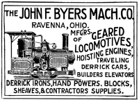
The bodywork is entirely freelance-- I'm aiming for an 'American' look like the original Byers, but more enclosed and with a healthy dose of wacky/fun/toy look thrown in. The kind of thing I imagine running circles around the bottom of an X-Mas tree.

advert_engineering_news-t200.jpg

 
Got the safety valve built tonight before it started snowing (that's a rare enough event I had to grab the camera and go document it).

The original plans have no safety valve and rely on the wobbler spring opening up and dumping excess pressure. I wanted to put in a real safety, so I stacked the filler and steam dome and made a safety for the front boiler bush.

I ended up using the safety from the Idris plans, except I modified almost all the dimensions ;). It works very nicely on air, popping off and on with great regularity and should provide plenty of flow for this size boiler. I considered making it in the form of a whistle for a few minutes since it does resemble one, but sanity prevailed. ::)

The only tasks remaining are to build the burner and gas system and fix the roof (plus a whole lot of finishing work). It's looking like a loco now!

withsafety2.jpg
 
Shred,

This is amazing.
wow.gif


I admire how you work at such a small scale. :bow:

Best Regards
Bob
 
That is really beautiful. Did you by any chance take pictures of the build on the safety valve?
That looks like a good idea.
John T.
 
I don't have many photos on the safety valve construction, but here's one of silver-soldering up the valve stem and the Idris plans page with my scribbles on it from changing things around.

It all started because I didn't have a 1/8" stainless steel ball; the nearest size on hand was 5/32" and thus the changes cascaded. I made the retaining plug and top to be 1/4-28 threaded and 3/8" OD vs 1/4", the spindle was made from 3/32" brass rod with a .20" cup on the end (made from running a center drill lightly into some 1/4" stock, drilling to 3/32" and turning down to .200-ish, cut off and carefully silver solder on). The base was threaded to match the boiler bushes and made from 1/2" brass because those are 3/8" threaded. Instead of longitudinal slots and recessing the retaining plug, I made it solid and slotted the top for a screwdriver ('security' screwdriver bits work well for this). Since I then needed another steam escape path, I drilled six 1/16" holes around the top, using my 5C hex collet block to index them.

[Edit: if you see the safety-test video below, you might want to reconsider side-vents. That effect would be pretty cool vertically]


IdrisSafetyMod.JPG
 
If you like I'll send you a drawing of one I have used on a my past project and I'm using for the next..
Cheers
Paolo
 
After much gnashing of teeth and pulling of my little remaining hair, I finally got the loco engine running on steam from the boiler. It wasn't nearly as easy as I'd thought, given as how it ran pretty well on air already, but the tiny boiler requires closer tolerance work than an air hose, so I wrote up a few commandments for those that might follow.

  • Thou Shalt Have No Leaks - even the smallest leak causeth woe and loss of pressure
  • Thy Wobbler Faces Must Fit and Be Flat - if thou canst see light between them, thou must continue lapping
  • Thy Wobbler must run well on 5 PSI Air- mayhap thus 15 PSI steam willst then function
  • Thou Shouldst Rig a Pressure Gauge - else the mysteries of non-function will abound and multiply

:big:
 
Back
Top