rodw
Well-Known Member
- Joined
- Dec 2, 2012
- Messages
- 1,146
- Reaction score
- 341
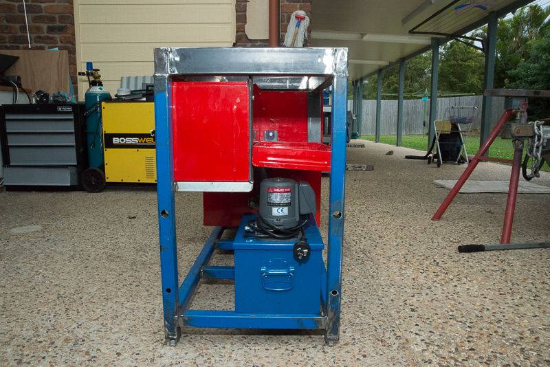
I used 35 x 35 for the legs because it married up with the 35 x 65 RHS. 3mm thick RHS is heaps. I think I used 2.6mm wall thickness.
My bottom rails are off the ground a bit which when the adjustable feet were added, gave me plenty of room to get the toe of my boot under so I could stand hard against the lathe.
Maybe I'm paranoid about stability given this was the driving force for me to make a lathe stand

I'd keep the bottom rail attached to the front legs rather than recessed in like you have.
The reality is that at 280kg, the lathe is only adding 70kg load per leg which is nothing in the scheme of things.
If you have your heart set on mounting the lathe to laterals, why not use two 65 x 35mm RHS rails on each side of the lathe (eg. below the mounting holes) that are joined together with a few spacers of the same material like a ladder.
I'm not convinced the so called "torsion bar" design adds any value v's a well designed and constructed conventional stand. For starters, it is using the RHS beam with incorrect orientation. (eg. Long edge should always be vertical to attain maximum bean stiffness).
If you sketch out where the forces are, they will be downwards at the lathe mounting points with equal opposing forces upwards at each leg regardless of how its mounted. So then you end up with bending moments between the stand legs and the lathe mounting points.
My bottom rails are off the ground a bit which when the adjustable feet were added, gave me plenty of room to get the toe of my boot under so I could stand hard against the lathe.
Maybe I'm paranoid about stability given this was the driving force for me to make a lathe stand

I'd keep the bottom rail attached to the front legs rather than recessed in like you have.
The reality is that at 280kg, the lathe is only adding 70kg load per leg which is nothing in the scheme of things.
If you have your heart set on mounting the lathe to laterals, why not use two 65 x 35mm RHS rails on each side of the lathe (eg. below the mounting holes) that are joined together with a few spacers of the same material like a ladder.
I'm not convinced the so called "torsion bar" design adds any value v's a well designed and constructed conventional stand. For starters, it is using the RHS beam with incorrect orientation. (eg. Long edge should always be vertical to attain maximum bean stiffness).
If you sketch out where the forces are, they will be downwards at the lathe mounting points with equal opposing forces upwards at each leg regardless of how its mounted. So then you end up with bending moments between the stand legs and the lathe mounting points.


![DreamPlan Home Design and Landscaping Software Free for Windows [PC Download]](https://m.media-amazon.com/images/I/51kvZH2dVLL._SL500_.jpg)


