Setting up Shop Questions - from an NZ learner

Home Model Engine Machinist Forum

Help Support Home Model Engine Machinist Forum:

This site may earn a commission from merchant affiliate links, including eBay, Amazon, and others.
You might find it better by searching for a 68 grade SLIDEWAY oil.

These are maybe a little different to other grades of 68 oils as they will have additives that keep the oil in place.

A slideway oil is designed to give a permanent thickness layer to prevent metal to metal contact on all your slideways, and as far as I can gather it is about 0.002" thick. Without that layer, your gibs might seem to be a little loose, and further adjustment to take up that slack can be causing undue wear. Lube up first, then adjust your gibs until tightish, then continue to lube every day if needs be.
I did this on my mill well over six years ago when it was first commissioned, and the gibs haven't been adjusted since.

In all honesty, I grossly over lubricate my machines, and it drips all over the place rather than the 'polish it until it shines brigade', who may be doing more harm than good.

Having been a mechanical type of engineer all my working life, I have a ruling that a few pounds spent on the correct lubrication over a couple of years is better than having large amounts of wear on your machine if it isn't lubricated properly that could cost hundreds of pounds in replacements. Paint layers are only cosmetic and if needs be they can be cleaned up or repainted, layers of slideway metals can't.

John
 
I note your tape is in inches too.
I do not know NZ also used inches:eek::eek:

attachment.php


Dave

View attachment 84210

Hmm 1.2m long. not too bad.
View attachment 84209

Nice big solid 200mm 4 jaw and 200mm plate.
View attachment 84211

View attachment 84213

.

Cheers,
J.
 
Dave - NZ is officially metric and in all honesty the bulk of everything is metric. However so many of the plans out there for model engineering are all imperial I have made sure some of my measuring gear can cope with metric and imperial. Hence the inches on the tape measure. I have the same situation on a couple of metal rules as well.

I'm still tossing up re what to do on micrometer front. Digital which gives me dual system but at a hefty price or two traditional mics covering both systems.

Cheers,
J.
 
I was brought up on imperial then graduated to metric in drawing office and works.Fortunately I can work in both.I prefer to work close tolerances
in thous of an inch which I can see in minds eye but late and mill are both metric.As for for mikes and verniers digital is the only way to go
 
J,

I use everything under the sun for measuring, both digital and manual, for both internal and external.

Now to upset the Mitutoyo et al stalwarts who will have you spending hundreds of bucks, which you don't want to do when first starting out.

Don't be afraid of buying a cheap Chinese manual set of external Mics. I did, a set up to 4", for use when starting and half half way through a job, then I was going to switch over to the expensive stuff for finishing off.

If you are confident enough to strip them down, clean them out, lubricate and adjust to a nice personal feel, and calibrate them with the supplied gauges (all very easy to do, and the tools to do it are usually supplied), then you should find that they will do everything you ask of them. I did, and they are still spot on after a few years service, so much so, I now use them from start to finish. All for the cost of one digital, and mine have tungsten faces as well. I still use my digital ones, but mainly when I am grinding, as they can work to much finer tolerances.

Something similar to these

http://www.amadeal.co.uk/cgi-bin/sh...chet-Stop-Type-AMA_MT_600_C304TD.html#SID=213

Be very careful if you go for digital ones, make sure they are electronic, not the click over ratchet types with numbers changing in a small window, very expensive when I started to use them in the early 80's, very old hat now.

John
 
Last edited:
Cheers gents and good to know John re the ability to get good service out of "cheap" chinese sets.

I'm now pushing ahead with the lathe stand design and as I feared the more I think about it the more complication I'm probably adding in. Oh well, having fun.

Anyway the challenge I saw when looking at the lathe, how the chip tray is positioned under it and where the center of weight would end up being on the stand was that there would be material weigh forward on the stand. Not good when ideally I don't really want to bolt it down until I am confident in where it will be placed.

So I came up with this kind of concept. By using angled front legs I get a wider support footprint making the weight of the lathe sit more centrally in that support footprint. These images dont have any cross bracing on the legs yet, its more initial concept stage. The intent is for the green bars to be 100x6mm SHS, two runs welded together to create a single 200x100mm beam for the lathe to sit on. It has a foot pad size of 180mm wide. I'll be modeling in the drip trap in a later render.

The red legs are planned to be made from 75x50x3mm RHS. I expect to do some bracing between the legs using either the same box section size or perhaps 30x3mm SHS.

Ideas, thoughts welcome.

Cheers,
J.

LatheStand001.jpg

LatheStand002.JPG
 
I agree with both Barry and John but whilst I have electronic stuff in both formats, I have a huge set of mikes and verniers made in Imperial and obviously mechanical. One adjustable one will 'bridge' a foot. Of course, I have a set of 'J' blocks and a packet of cigarette papers! Strangely, most were very second hand- and cheap. Clocks- galore!

I've got a Columbus gauge and a vernier which can be boiled:eek:

Most people get by with 0-1" and a cheap dual vernier. Eventually buy to suit YOUR specific needs.

Norman
 
On the measuring front I do have budget digtal calipers. 150mm and 300mm (used when building 3D Printer). Hopefully that will help for the intial starting point. As you say Norman, I will need to figure out what makes sense for what I am making.

Cheers,
James.
 
What you must remember is the fact that you are not standing at a machine making the same damned part from the day you started work to the day when you go home from their for the last time, you paint the kitchen and then sit down- and die.
Unfortunately, that is the lot for many. You will be making 'one offs' and really have little to do with some quality control inspector with his mind set on ensuring that nothing falls outside of 'three standard deviations from the norm'

Hint, I gave my 'guessing stick' away millions of light years away and was far too young 31 years ago to join the 'walking dead' and patiently awaited 12 times 31 'pension' cheques going into the bank ------so far-So good!

This is a hobby- a nice one provided that you avoid the sad ranks who think standing all day at a machine qualifies them -for something which I never discovered.

Go make things- your way, learn, sometimes succeed, sometimes fail- but keep the dreaded senile dementure, hopefully at bay.

There are precious few who have lasted long enough to form such views.

Your next project should not be how to make a stand to put a lathe on or what sort of mike to buy, it should be how to make your own 'Luck' and I hope that you succeed.

Norman
 
For me since this is soo far removed to what I do as a day job even the experience, process of designing and the learning achieved from building the lathe stand is an adventure.

For many it probably seems to very mundane. But for me its quite interesting and challenging to get the best result I can while learning as much as I can.

J.
 
The lathe table design continues. Bit of a render as an update.

Screen Shot 2016-09-25 at 9.30.42 PM.png
 
The lathe table design continues. Bit of a render as an update.

I'd be a bit concerned about the forward angled legs getting in the road not to mention the additional build complexity of mitred corners that are not at 90 degrees. You'll need to jig it up to get the angles right. The last thing you want is a tripping hazzard around the lathe. If you are building to the drip tray dimensions, it will be very stable with upright legs. Aso consider adding levelling legs. M12 bolts on each will hold the weight easily when you look at commercial offerings.

Nothing wrong with butt joins and welding on endcaps which when ground back won't even be noticed. It will be much simpler for a starting project.

I'm ok with the mitre joints to get a final 90 degree angle, did those all for my welding cart. The "complex" front ones have been worrying me. I have a variation which is more traditional that I'll post up once I finalize it a little more.

yes plan is to go to drip tray dimensions. But I live in an earth quake zone and we do have a few shakes every year. So I am being a bit paranoid around stability. I might just have to accept I need to dynabolt it to the floor and be damned about moving it.
 
the straight leg version. Not got all the bracing that could be there but it gets the idea across.

Screen Shot 2016-09-26 at 9.12.01 PM.jpg
 
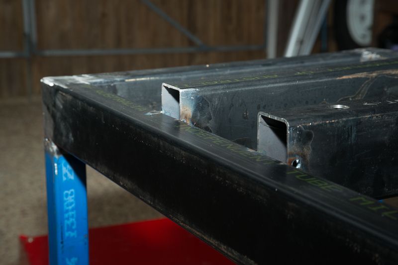
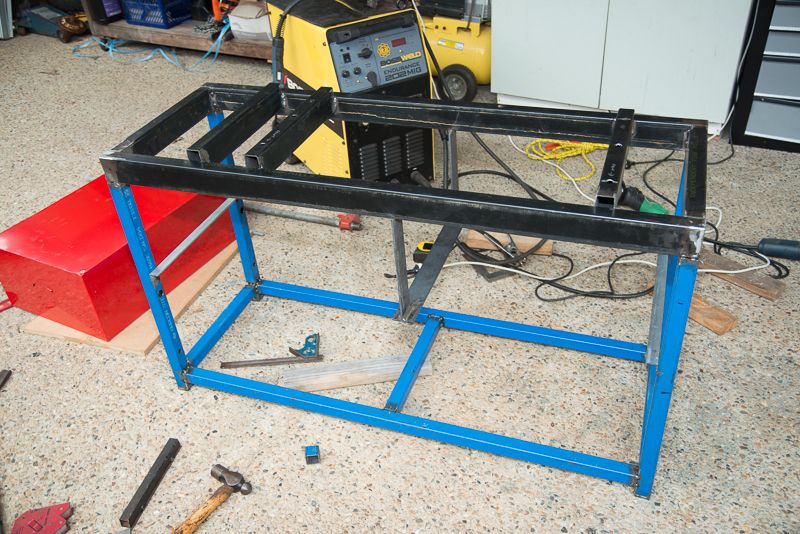
I like it better, Just remember that the surface of the drip tray is above the lip. I set the mounting crossmembers a bit higher than the frame

DSC_2994_zpsa93e9eac.jpg


DSC_2988_zpsb89a5cf8.jpg


The headstock end only bolts to one of the crossmembers.
 
I would move the front bottom 1200 lg member inboard to give more room for your feet when leaning over the machine
You have improved in leaps and bounds since you started the threads
I think you will need some longtitudenal bracing in the form of gussets,or cross bracing
Maybe best would be say a rear panel to form a diaphragm

I've been looking at cost of steel and plan to redesign a bit tonight based on using less of the large stuff and having the bulk of the framing using either 35x3mm or 40x3mm SHS. This should take some weight out, still be plenty strong enough and drop the cost quite a bit.
 
40 40 x 2.5w rhs for the legs and 40x25 rhs fpr the horizontals
would be adequate.With 1.5mm thk shts pop riveted to ends and back
would stiffen everything up
 
40 40 x 2.5w rhs for the legs and 40x25 rhs fpr the horizontals
would be adequate.With 1.5mm thk shts pop riveted to ends and back
would stiffen everything up

Thanks. Given how this will be located I will have access to the back and intend to use the back side of the stand for metal storage. So want to keep that open.

Good to have a view on the adequate sizes. I'm still getting a feel for how much steel is enough. :)
 
Another go a this. I still need to see if I can source the 100x6mm SHS via scrap. if not I might need to revert to Rod's design, else crank open the wallet. Which would be absolutely fine. :thumbup:

I'm just kinda keen to do this torsion beam design.

Anyway, doing this with some cheaper 40x40x3mm steel for the legs and bracing. There is probably some more bracing I will add, gussets bracing the back frame for example. But it's pretty close I think. Just need to sort out what hight to set it at for good ergonomics. I seem to recall something about the forearm placed on the cross slide handle should be parallel to the ground with the upper arm perpendicular to the ground and a 90 degree bend at the elbow.

design3.png
 

Latest posts

Back
Top