Dnalot--You asked the right question. You just asked it 55 years too late. The summer I was 15, I wanted a go-cart, so bad that I couldn't think of anything else. I scoured the town dump and found an old baby carriage for wheels, and some bed angles for a frame. The guy who lived a mile down the road from our place had a gravel pit, a dump-truck, a bulldozer, and a set of oxy acetylene tanks. I asked the man if I could borrow his welding rig to weld up the frame for a go cart. He was a pretty good hearted guy and said yes, so I drove my dad's old International pickup down to the pit, loaded up his tanks and regulators, took them home, and welded up a go cart frame----with coat-hangers for welding rods. This story should have a happy ending-----it doesn't. His welding rig was old, and everything leaked a little bit, and I forgot to shut the tanks off when I was finished. Next day I went to take them back to him and seen what I had done, and that both tanks were empty!! My dad had to pay to get both tanks filled, and I remember it cost $35.00. That doesn't sound like much, but my dad only made $50.00 a week working in the sawmill in the summertime.----He was not impressed, at all.---Brian
You are using an out of date browser. It may not display this or other websites correctly.
You should upgrade or use an alternative browser.
You should upgrade or use an alternative browser.
Rupnow Ovehead Cam Air Cooled
- Thread starter Brian Rupnow
- Start date

Help Support Home Model Engine Machinist Forum:
This site may earn a commission from merchant affiliate
links, including eBay, Amazon, and others.
dnalot
Project of the Month Winner !!!
Hi Brian
You may get a chance at payback. As it happens today I start making the fuel tank for my build of the Snow Engine.
Mark T
You may get a chance at payback. As it happens today I start making the fuel tank for my build of the Snow Engine.
Mark T
I've been really busy with "real" work, in and out of the hospital for tests (which were okay, than God), and today I'm sick with a cold. Ah well, sometimes life sucks a little. After my gas tank fiasco, I decided to do something else on the engine. I have finished the points mounting bracket, the ignition cam, and the brass "inspection cover" which will let e open the crankcase to give a squirt of oil to the con rod big end. I still have to make and add in the filler plate that sets between the two engine sideplates above the brass inspection door.
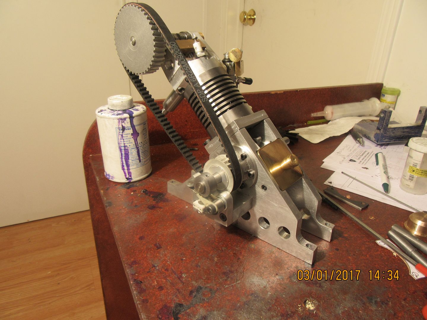

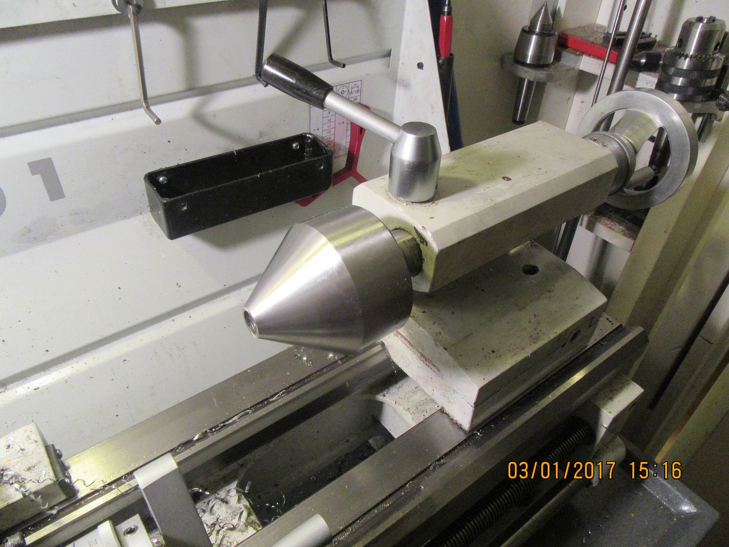
There is often more to a story than meets the eye!! Have you ever heard the phrase "a comedy of errors"? When I went to make my ill fated gas tank, all I had in my scrap bin was one ugly, nasty, short piece of galvanized pipe or tube, which was close to the right outside diameter---just enough oversize that a few passes on the outside to peel off the galvanizing, and it would be perfect for a gas tank. I know it is dramatic overkill, but I like the tubing I make my gas tanks from to have about a 3/16" wall thickness. Not because any particular strength is needed, but so I can put a nice little counterbore in the end of the pipe equal in depth to the material I am going to use for endplates. This gives me a "shelf" to set the endplate on while I solder or silver solder the endplate in place. The ugly, nasty piece of pipe I had would also require a few passes on the inside with a boring tool to clean the galvanizing of the inside as well. I set the pipe up in my lathe, and there was no way I could hold it in the 3 jaw so it would rotate smoothly without a big "wobble" on the outboard end. I tried different positions in the chuck, I tried turning it end for end, I even tried my "nudging" tool which is basically a ball bearing mounted to a piece of material that I can mount in the quickchange toolpost and push on the outboard end of the pipe until it "runs true" before tightening the chuck completely. Nothing worked, so screw it---I will machine the wobble out of it!! After taking multiple passes on the outer diameter, it ran true, but then it was quite obvious that the outer diameter was no longer concentric with the inner diameter.--At least at the outboard end---and, if I tried to bore the galvanizing out of the inside I would end up with a paper thin wall on one side of the pipe. With a ring of silver solder holding the endcap on the pipe, it would have been very obvious that something wouldn't look right.--So---Compounding "dumb" with "stupid", I decided to steel wire weld the ends in place, which would leave no tell-tale ring of solder. We all know how this worked out. The galvanizing on the inside of the pipe kept causing so many pin holes in the welds at my endcaps, that I had to reweld both ends numerous times to plug leaks. Eventually, I had poured so much heat into this poor, would be gastank, that it looked like a roasted turd at which point, I decided to throw in the towel. The upshot of this rant, is that today I bought a new piece of ungalvanized, unrusted tubing to make gas tanks from, and spent a chunk of the Rupnow fortune on a "Bullnose" center with bearings that fits into my lathes tailstock. If you don't know already, the purpose of a "bullnose" is to support the outboard end of a pipe being turned in the lathe. Hopefully, the next gas tank attempt will go a little better!!

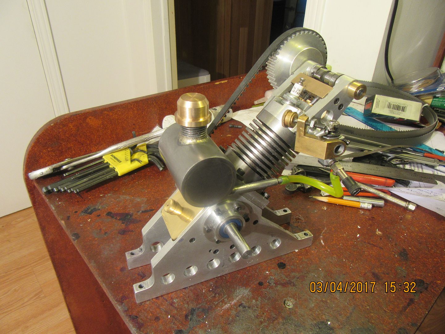
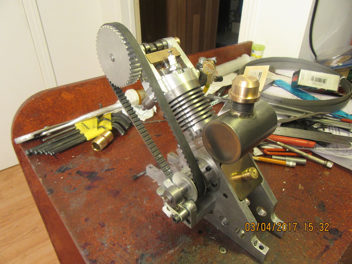
Hah!!! I knew there was a gas tank in there. All I had to do was gather up enough karma to set it free. Considerably better results this time than last time around. I am suffering from the Head cold from Hell, and should have been taking it easy today, but I couldn't rest until I had redeemed myself gas-tank wise.


$28.51
$45.00
Key Contemporary Buildings: Plans, Sections and Elevations (Key Architecture Series)
Lions Den Books321

$188.98
TM NEXDYNAMI RE41157 Water Pump Compatible With/Replacement For/John Deere 6200 7400 6300 6600 6500 6400 7220 7600 7200 RE41157
VIVID MARKET CORPORATION

$94.99
$109.99
AHS Woodmaster 4400 Maintenance Kit for Outdoor Wood Boiler Treatment
Alternative Heating & Supplies

$99.99
$109.99
AmTech300 - Boiler Treatment Professional Strength (Rust Inhibitor For Outdoor Wood Boilers)
Alternative Heating & Supplies

$45.99
Sunnytech Mini Hot Air Stirling Engine Motor Model Educational Toy Kits Electricity HA001
stirlingtechonline

$403.09
DM14 Engine Build Kit, Metal Engine Build Model Great Metal Material for Engineer for Factory
Easoger Official

$156.90 ($1.40 / oz)
Replacement Combustion Chamber Kit, Burnham V8 and V8H, 1-6 Sec, 108136-01, 1129
Lynn Manufacturing

$59.99
Sunnytech Hot Air Stirling Engine Motor Model Educational Toy Electricity Generator Colorful LED (SC001)
stirlingtechonline

$104.99
Sunnytech Hot Air Stirling Engine Motor Steam Heat Education Model Toy Kit M16-CF
stirlingtechonline

$15.99 ($0.05 / Count)
$18.99 ($0.06 / Count)
HongWay 300pcs 2 Inches Sanding Discs Pad Kit for Drill Sanding Grinder Rotary Tools with Backer Plate Shank and Soft Foam Buffering Pad, Sandpapers Includes 60-3000 Grit
HongWay US

$649.00
$699.00
FoxAlien Masuter Pro CNC Router Machine, Upgraded 3-Axis Engraving All-Metal Milling Machine for Wood Acrylic MDF Nylon Carving Cutting
FoxAlien Official

$190.00
$254.99
Genmitsu CNC 3018-PRO Router Kit GRBL Control 3 Axis Plastic Acrylic PCB PVC Wood Carving Milling Engraving Machine, XYZ Working Area 300x180x45mm
SainSmart Official

$39.99
$49.99
Sunnytech Low Temperature Stirling Engine Motor Steam Heat Education Model Toy Kit For mechanical skills (LT001)
stirlingtechonline
Mr Rupnow IS getting close. Almost all of the easy parts are made. The belt tensioner is an easy part, and I haven't made it yet. I still haven't figured out what to do for a flywheel. This has ended up being an expensive engine to build. When I include the price of the bearings, the aluminum, the pulleys and belt, the carburetor, the sparkplug, and the ignition points and condenser, we're north of $250 on this one. I might have to sell the plans for this one to recoup the cost of building it.
We've got some tension here today---But not in a bad way. This morning I finished off the belt tensioner and mounted it to the engine. I was a little bit worried about the head gasket adding to the center to center distance of the belt pulleys, but since the head gasket is only .032" thick, it didn't really have any bad effect. So, I made a head gasket and installed it just to be sure, then made up the 1/2" square steel bracket with a 3/8" stub shaft on the end of it and used a sealed ball bearing as the actual "rolling member" that contacts the back side of the timing belt. The belt doesn't really need much tension on it. Just enough to keep it from "skipping a cog" and throwing out the valve timing.
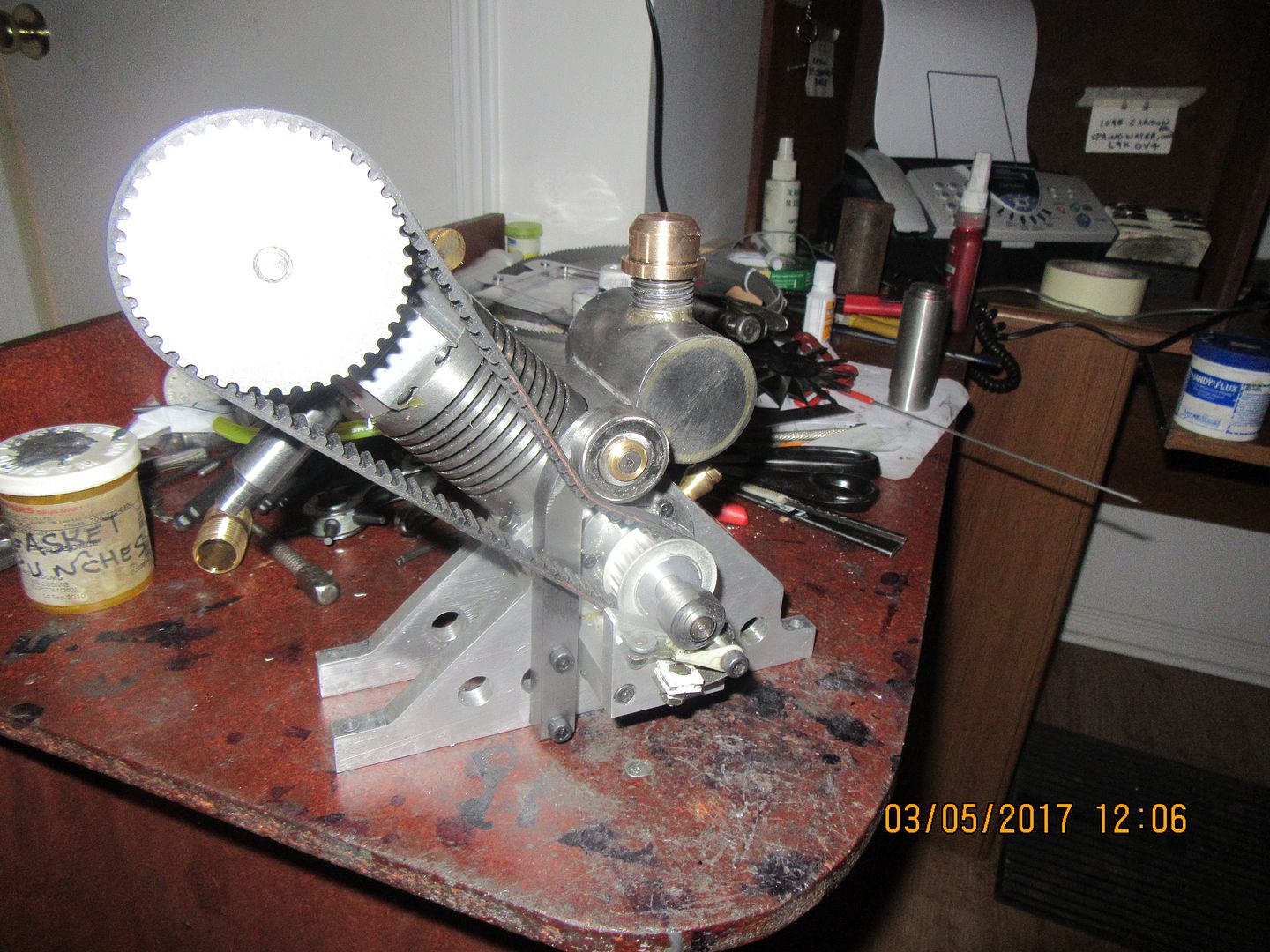
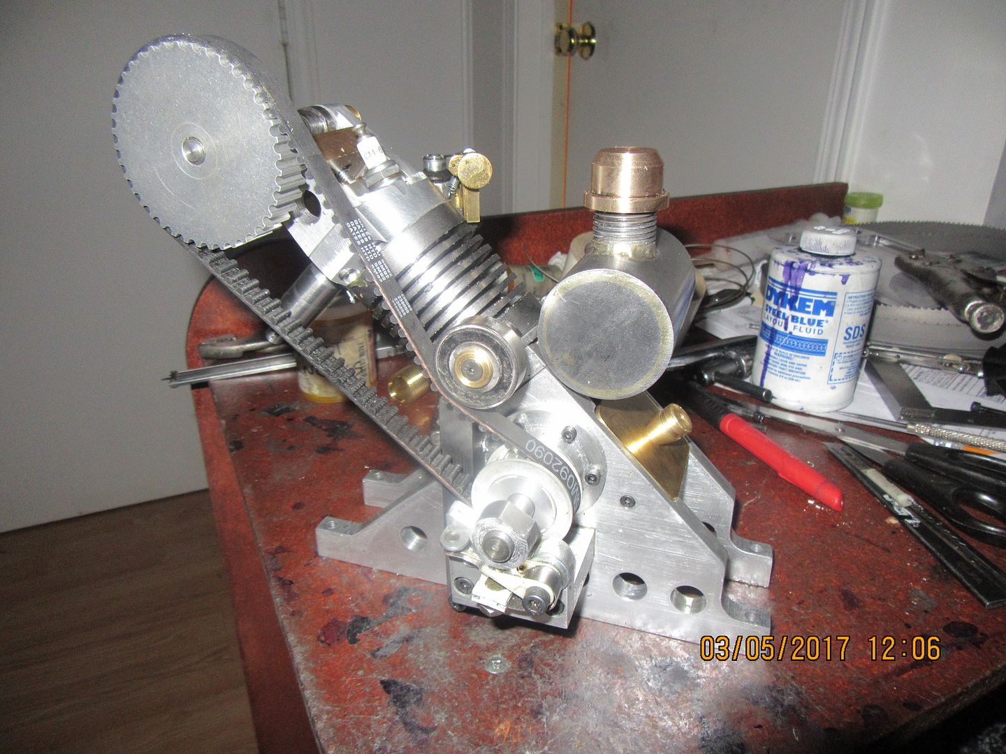


This whole flywheel thing is beginning to eat my lunch!! I could buy a piece of brass and make a pretty, functional flywheel, but I've done that half a dozen times. I could make a two part flywheel, with an aluminum inner hub and heavy wall pipe outer rim, but that too is something I've already done a number of times. Right now my mind keeps going to the fact that there has to be a zillion dead chainsaws and weed whackers out there kicking around in the small engine repair places. I may have to pursue that line of thought. My flywheel can be as large as 5 3/8" diameter. I have a mill. I have a lathe I should be able to modify almost anything to work. Thinking----thinking---
DavidLloyd2
Well-Known Member
- Joined
- Jul 16, 2016
- Messages
- 84
- Reaction score
- 111
Brian
I think it will be hard to find and fit a flywheel off a chainsaw or weed whacker. Most of them have magnets in them,
I ended up finding some 6in x 6in x1in steel from my local scrap yard and cutting it on my
band saw and finishing off in the lathe and mill,
DavidLloyd
I think it will be hard to find and fit a flywheel off a chainsaw or weed whacker. Most of them have magnets in them,
I ended up finding some 6in x 6in x1in steel from my local scrap yard and cutting it on my
band saw and finishing off in the lathe and mill,
DavidLloyd
dnalot
Project of the Month Winner !!!
Hi
Take a look at this
https://www.mcmaster.com/#casters/=16ml7z7
Find something like that used and you would be off to a good start.
Mark T
Take a look at this
https://www.mcmaster.com/#casters/=16ml7z7
Find something like that used and you would be off to a good start.
Mark T
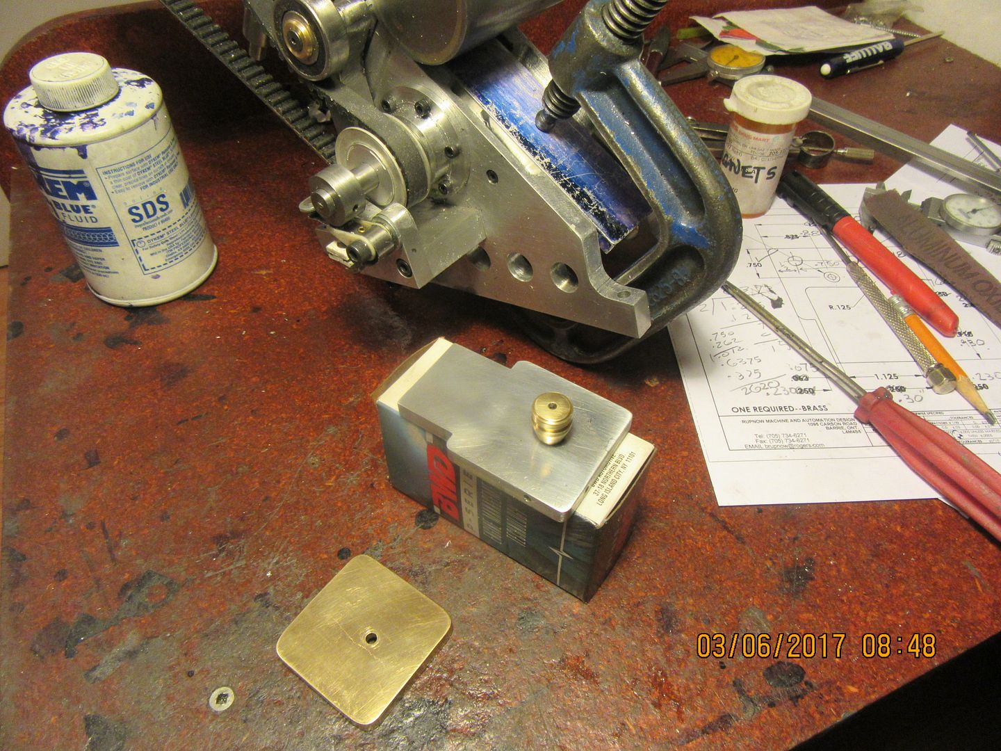
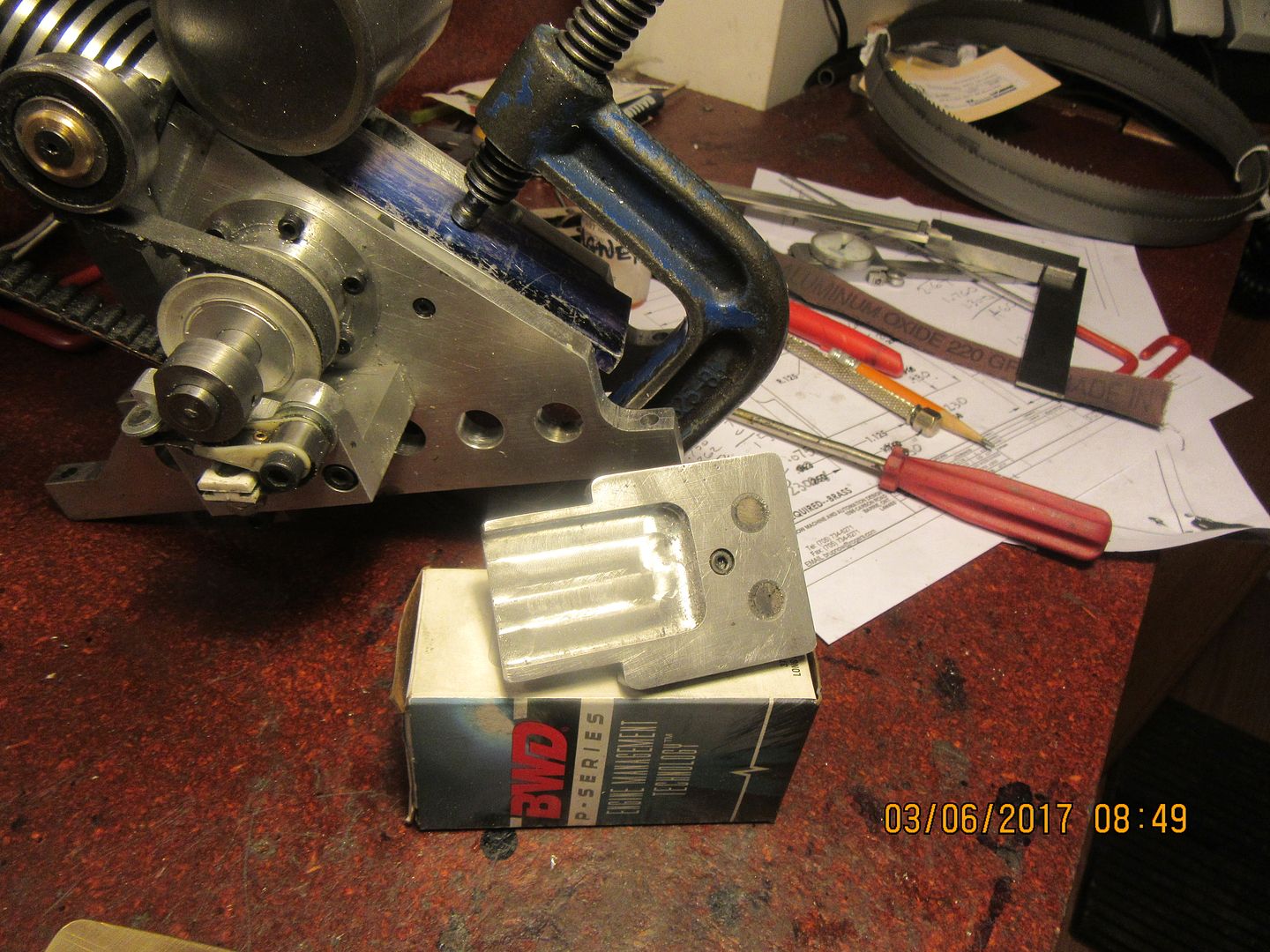
One very small last minute change to the "access hatch" that lets me oil the big end of the con rod. In my original plan, this was a small square brass plate held in place by neodymium magnets to allow fast removal to let me give a squirt of oil to the big end of the con rod. This all worked fine until I decided to make the filler plate which sets directly above the "access hatch" between the two main sideplates. I soon came to realize that there was really no good, simple way to do that because of all the other bolts buried in the sideplates which hold the cylinder mounting block in place. A few minutes head scratching, and I had it solved. ---Just make the lift off cover plate long enough to cover that area as well. I decided to forgo brass and make the new cover plate from aluminum, and it worked out really well. In the second picture you can see the reverse side of this cover plate, and see how much material was hogged out of the center to give clearance for the counterweights on the crankshaft web plates. You can also see the neodymium magnets attached in their respective counterbores with J.B. weld. The piece of heavy angle which forms the crank-case body has also been drilled and magnets J.B. welded into sockets in it as well, positioned to line up with those in the access hatch. (You can probably see the c-clamp and the scrap aluminum plate set in place to ensure that these magnets set below the surface of the pockets they are in on the engine.) I just did that this morning and it has to set up for 24 hours. With this final change, I have completed the engine except for the flywheel.


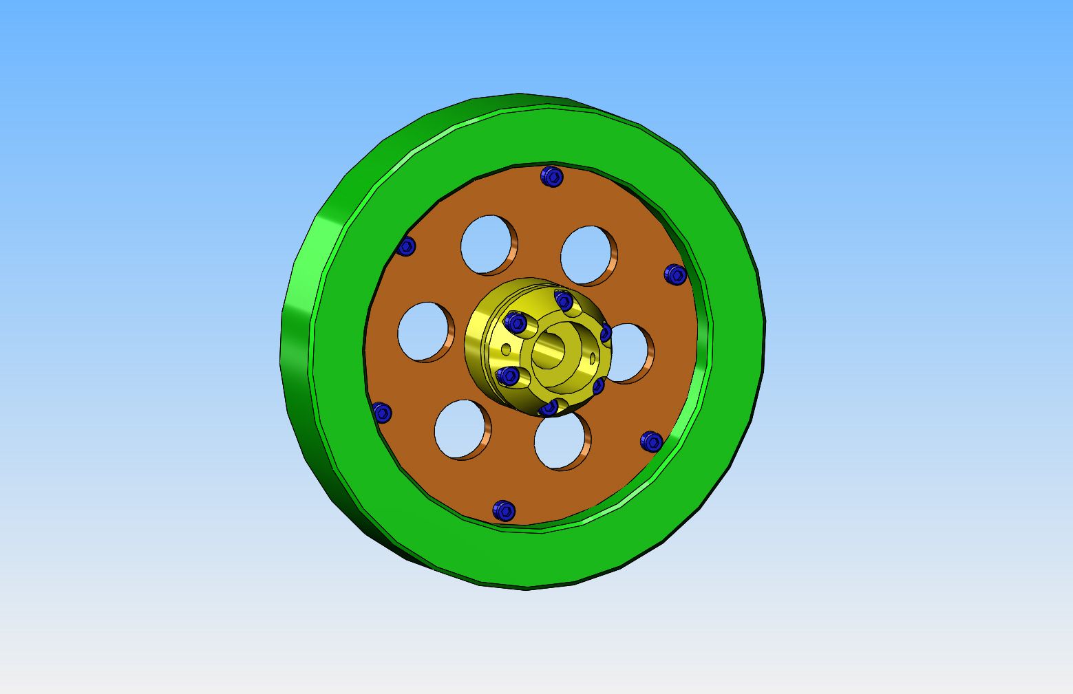
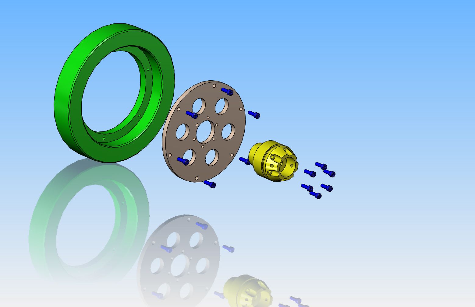
On the subject of built up flywheels--This is the way I see it today. A solid steel hub, with keyway, set screws, and built in "nose" for my starter spud. Cheap, nasty, and can be made from stub ends I have left over in my shorts bin. A web made from 3/16" aluminum plate, and an outer rim cut from a section of heavy wall tubing. Wouldn't be as pretty as bronze or brass, but would be very cost effective, and lends itself very well to painting if I choose. Maybe even paint gas tank to match flywheel.


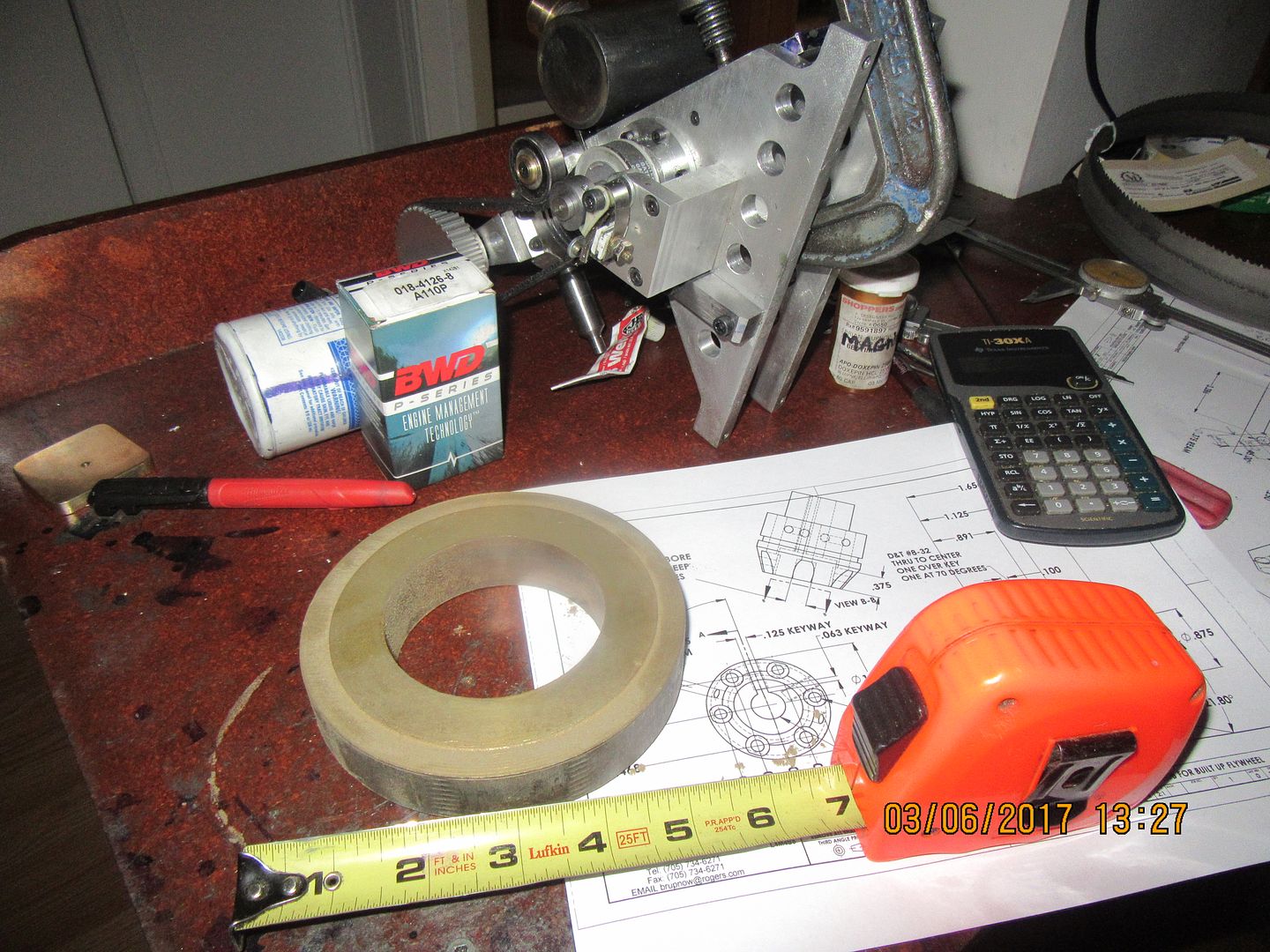
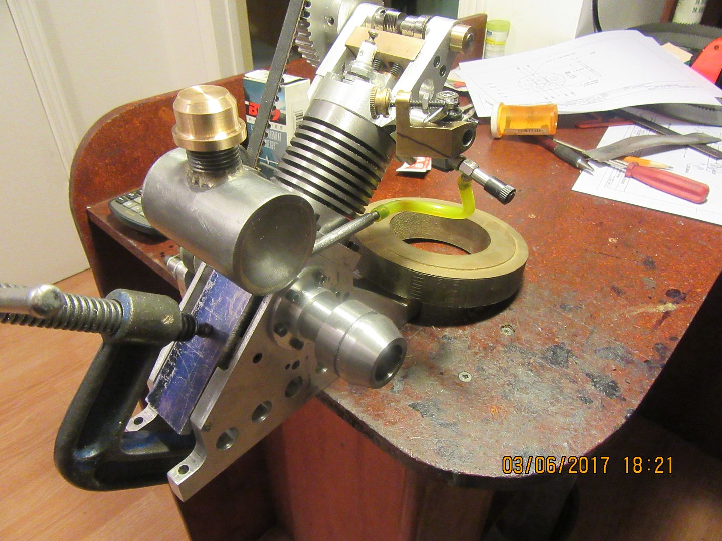
Well Sir!!---That was worth a quick trip downtown to my metal supplier/machine shop. A nice piece of 660 bronze, 5" o.d. x 3" i.d. x 1" long out of their "cut-offs" in the bronze rack for the princely sum of $10.00. I have material here for the hub and web. all I need now is the energy to make it happen.

Today got to see the built-up flywheel design finalized, and a good start made on the center hub. That center hub was an end of 1144 stress-proof left over from building a one piece crankshaft. My goodness, that is lovely material to work with!! I save all of my "chucking stubs" because they work great for little pieces like this. I'm finally beginning to recover from the "Head cold from Hell", so I'll probably be working on a design contract tomorrow "on site". If I have any energy left at the end of the day, I'll finish this part off and start on the "web" of the flywheel.

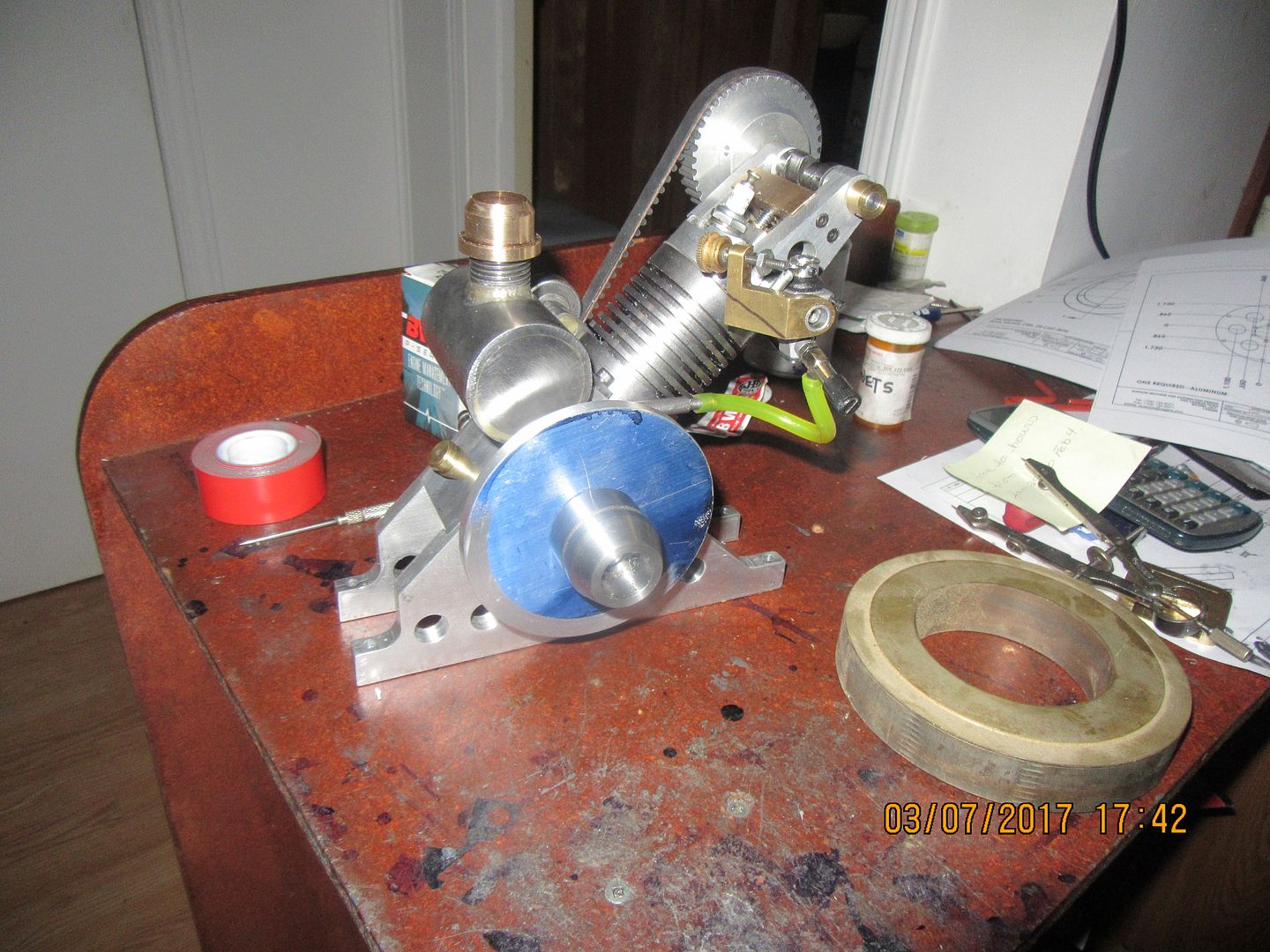
Another day--another part. Actually, I worked most of the day at a factory that makes spinforming lathes. I got home and immediately cut the 1/4" aluminum out of a piece of 1/4" aluminum angle. The material in angles isn't really flat like plate, that is why you see some evidence of turning on the face. I will "true it up" after I get farther into the flywheel build. The picture in the chuck was snapped just after I had test fitted the hub before taking the part out of the chuck. It fit without requiring further work, so I took it out of the lathe and snapped a pic of it setting on the engine.
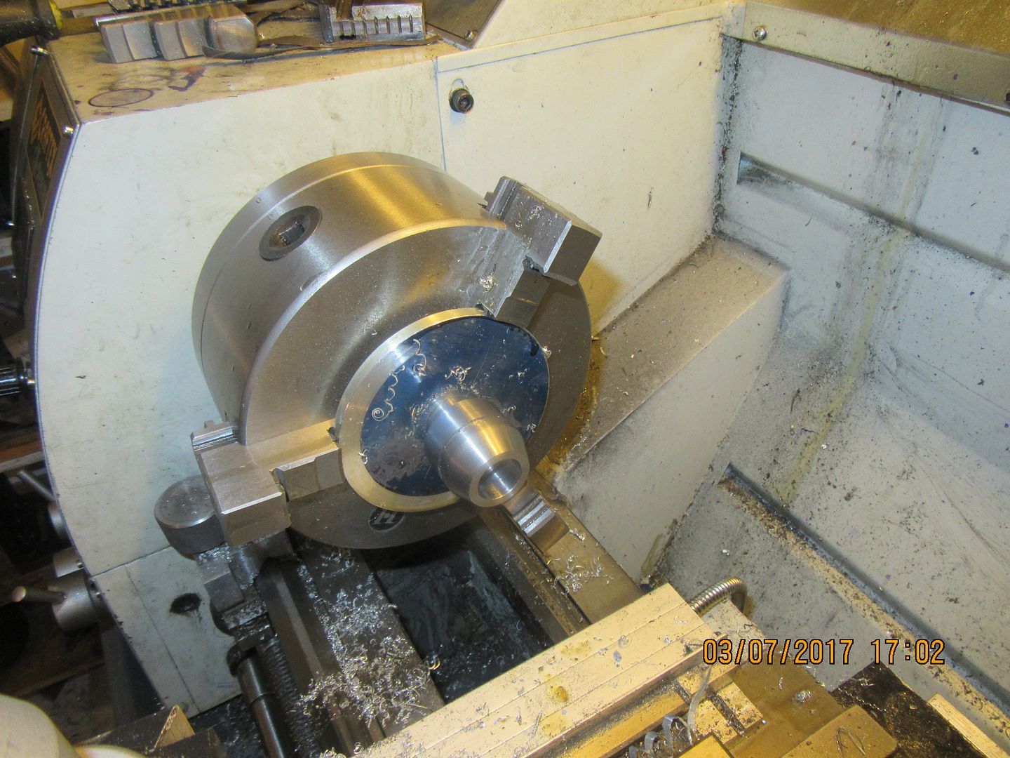


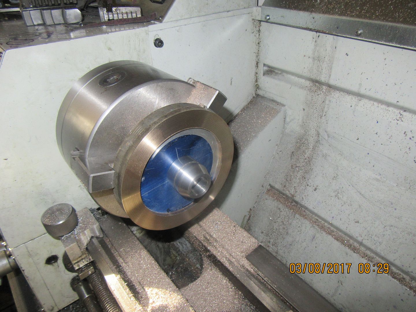
I don't have to show up at the pickle factory until 9:00 so I had time to put in the counterbore for the aluminum web and face one side of my 660 bronze ring this morning. Thru good fortune and lots of measuring I have managed to keep all of my concentric fits nice and tight, so I don't expect much runout on this flywheel when it is all assembled. Tonight I will flip the ring around, hold the bored inner diameter with expanding chuck jaws, and finish machine the outside diameter and clean up the other face.

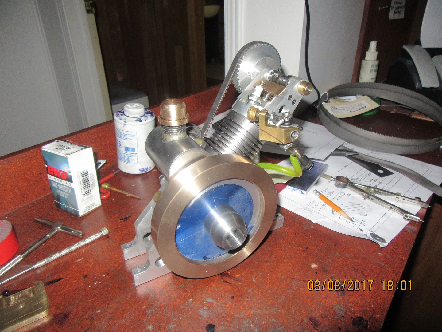
OH YEAH!!! Nothing says it quite like bronze!!! I really like this, and as I had hoped, it fills out the engine so it doesn't look skinny anymore. Now I have lots and lots of holes to tap and some "lightening" holes to drill in that web. The "lightening holes" don't really do anything. It's just that without them a video doesn't show the engine running all that clearly. There is about 1/8" of clearance between the side of the flywheel and the gastank. You will notice a little bit of brass "jewellry" on the carburetor. Those Traxxas carburetors don't have any spring to hold the throttle in any particular position, so if you start the engine it immediately tries to run at wide open throttle. I have added a small return spring and idle adjustment to this one.

Similar threads
- Replies
- 7
- Views
- 4K
- Replies
- 57
- Views
- 12K
- Replies
- 30
- Views
- 8K


