Rupnow Ovehead Cam Air Cooled

Home Model Engine Machinist Forum

Help Support Home Model Engine Machinist Forum:

This site may earn a commission from merchant affiliate links, including eBay, Amazon, and others.
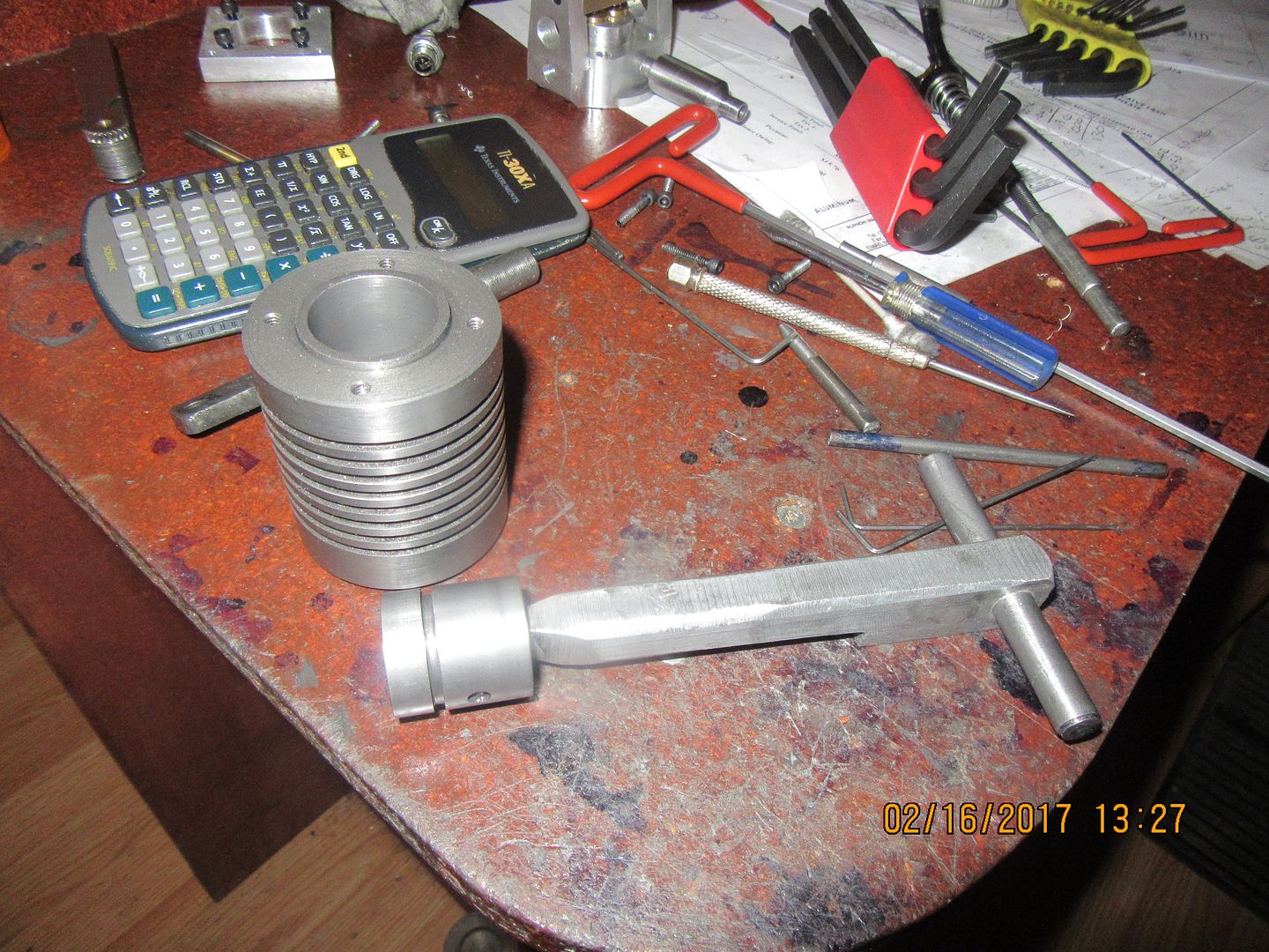
This morning I have a piston on the go. It is going to be made from cast iron. Why?---Because when I buy cast iron to make cylinders from, I always buy a piece about 3" longer than I really need, so I have something to hang onto with the lathe chuck while the cylinder is being machined. All these left over bits from making cylinders eventually get recycled into pistons. I could have use aluminum and it would have worked just as well, but I didn't have any aluminum the right size. The outside diameter is turned to be 0.003" larger than the bore of the cylinder. That over-size will get addressed a bit later. I have put the round counterbore into the "open" end of the piston, and cut the ring groove with my .094" wide parting off tool. My next step will be to hone the inner bore of the cylinder with my 3 stone brake cylinder hone to knock down any high spots inside the bore (which was put in with a 1" reamer). Then I will "dress" the piston with 280 grit carborundum paper strips while it is still set up in the lathe until it just starts to act like it might fit into the end of the cylinder, but doesn't slide freely in. At that point I will remove the piston from the lathe and set it up in the chuck on my rotary table to complete the machining operations.
 
Remember how I said that you just want the piston to start into the cylinder, but not slide all the way in. All of the other machining operations are then finished on the piston, and my "special tool" which has a wrist pin sized cross hole in the end is slid into the piston, a dummy wrist pin is pushed into place and locked there with the wrist pin retaining screws. The piston is then coated with green diamond lapping compound, and then the piston is "wrung" into the cylinder in a sliding, twisting motion. I always find that this part is much harder and takes longer than I think it will. After an hour of pushing and twisting, and occasionally having to run out to the arbor press to get the piston "unstuck", the piston will go all of the way thru the cylinder, and is virtually an air tight seal. It would probably run this way with no ring on the piston at all. I will now wash the inside of the cylinder and the outside of the piston with laquer thinners and an old toothbrush to remove any remaining diamond compound, and move on to machining a connecting rod.
 
I had almost finished this connecting rod yesterday, but after almost 12 hours in the shop I was quite happy to quit for the day when my wife got home at 7:45 from her job. Today I did the final clean-up and fettling on it and it is finished. The picture shows it setting with two tiny sealed ball bearings in the wrist pin end, and an oilite bronze bushing in the crankshaft end. My hands are sore today from wringing the piston into the cylinder yesterday.
 
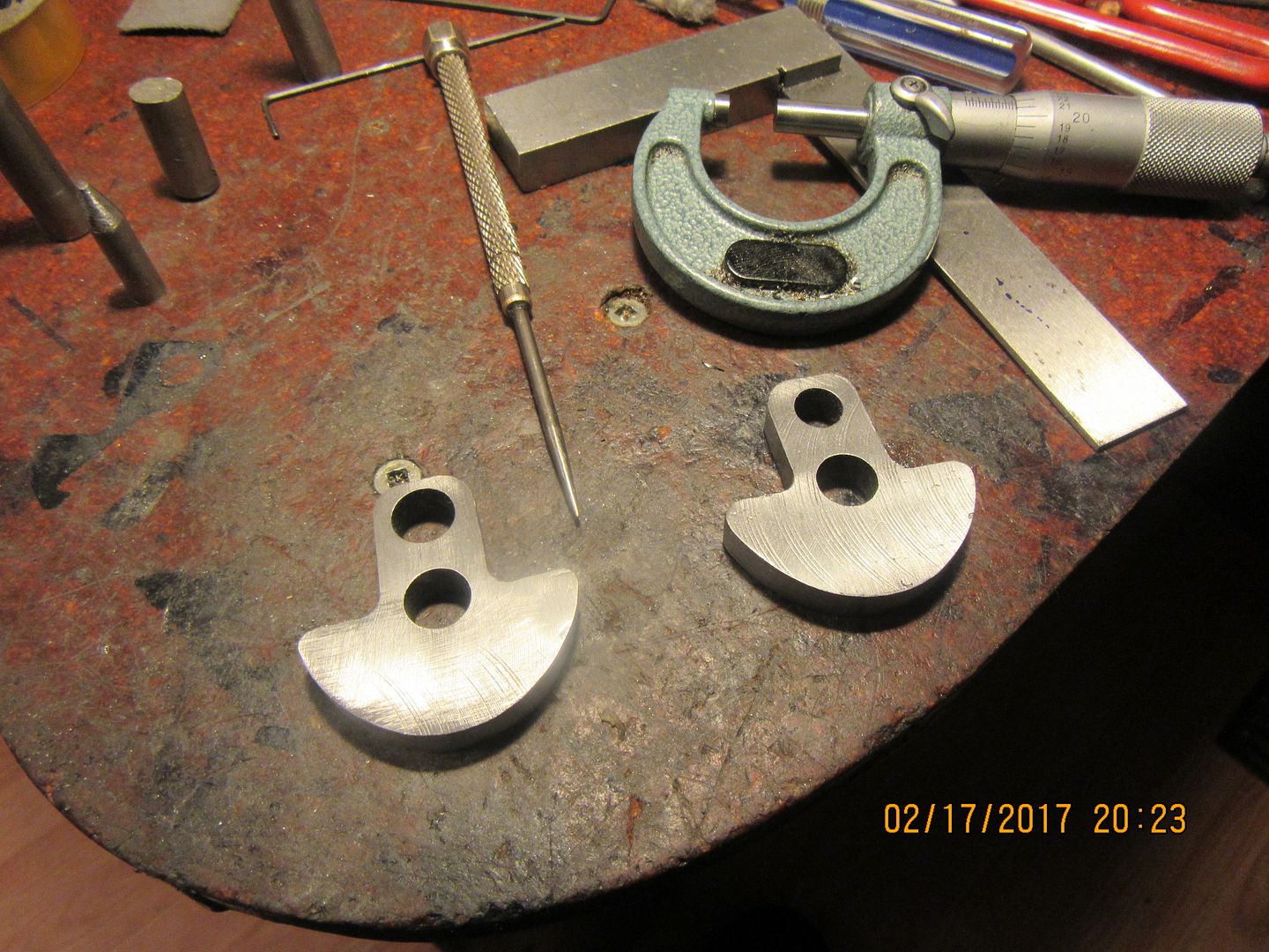
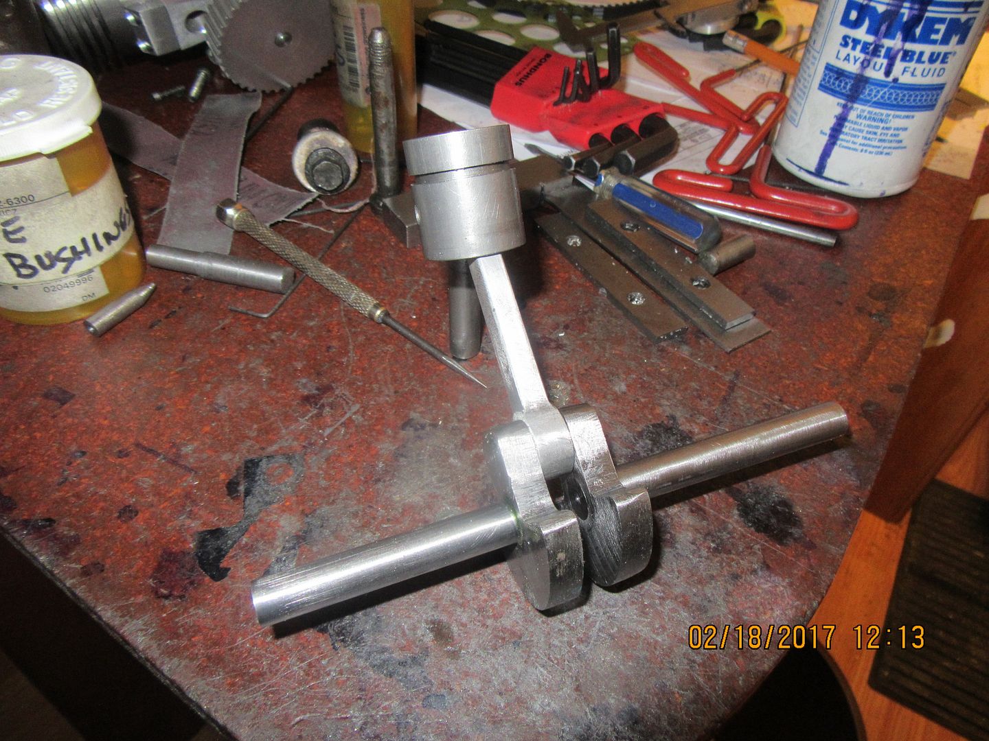
Today I made crankshaft webs. I didn't originally plan on having counterweighted webs, but the weight of that cast iron piston really surprised me. I have been making pistons from aluminum for so long that I forgot how heavy a cast iron piston could be. I decided that this engine would need counterweights to offset the weight of the piston. The webs are made from 5/16" 1018 flat bar. I didn't realize it when I designed this engine, but 5/16" flatbar is not something commonly stocked by Barrie Welding where I buy most of my material. I ended up getting 3/8" flatbar and flycutting 1/32" from both sides to keep it from warping. Three of the holes are reamed to 0.3735", and one is drilled to 5/16". I will make the crankshaft from 01 drill rod, not because it has to be hardened, but because drill rod comes in at on size to .0005" over, while cold rolled 1018 comes in .0005" undersize. When you are pressing crankshafts together instead of machining from solid, that .001" difference between drill rod and plain cold rolled rod makes a big difference on how well the crankshaft stays together. The rod journal will be machined from 3/8" drill rod, and pressed into the driver side web. The main body of the journal that the rod sets on will be turned to 0.3125". This is going to be a two piece crankshaft, with a driver side and a driven side. The end of the rod journal that fits into the 5/16" drilled hole in the driven side web is a clearance fit.
 
Houston, we have a ---crankshaft!!! One thing to be aware of when using drill rod for crankshafts. Since it is .0005" oversize, it won't fit thru the 3/8" ball bearings. The trick here is to determine exactly how much of the shaft must go thru the bearings (in my case, all of the shaft that isn't pressed into the webs), put it in the lathe, and work it down over its full length with 220 grit carborundum cloth strips. This is not hard to do, it's just time intensive and requires a lot of "Stop the lathe and try the bearing to see if it fits onto the shaft yet". The end of the shaft which is getting pressed into a 5/16" web plate is left 15/16" long, and not touched with the carborundum cloth. Turn down 5/16" of length at the end to .372". Then turn the next 5/16" down to 0.374". Use a thin strip of carborundum cloth to smooth the shoulder which results being 3 different diameters. Clean the parts which get pressed together with laquer thinners and a Q tip. The press fit is going to be more than a 2 ton arbor press is going to be able to handle. This pressing gets done in my big shop vice. You need a hollow socket or something to accommodate the part of the shaft which has been turned undersize because it is going to "stick thru" about 5/8" on the wrong side of the web when the pressing is completed. coat all the areas of the shaft which are going to be pressed with 620 Loctite, and have at it. After the shaft has moved about half way home, loosen of the vice in case things are going a bit crooked, then take it the rest of the way home. this is a very hard press fit. Trim the "stick thru" part with hacksaw or in the lathe, and you're done.
 
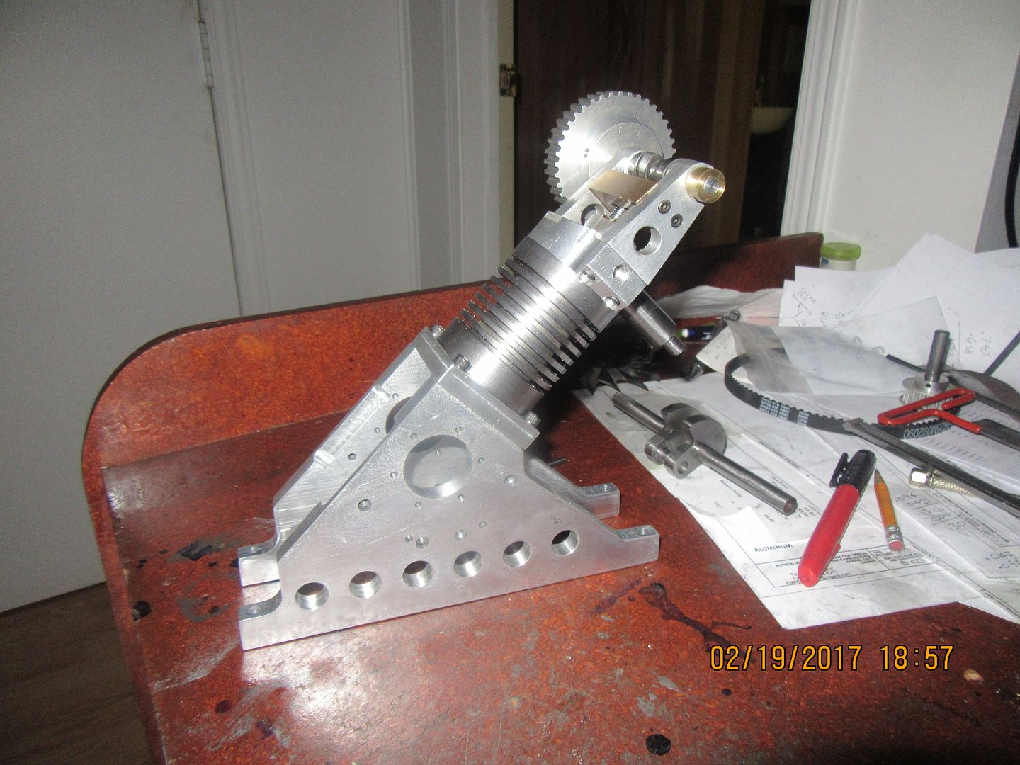
There is an undefined point when a craft begins to become art. These sidepates are getting pretty close to that point. I like them a lot. I know that there is two full days of work in getting them to this stage. The engine will look a lot more balanced once the gas tank is completed and fitted to it.----Brian
 
This morning I finished the angle that fits between the two sideplates and forms the central body of the "crank-case". Everything went together okay, but something didn't look quite right. Finally, I realized that I had misread my own drawing of the sideplates and put the recess for the 1/4" brass inspection door about 0.4" farther down from the peak that I had intended. Oh well, no harm, no foul. I can still get at the big end of the con-rod to give it a squirt of oil, and that's really all I wanted to be able to do.
 
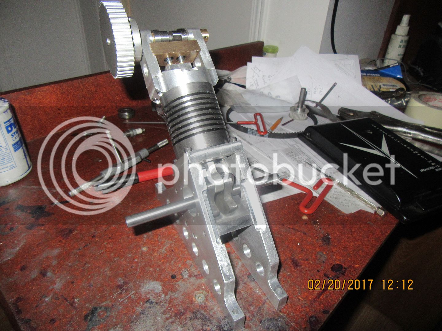
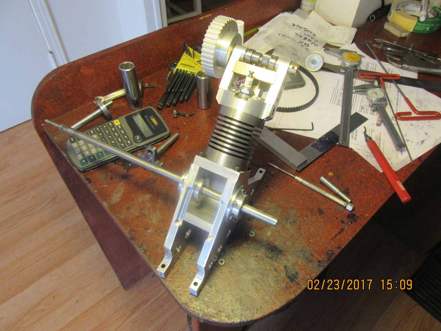
Both bearing housings are machined and bolted up to the sideplates, and the sealed ball bearings and spacers are installed with a little skim of Loctite and an alignment rod. I like to give .001" to .002" clearance on the bearing housing bores. That lets the bearings align themselves when everything is assembled, and the alignment rod ensures that the bearings will all be lined up after the Loctite sets up. The bearing housings actually extend into the "crankcase" area, and will serve to locate the crankshaft side to side when it gets installed. at least, they would in a perfect world. I always seem to end up having to make an additional spacer/washer, or else skim a little material off to get things perfect.
 
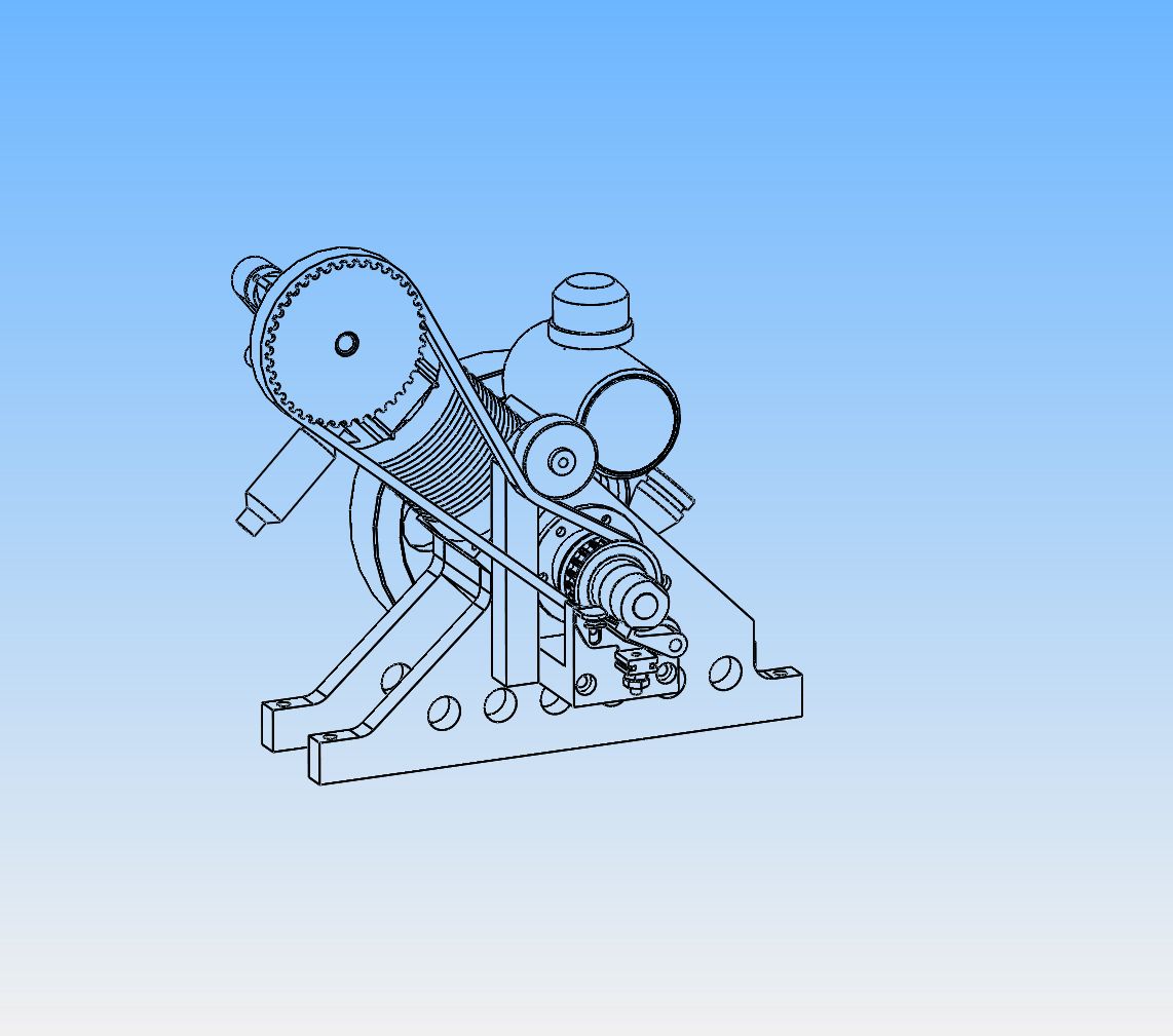
There isn't any particularly graceful way to mount a belt tensioning pulley on this engine, so it will be a simple ball bearing mounted on a 1/2" square piece of stock. The piece of stock will bolt to the engine sideplate.
 
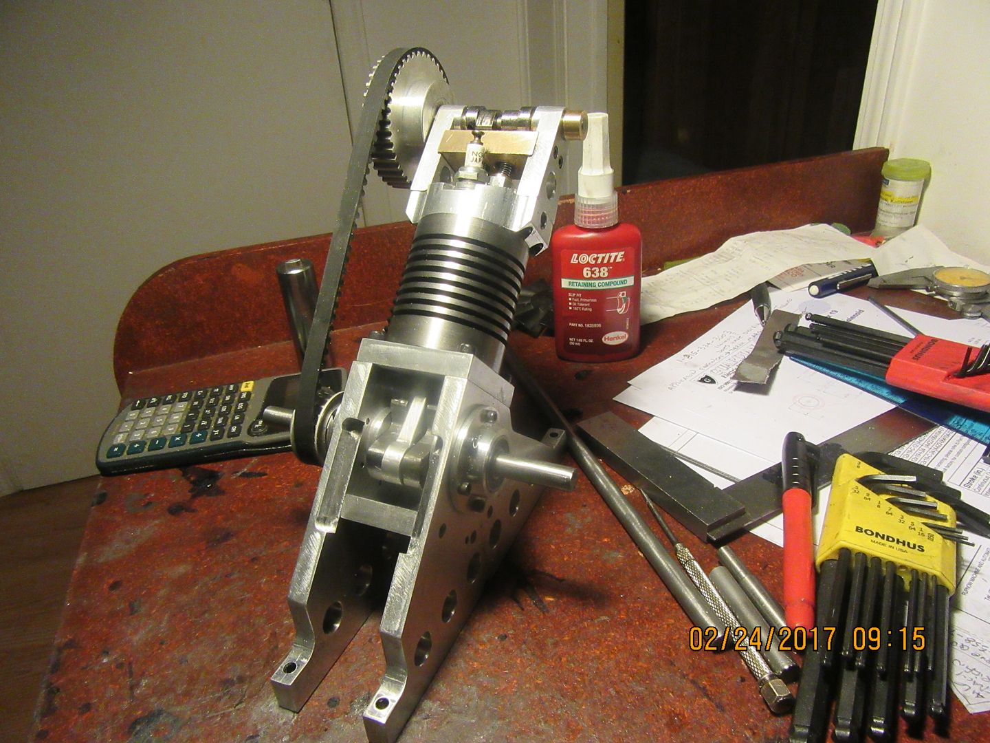
So far, the news is good. With everything reassembled, the crankshaft rotates feely, the piston goes thru it's full travel, and the con rod doesn't hang up on the bottom of the cylinder. The timing belt I ordered seems to be the correct length. Other than a mount for ignition points, a flywheel, a belt tensioner and some assorted inspection plates the engine is almost finished.
 
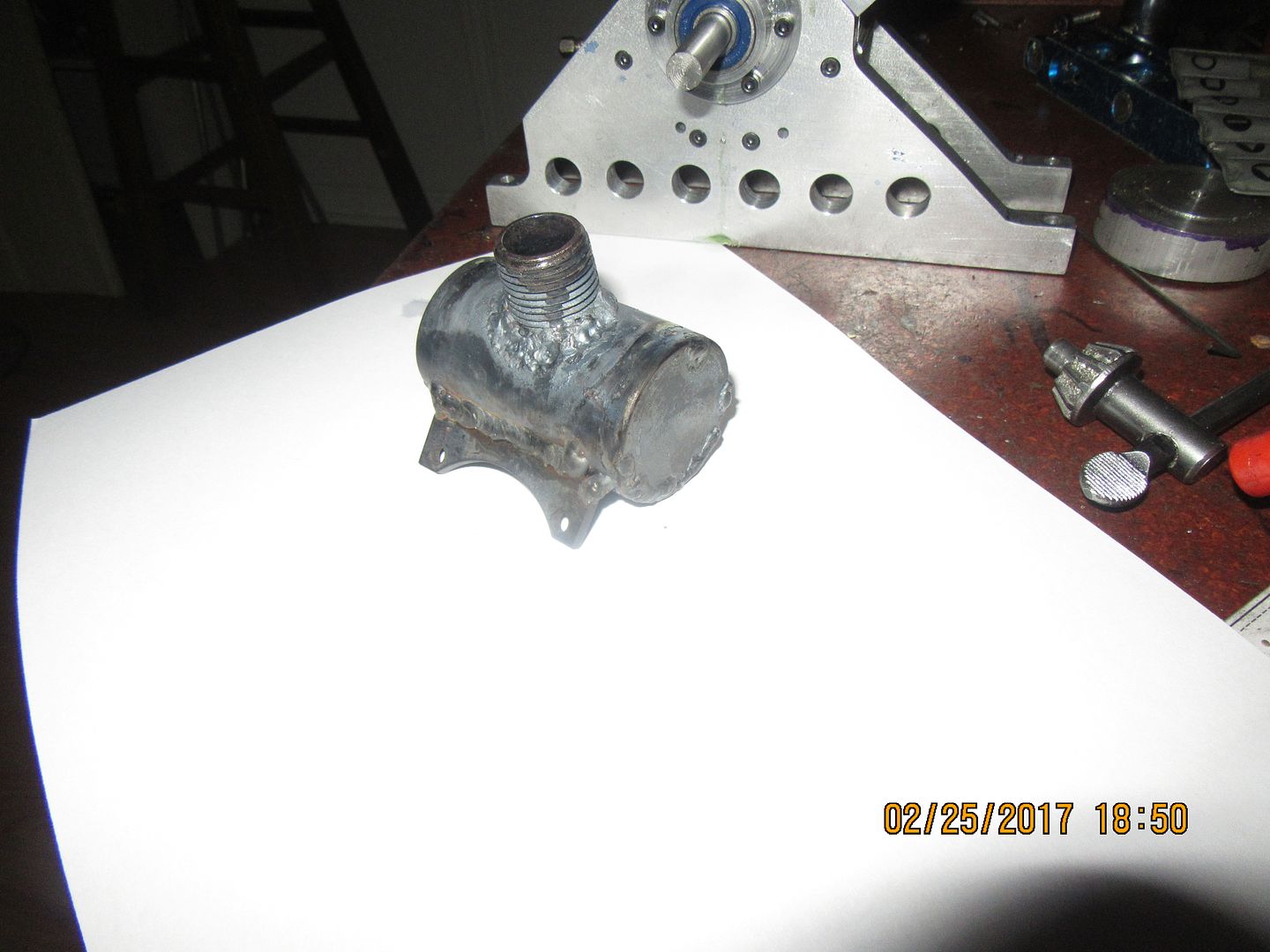
Today I've made the gas tank, and I'm doing something that I haven't done for many, many years. In the pre mig days, I was an avid hotrodder, who patched up many rusted out antique car bodies. At first I used oxy acetylene torches and brazing rod, which gave fast and fairly easy results. Then, as I got into it deeper and deeper, I came to realize that the proper way to fix car bodies wasn't to braze patches over rusted metal, but was to cut the rusted metal out completely and replace it with new metal, not lap welded but butt welded with oxy acetylene and steel filler wire. I became an excellent welder using only steel welding rod, and fusion welding body metal with no filler rod at all, just melting the old metal and new metal enough to let them flow together and immediately fuse without filler rod. This is something that takes years of practice, and I became very good at it. Practice DOES make perfect!!! So---Today I welded the end caps and filler neck to the steel pipe which forms the body of the gas tank for this engine using oxy acetylene and steel filler rod. Why?--Just to see if I still could, and to avoid having a ring of braze or silver solder showing at the ends of the tank. I'm not sure yet how well this is going to work. If I end up with leaks that I can't weld shut, then I'll have to start over again on the tank.
 
Well, that was ahhhh---interesting. I can still steel wire weld with oxy acetylene. I have a few minor leaks at one end. (the tank is full of water in the picture.) One thing about welding with steel wire--if you have a leak, you can go back and reweld the leak area without melting anything else out. Poor little tank looks a bit like a roasted turd!! I can do a lot of sanding and clean-up to improve the looks, but I have some heat related pitting around the filler neck that isn't going to sand out. I'll think about this overnight. If it doesn't clean up respectably, I may use a bit of bondo on the pits and paint the tank. It was fun to weld it this way, but my eyes at 70 don't enjoy looking into the melt puddle nearly as much as they did at 40.
 
I've been chasing leaks all morning. I'm about at the point where I may take Sid's advice and try a different method. This is one of those situations where I had to "Try it and see if it worked". I'm not out any money. All the parts are scrap I had laying around. The tank body was a horrible old piece of galvanized pipe that I dug out of my scrap steel bin. If I don't achieve a leak proof tank in the next 20 minutes or so, I will buy a new piece of black steel pipe at the hardware store and silver solder the end caps and filler neck in place.
 
Nice, what did you use for welding wire, a coat hanger?

I would recommend using a 4 percent silver content soft solder. Easy to do and works at low temperature so no problem with burning the base metal or warpage.

Mark T
 
I used 0.060" diameter copper coated steel welding rod. The same stuff I welded 100 old car bodies together with in the 1980's. Give me a little credit here. We don't do coat hanger wire.
 
At this point, I'm going to declare a complete and utter "FAIL" on the gas tank. The welds were fine, albeit somewhat lumpier than they were when I was doing that a lot in the 1980's. I just couldn't get ahead of the pinhole leaks. Nothing ventured, nothing gained. I did save the fancy little plate bracket that holds the tank to the engine. Later this week, I will try again with a new piece of black steel pipe from the hardware store, and brass endplates silver soldered into place. As I said before, I don't do well with soft solder.
 
Hi

I used 0.060" diameter copper coated steel welding rod. The same stuff I welded 100 old car bodies together with in the 1980's. Give me a little credit here. We don't do coat hanger wire.

Sorry Brian. We don't get a chance to pull your chain very often so I couldn't resist.

Mark T
 

Latest posts

Back
Top