Rupnow Ovehead Cam Air Cooled

Home Model Engine Machinist Forum

Help Support Home Model Engine Machinist Forum:

This site may earn a commission from merchant affiliate links, including eBay, Amazon, and others.
Sorry brian but when i read the first sentence I had to laugh.

Suggestion 1 - Mount your readout on the wall left enough of the chuck so coolant wont splash on it and swarf wont get flung on it. This way you can switch your eyes back and fourth between the chuck and display without even moving your head. It's a bit more comfortable than having to turn your head to the left all the time.

Suggestion 2 - When you power feed watch the DRO on the first pass to get the shoulder located. Then power feed watching the part and run right up just short of the shoulder and undo the power feed lever. Then look at the DRO and finish up the last bit. With a little practice you will be able to stop .010 short of the shoulder and then just bump in by hand. This way you are never power feeding without looking at the actual tool bit.

Once you get used to it, you will never want to be without the darn thing.
 
It's okay Steve---I've been laughed at for far lesser things. I like the DRO. It's just a "new thing" that I haven't done before.---Brian
 
Hi Brian
Neat engine design, looking forward to the build. With the DRO it might be worth investing in one of those soft plastic covers for the readout, keep the oil and crud off and when you can't see through it just replace it
Cheers John
 
John--that display comes with a clear plastic adhesive sheet on the front of it that can be pulled off and replaced when it gets too dirty.---Brian
 
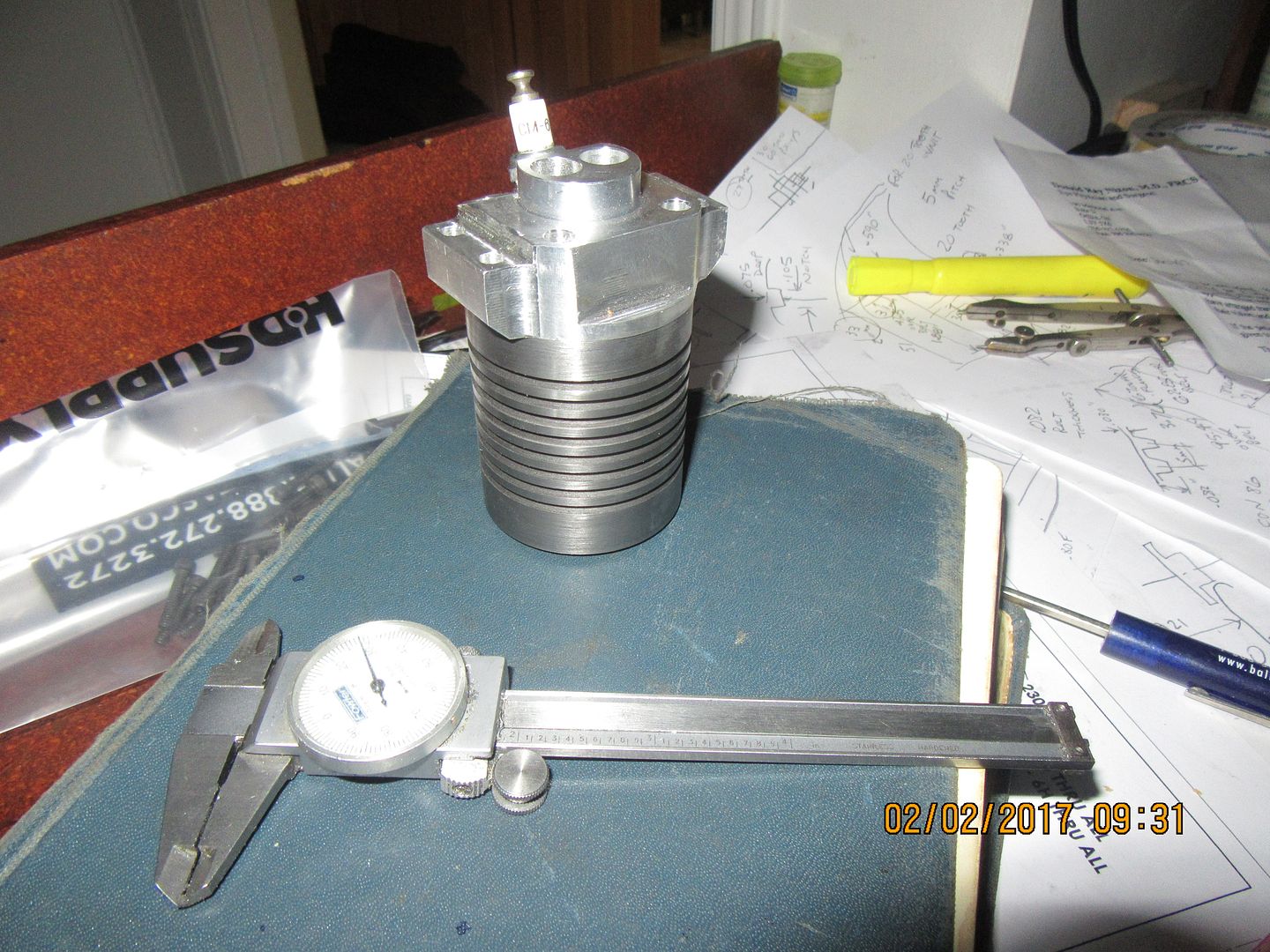
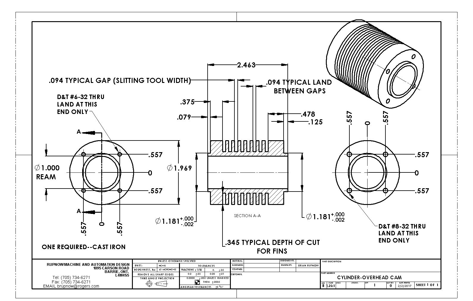
This morning we have a cylinder. The fins are all the same width, and trust me, ---that's a good thing!!! I have a tailstock live center that is just barely large enough to act as a bull nose to prevent the outboard end of the cylinder from moving under the side pressure of cutting the fins. I always drill the center bore out before cutting fins. Start with a 3/8" drill and move up by 1/16" increments until I get to 15/16", then drill thru with a 31/32" drill, then ream to 1" finished bore. I cut the grooves between fins .094" wide x 0.345" deep using a 3/32" HSS parting off blade and the lands between grooves are .094" wide. The lathe was turning at 230 rpm. and I cut the fins almost full depth with automatic feed, except for the last .025" which I fed by hand, so as not to overshoot. Although it made a Hell of a racket it got the job done right smartly.
 
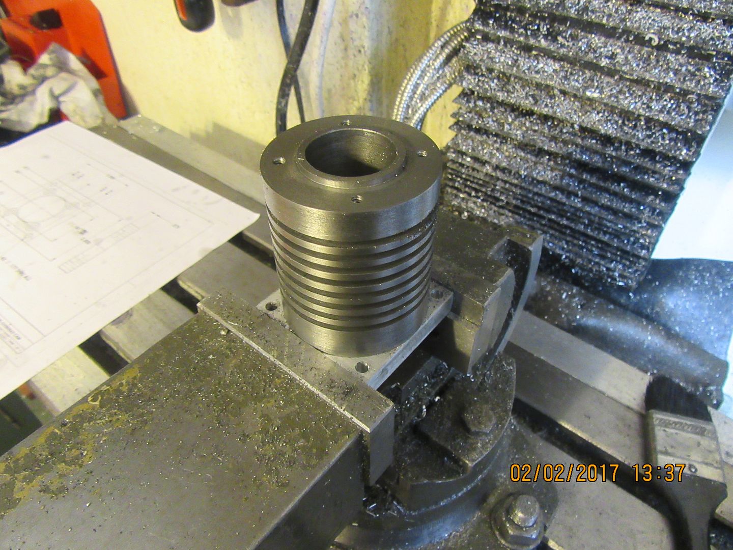
I have a question, and it's a hard one. Fortunately, I also have the answer to the question. On a cylinder like the one in the drawing, after you have tapped the four holes in one end, how the heck do you turn it around and put the tapped holes in the other end in the same rotational orientation? This is almost impossible to do.-------Unless-----You have a rectangular plate that bolts onto the other end. If you do, you make the rectangular plate, bolt it onto the first set of holes in the cylinder, then hold the plate in the vice so you can tap the holes in the other end of the cylinder, with assurance that the second set of holes really will be aligned rotationally with the first set of holes!!

 
News is not good. The company in North Carolina that sold me timing belts and pulleys 5 years ago mailed them to me. Now they say they can no longer mail things to Canada, and that they want a $50 courier fee for $25 worth of parts.---plus tax---plus customs fee---plus difference in Canadian and USA dollars. I was ready to eat the difference in Canadian/American dollars, but this is a bit too much like robbery for my taste. I'm now trying to source the pulleys and belt from a Canadian supplier.
 
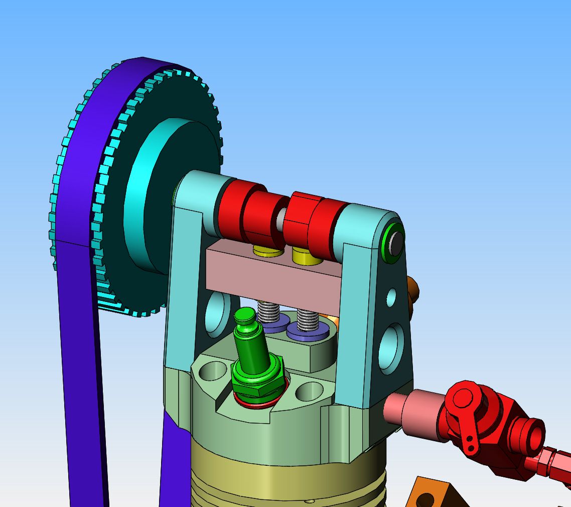
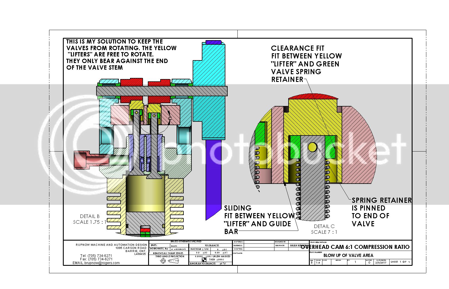
I think I'm going to have to do something to keep those yellow "lifters" from rotating. Ordinarily, you would want them to rotate a bit each time the cam lobe "wiped' across the top of them to equalize any long term wear pattern. In this case however, if they rotated it would make the valve rotate----and we don't want that. Valves like to settle into one spot and stay there, and that is where they will "wear in" a seating position and seal tighter than a ducks butt. If they rotate a bit with every "wipe" of the cam lobe, then they are going to not seal consistently and will probably quickly wear away the valve seat area on the valve cage.
 
After an extensive internet search, I find that there is a lot of contradictory information as to whether or not valves should or shouldn't rotate in an internal combustion engine. Some say no, they shouldn't rotate at all. Some say, yes, they should be forced to rotate fractionally with every cycle to even out wear on the seat. Some say they should not be restrained and allowed to rotate if they "want to". I am in agreement with the "not rotate at all" crowd. I have revamped my design a little bit up at the top of the valves, primarily to keep the yellow "lifters" from exerting any "torque" to the valves through tight clearances. They will still contact the very end of the valve stem, and it's possible that they might try and impart some turning force on the stem thru that end contact, but I'm willing to take a chance and find out. There is a world of design in that tiny area at the top of the valves.
 
I have never given this business of rotating valves a lot of thought. There is really nothing on my engines that encourages the valves to rotate.---Then again, there is nothing to stop them from rotating. True, we lap the valves into the seats by rotating them with some compound. However, once the engine starts to run, it actually does "pound the valves down into the seats" every time the cylinder fires. That is why valves seal so much better after the engine has been running for the first 5 or 10 minutes. I do agree that a slight angle or crown on the end of the valve stem will help to prevent any torque from the end of the lifter being transferred to the valve stem.---Brian
 
After much phoning around and hair pulling, I found a company in USA that would mail parts to Canada rather than ship via courier. This is much more economical, but there is a catch. Their pulleys and belts at $46 American look the same as the other companies parts which were $17 American. So, being grateful that God made me rich instead of good looking, I ordered them anyways.
http://sdp-si.com/
 
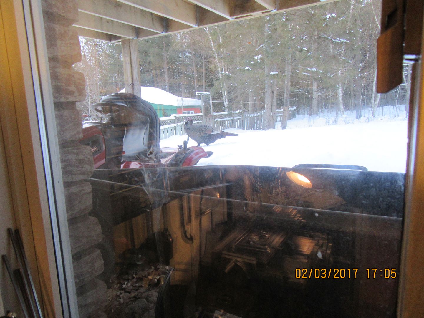
I had some visitors drop by this afternoon while I was running my milling machine. My machine shop window looks out into our back yard, and these guys all marched right by about 2 foot outside the window. There were 18 wild turkeys, who troop over to my backyard once a day to check out what has fallen from my bird feeder. Of course, by the time I shut down the mill and hunted up my camera, the parade past my window was finished, but I did get one close up, and some of the rest as they were marching back into the woods. What a treat!! My goodness, they are big birds!!

 
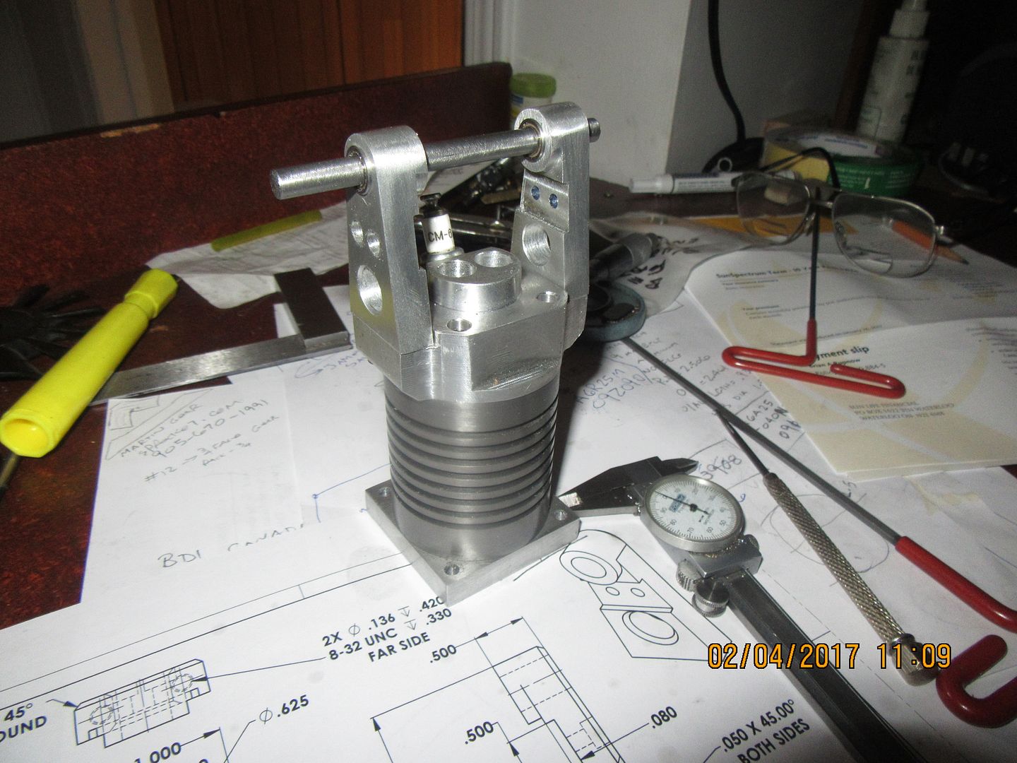
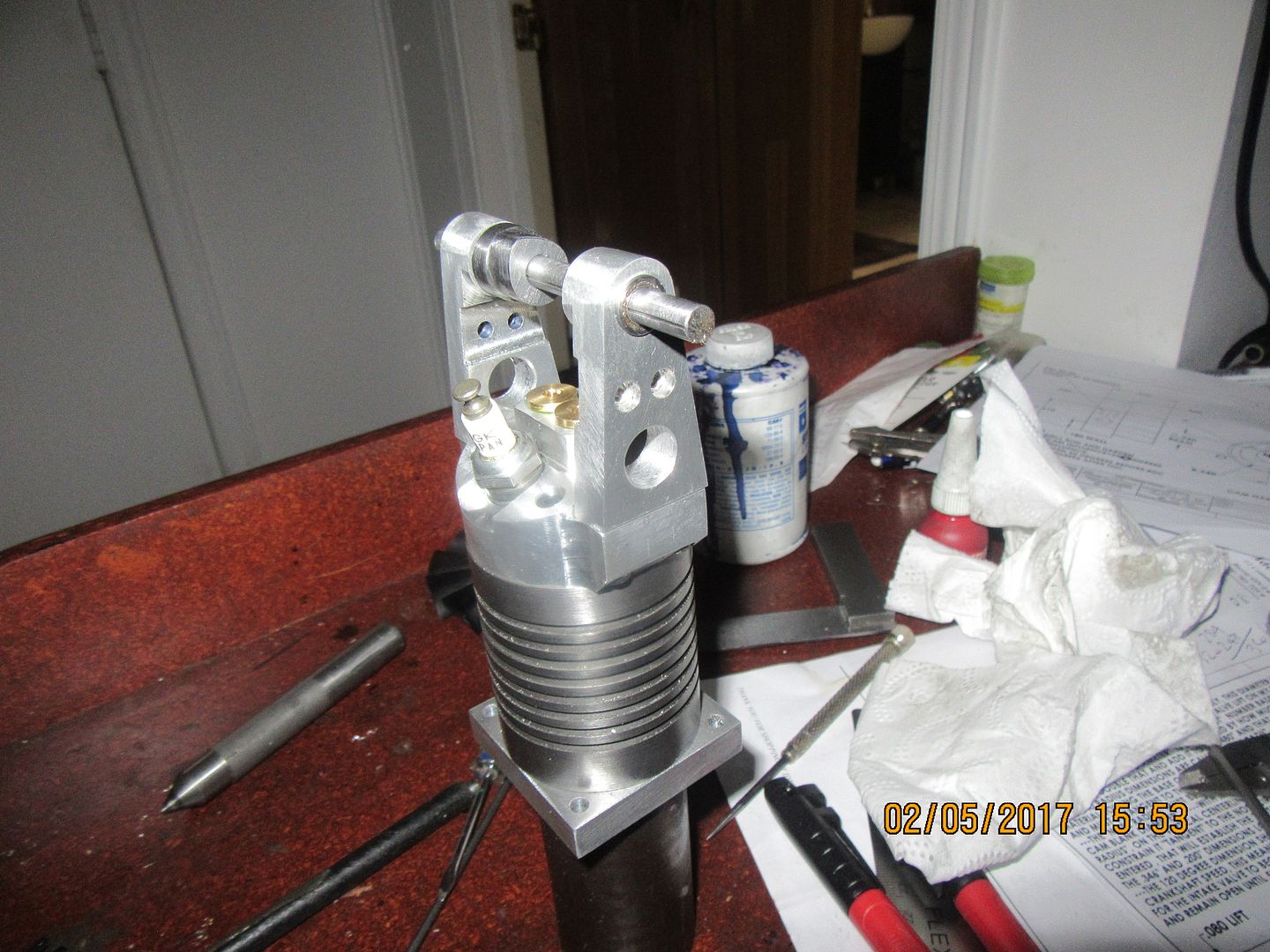
And here we have the great horned beast of legend---Well, not really, but those cylinder towers certainly give things a different flavour!! The flanged ball bearings are a nice snug fit into 3/8" reamed holes in the towers, and have a 1/4" I.D. for the cam shaft to ride in.
 
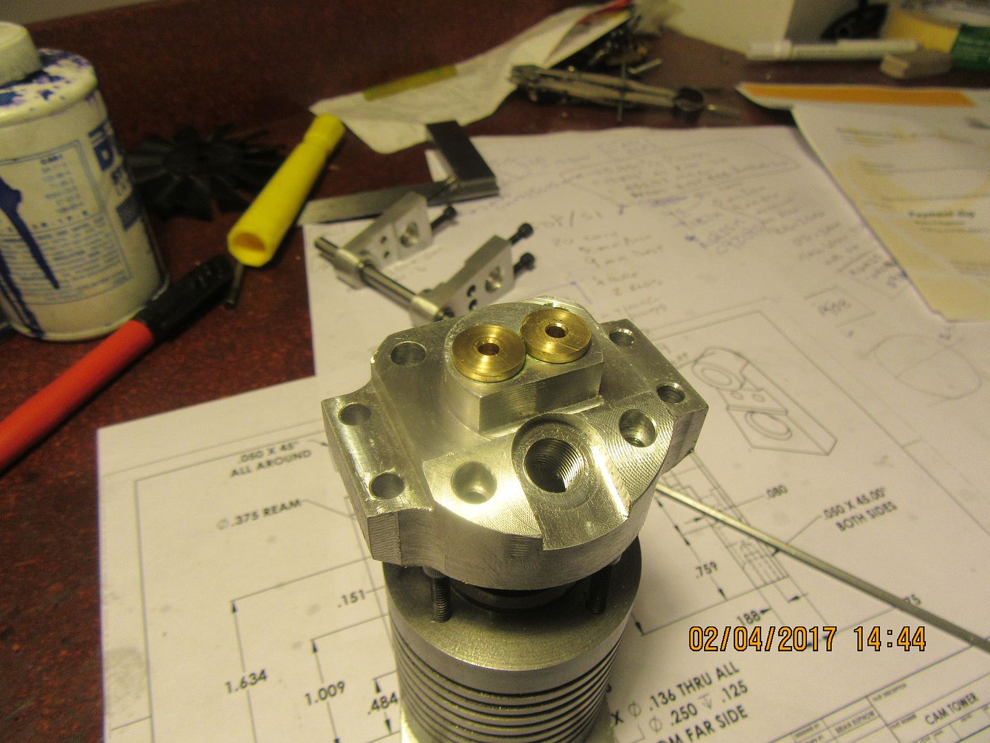
We have valve cages, all finished and installed except for the seat area which will get done later, and the hole thru the side from intake and exhaust, which will be drilled thru both the cylinder head and the valve cage after the 620 Loctite they are coated with sets up for 24 hours. One was a fairly easy press into place with my two ton arbor press. The other was a harder press, and made it all the way home except for the last .035", which simply wasn't going to go in any farther. This was cause to get out my 5 pound hammer, a piece of brass to use for a drift, and a step over to my anvil. Two good whacks, and it went all the way home. Maybe if I machine things for another 20 years I'll get this press fit business sorted out.
 
I guess the question now is "What do I do next." I realized when I designed this engine and valve train that there is no allowance in the design for adjusting the valve lash. That's okay on a "one of" engine, it just takes a bit more time. The secret to adjustment is all in the yellow "lifters". They must be made to a very precise length.---Actually it is a case of making them a length to suit everything else. So, I make the cams and install them on the shaft. I make the valves, lap them, and install them in the cylinder head. Then, making certain that the valves are seated properly in their cages, I measure the distance from the end of the valve stem to the "low" side of the cam. This resultant measurement will give the length from the inside bottom of the lifter which bears against the end of the valve stem to the face of the cam. Then I take about 0.006" from that measurement and subtract it from what I measured to give the appropriate amount of valve lash, and make the lifter to that exact length. This is more work than just turning a screw to set the valve lash, but it allows me to use relatively short "towers" above the cylinder head.
 
After what seemed like a lot of time today I have managed to make cam #1. It is made from 01 drill rod, and after the set screw holes are tapped into the hub, it will be flame hardened. I made it the way I had outlined in my thread "An easy way to make a cam" but this time I ran the mill in it's conventional direction instead of reverse. Of course this meant that I had to spend an unconscionably long time finding a boring bar that would fit in my boring head, and grind up a cutter from HSS to work for this application. Since this method has the cutter turned to cut from the outside in, none of my brazed carbide tools would work. I spent longer trying to get a cutter and holder sorted out than it took to cut the cam. The cam isn't 100% because of cutter deflection, etcetera, but it's damned close. I will use it and if it works, great. If it doesn't work properly, I will make another.---Life was a lot simpler before people told me that cutting a cam with the mill running in reverse might unscrew the shank of my boring head!!
 

Latest posts

Back
Top