Potty Popcorn Engine

Home Model Engine Machinist Forum

Help Support Home Model Engine Machinist Forum:

This site may earn a commission from merchant affiliate links, including eBay, Amazon, and others.
Thanks for your positive support chaps

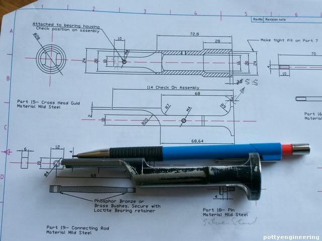
Stew---Thank you for the drawings. They are very well done. Did you have formal training as a draftsman at some point in your career? It has been my experience that most good machinists don't make mechanical drawings, and most mechanical draftsmen don't machine.--And, out of curiosity---How is the crosshead guide attached to the cylinder cap?----Brian

Brain:- I had what I suppose you would call a technical education, I did some tech drawing at what we called secondry school (up to age 15) then I did a 5 year apprenticeship and took city and guilds and a Higher National Cert in engineering at day release and night school, that had an element of drawing practice, a few years ago I went back to night school and did a basic autocad course just out of interest, never got as far as the 3D cad,
Before that I did a degree in science and technology with the Open University (home study), I chose units that had a high level of engineering design and technology, by far my favourate unit was on the history of the Industrial Revolution in the UK, it went into why it came about. I also earned a living as a project engineer in a design department, my wife recons that I never really retired, that I just carried on my work as a hobby :-\

Between you and me, I've got a bit of a blind spot when it comes to 1st and 2nd projection I get them mixed up.

The cross head is just a tight fit on the steam chest cover (cylinder cap) at the front end it fastens to the crank shaft bearing support, trapped between these two parts it can't go any ware, you can see this set up on the full size engine but with them, the end turns through 90 deg to bolt onto the bearing support, this would have bin difficult to reporoduce in bar stock.

Thaks for you interest guys.

Stew

 
I've got no pics of this mornings work, I just finishing off the piston and tidied a few things up. I took delivery of a length of 3/8" hex yesterday so I made the gland nuts, for you guys who I've sent drawings to I changed these some what, I decided that as drawn they looked out of proportion, so shortenend the length of thread by 2mm and the thickness of the head by 2mm.

I've realy bin pleasantly suprized by how many have asked for the drawings and the reaction to them, thanks a bundle Guys. My reason for sending them out and not posting them for download was:- I new I would make changes, and I wanted to stay in touch with the people who had them so I could send them the updated drawing pack, I also thought it would be a good way to get them proof read.

I intend to draw up a valve, displacement lubricator, and governor for it, but I won't do that until I've got the engine completed, so that I can get an idea of proportions and how things will fit together.

Thanks again for you support

Stew


thanks stew for the change update, getting stuff ready to start flywheel. looks like you are making good headway. i changed the number to english as all my tools are that. thanks again,yours is looging good jonesie
 
Stew---you definitly get Karma for being brave enough to post your drawings and for doing such amazing work. All the rest of you chaps who are following Stews work or downloading or being sent his drawings---give Stew a Karma by clicking his applaud button. If you had to pay out of pocket for his designs, You would be paying from $20 to $50.00. Stew can't spend his Karma, but it will give him a sense of how much we appreciate what he is doing.----Brian
 
Hey Stew,
As you requested, I've given the drawings a once over....OK maybe a two or three times over... ;D

What I found was small....but I did find some stuff.

Page 1 ....GA clean

Page 2.....zone D7 The bore dimension of the hub is missing ..I assume it's 4mm.

page 3....clean

page 4....clean

page 5.....zone C4 A dimension is required from the centerline to one side of the 10mm wide centerline web
Zone B6-B7 A thread callout for the ends of the pistion rod....I assume M4.
zone D4 Missing diameter call out for the bearing diameter of the pin I assume it's 5mm?

page 6.... zone C3 Part 21, The dimension is missing on the pad that forms the mount for the crosshead guide. I assume its
2mm deep or 6 mm from the backside....
zone A7 The crank pin diameter is missing...I assume it's 4mm?

Lastly....a request from me. On page 4 add a pair of M2 screws to hold the steam chest in place while the valve is being set.
When I built Rudy's "Little Work Horse"....which was an identical chest design, it was a pain to get the chest to line up again once you were ready to put the cover back one. I added a couple of screws on the chest only to hold it in place while the cover was off. The steam chest cover , covers those screws once assembled.....however this is a very minor point.

I like the design alot! To me is screams for a small generator to sit between the bearing journals! Can't wait for the governer!..... ;D

And some Karma from me too!

Dave


Lastly....a request from me. On page 4 add a pair of M2 screws to hold the steam chest in place while the valve is being set.
When I built Rudy's "Little Work Horse"....which was an identical chest design, it was a pain to get the chest to line up again once you were ready to put the cover back one. I added a couple of screws on the chest only to hold it in place while the cover was off. The steam chest cover , covers those screws once assembled.....however this is a very minor point.

Which is why I almost alluz fit the steam chest with studs!

Karma from me as well Stew!
 
I feel a bit foolish for asking----But why is it a "Popcorn" engine. I know about old time pop corn vendors having a steam driven engine on their "Popcorn wagons" to turn the drum of popping corn, but you write in your drawing that this is a 1/3 scale model. Was the original "Popcorn engine" really 3 times bigger than what you have designed?
 
Hey Brian,

YUP about 1/3 size of a Cretors

http://www.myersengines.com/engines/popcorn_engine.htm

Cretors used mild steel on the governer valve spool which results in the valve sticking shut after some period of non use and results in the 17 something year old operators looking dumb founded as to why it won't work even when the safety is popping off resulting in the Chief to tell his Volunteer Engineer to take it off! "Damn thing!" Works well if you use it every day....but don't let it sit!

Make the governer parts out of bronze or stainless please............ ;D

Dave
 
Thanks for the Kalma's Guys

Thanks for the proof read Dave I've penceled the changes in on my working drawings I'll catch up with the cad changes later.

I do the same as Tel and fit studs, but I had noticed on pictures of the engines that they nearly always use slotted screws, so figgure I could just use a couple of shortend bolts to hold things down while I set the timimg.

Thanks for the info on the governor:- Bronze and stainless it is then.

I guess some of you Guys are wondering how a Limey knows about popcorn engines, well you can blame Bogs for that one, he showed me some drawings he had for a wobbler type popcorn engine, that got me thinking, did a little reasearch and found pictures of the Creaters and Dunbar slide valve engines, they looked interesting and their aplication is unusual for the UK, and I like the unusual.

Stew
 
Made a start on the cross head guide bar, I'm using a bit of 32mm dia free cutting mild steel, but aluminium could be used if you wish.

This is the type of job you have to think through to get the correct machining sequence, the important features are the 16mm bore that the cross head works in and its concentricity to the 24mm counter bore that the front cylinder cover fits on, this will keep the cross head centre line on the same centre line as the cylinder bore.

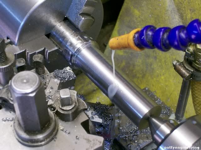
First op centre drill and turn down the 24mm diameter,

131_0638.jpg


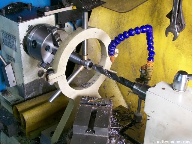
As the wall thickness at this end will only be 2mm I wanted to drill the 20mm as the last op, so I put down a 3/8" pilot drill followed by 1/2" roughing drill. For these drilling operation I had to support the front of the bar with a fixed steady.

131_0641.jpg


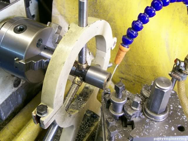
Flip the bar round, and face to length and turn 28mm dia.

131_0642.jpg


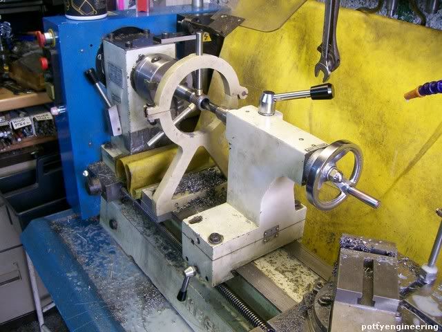
I was strugling to get enough reach on the tail stop over the top of the saddle, so I though if a take the sadle off I'll get closer, then I though, no if I take the tail stop of and put it in front of the sadle that would be a lot easyer.

131_0644.jpg


Drilled with a searise of drill finished drilled the 20mm dia, then put a 15.5 mm drill through, and finshed of the cross head dia with a 5/8" reamer, I was real lucky that I hade thease sizes amongs my limited selection of larger drills and reamers. I was planning on boring this dia out but I hadn't got a boring bar that long, and if I had it would be a dificult job, being on the long side to get a good result, if you havn't got a reamer a drill with corner slightly radiused would do the job, the size is not that critical you can make the cross head to fit.

Bored the 24mm counterbore a nice push fit on the front cover.

131_0648.jpg


As these two critical feature were finished at the same setting they should be nice and concentric.

Swap it round the other way and finish the other end off with a 20mm drill to depth.

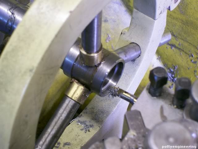
Her it is on the cylinder.

131_0654.jpg


Tomorrow I'll mill it to its final shape.

Stew


will add the changes to my prints. a karma from me also jonesie
 
Stew:
thanks for the plans. Have not had a chance to open and print yet. MRS Tin and I share the computer with the e mail on and work has been crazy feels like we need a month to finish out the last week of the month.
Tin
 
Nice progress, Stew. I'm very interested in seeing how the crosshead guide turns out. I've always admired the style of crosshead guide used on the Cretors popcorn engine but never took the time to figure out how to machine a replica. Give us some nice pictures... ;)

Chuck
 
Thanks for your interest Chuck

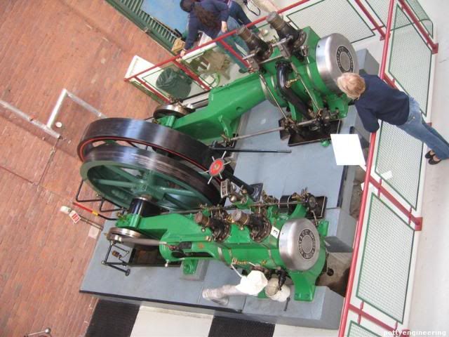
For some reason I had it in my head that this type of cross head guide was vee shaped couldn't work out how they made them figgured that they used a big slotter. Then last month we visited the Northern Mill Engine Society running day in Bolton http://www.nmes.org/ they have a number of horizontal their that you can get up close and have a good study, it was then that I relaised that they were round, this opened up the posibility for making one.

Her's a pic of a cross compound, with corless valve, I was mesmerised by their action just like the guy lady in the shot.

IMG_3377.jpg


I keep pondering on how to model a corless valve set up.

Stew

Stew
 
I'm very interested in seeing how the crosshead guide turns out. I've always admired the style of crosshead guide used on the Cretors popcorn engine but never took the time to figure out how to machine a replica. Give us some nice pictures...


Ok Chuck plenty of pics it is then.

Before milling the guide out I had a little corrective work to do, when I did the lose assembly I found that the nuts on the cylinder cover stopped the guide sitting down, so I set it back up in the lathe and cut the 24mm dia 2mm deeper.

To Mill out

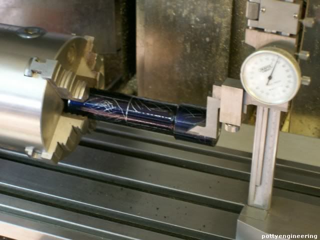
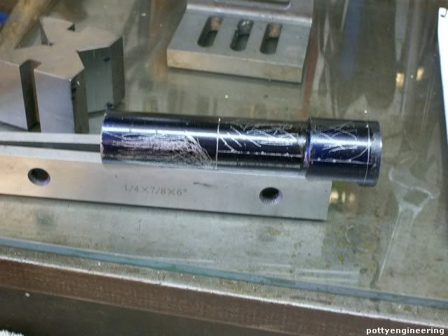
First up I blued the guide up and using the spin-idexer marked it out, and cross hatched the bits to cut away.

Milling it out doesn't call for exact presision, you're trying to get a neat visual effect, the origonals were cast so they would have had inperfections.

131_0656.jpg


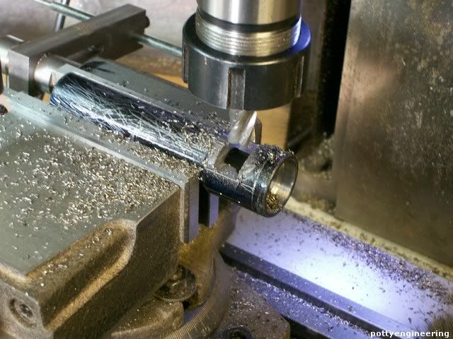
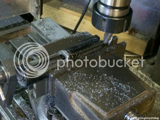
On the mill first mill across the end keeping it short of the corner, this is so I would have room to run the cutter and take advatage of the horizontal power feed,.

131_0660.jpg


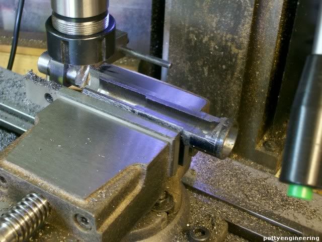
Then mill down to the line.

131_0663.jpg


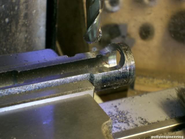
Using a 14mm dia ball nosed cutter clean out the corner.

131_0665.jpg


Now I had a nice flat platform to sit on to do the other side.

131_0667.jpg


I swung the vice round 90 deg again so I could take advatage of the power feed, and milled out 68mm gap. For some time I was trying to figure out the best way to grip the job to machine the 10mm wide support, that bolts to the bearing stand, whilst doing this op I realised that the solution was stearing me in the face, all I had to do was mill into the the edge until it cut through into the bore.

131_0672.jpg


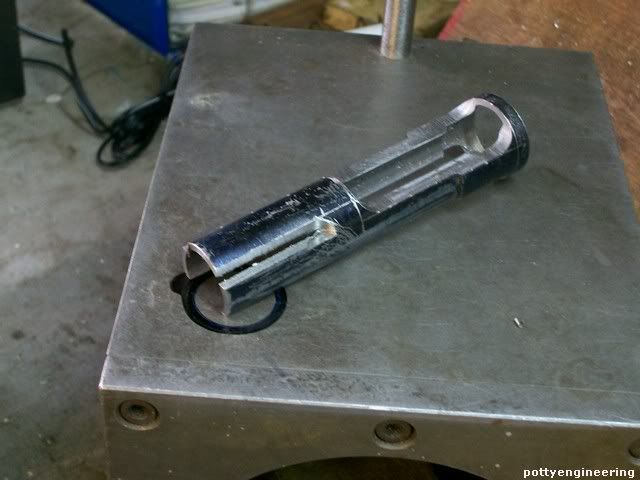
So that you have this.

131_0675.jpg


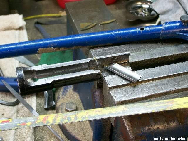
It is now a simple matter to use an hack saw to finish the job off.

131_0676.jpg


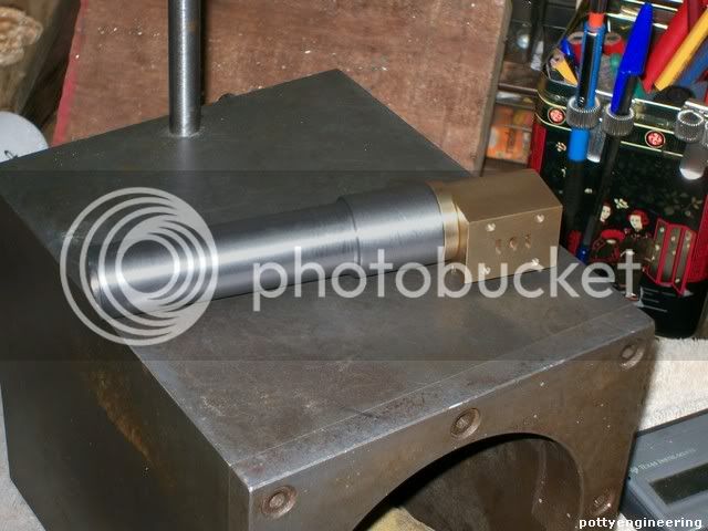
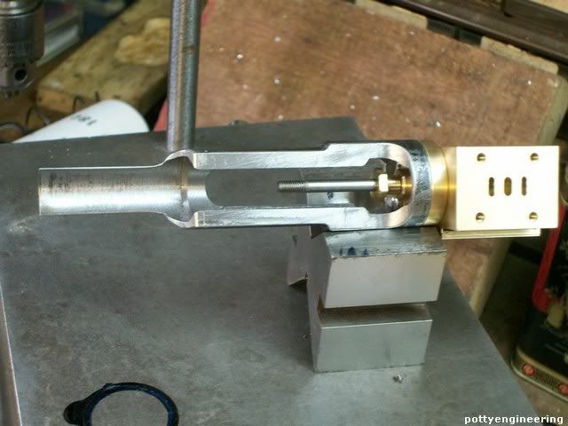
1/2 hr work with files to blend every thing in and you have this.

131_0678.jpg


131_0682.jpg


Its not quite finished yet I'm unshure how the crank will clear the end of the Guid I may have to but a dog leg bend in it, I'm going to leave this untill I've got more bits arround me.

I didn't quite get the depth of some of the drilled holes correct I was short from both ends with both the 20mm holes don't know what I did wrong probably a maths error. but it won't be any detriment in fact it will just mean the cross head will be supported over a longer distance.

Stew


Just caught up with this one Stew, after a fortnight away in sunny Devon, and I have to say it I like what I see. It’s up to your usual high standard and if it runs anything like that beautiful Overcrank you built (which I am still dreaming about building) we will all be well pleased.

Do you have a link to the flywheel thread you referred to, I am fascinated to see how you achieved that spoke detail. Keep up the good work. Oh yes, and Karma from me too

Les
 

Latest posts

Back
Top