Cedge
Well-Known Member
- Joined
- Jul 12, 2007
- Messages
- 1,727
- Reaction score
- 28
Guys...
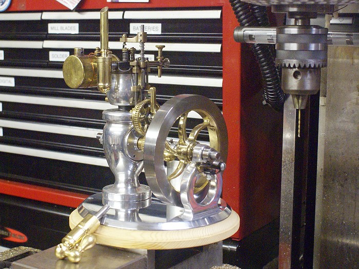
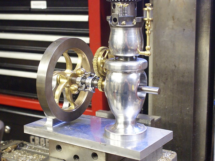
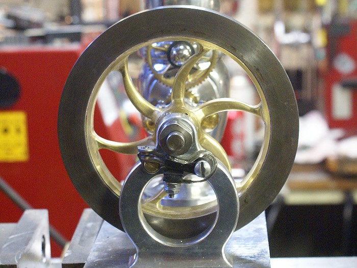
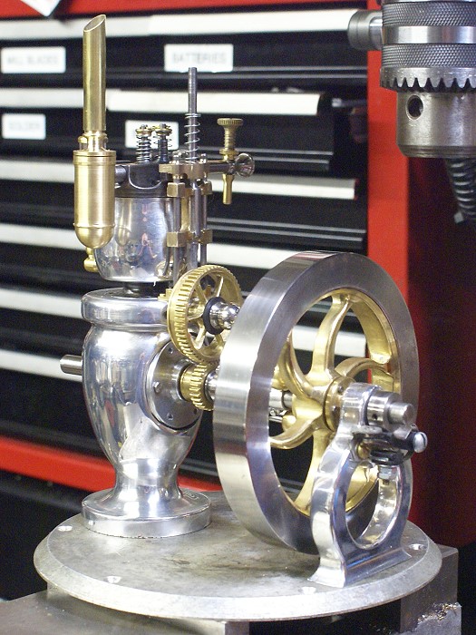
I really appreciate the encouragement and the kind words. The last post ended with a couple of teases, like the flywheel blank and tank test placement. The flywheel has come a ways since then. I modified the 5 spoke instructions given in one of the Duclos articles to make it a 6 spoke version. This took a little rejiggering of hole sizes and placements, as well as the radii of the spoke curves, but nothing brain stretching about it.
The project kept getting delayed by family matters, including an 8 hour middle of the night round trip drive to retrieve my son and his broken arm from a wilderness camp in the Great Smokey Mountains. Nicholas is doing fine and seems to ignore the pain as if it were nothing. I finally got back on course late yesterday and made up for some lost time.
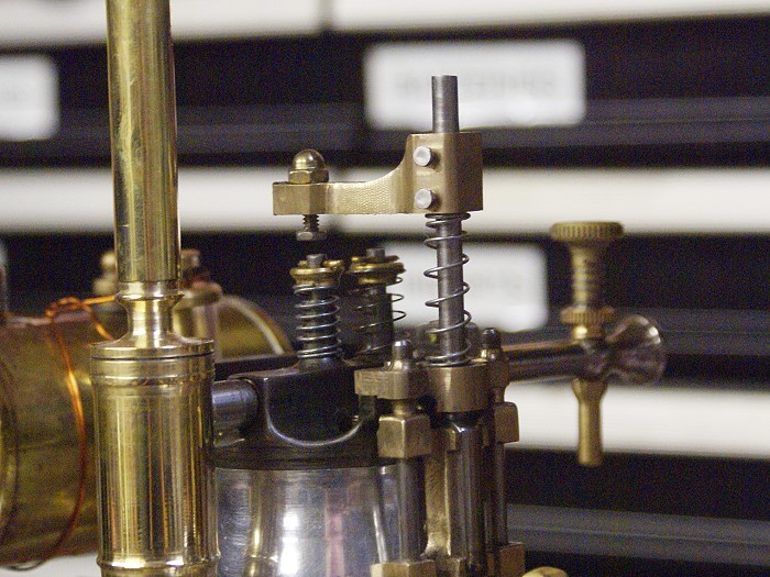
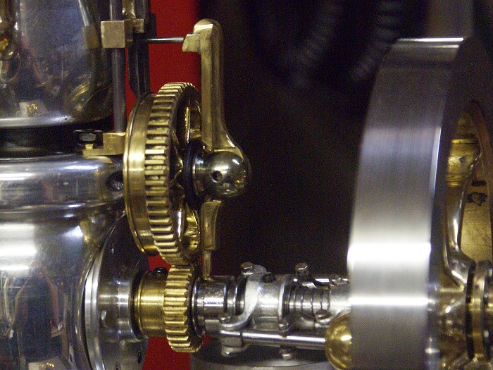
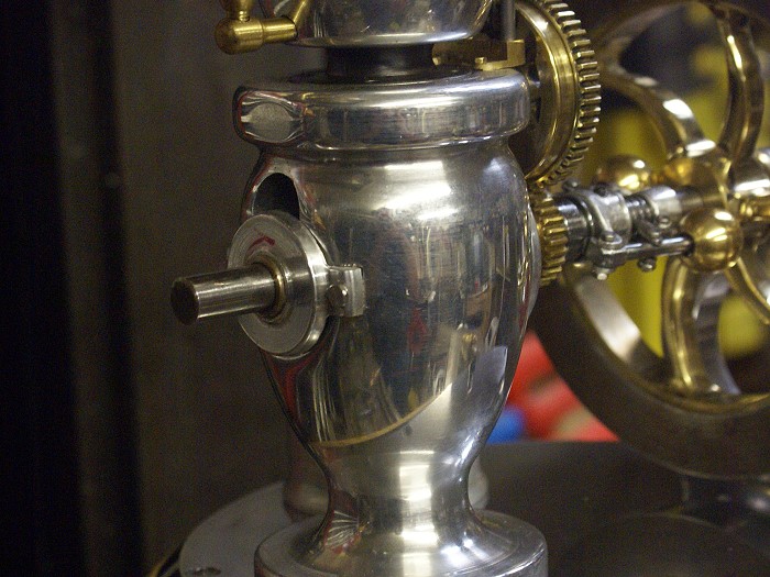
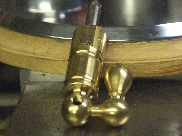
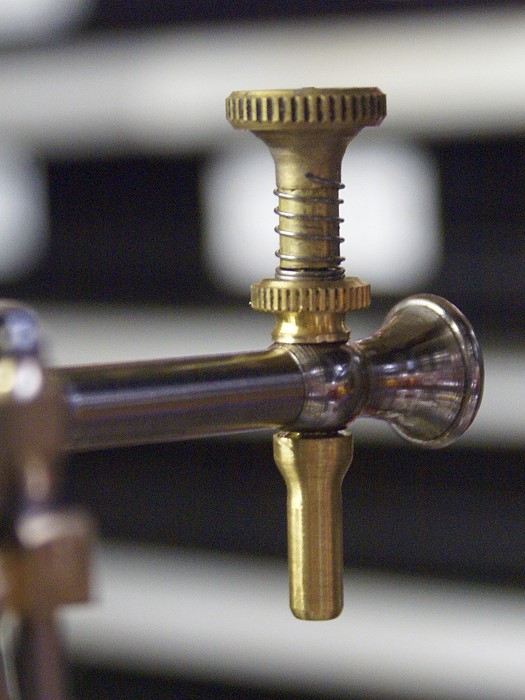
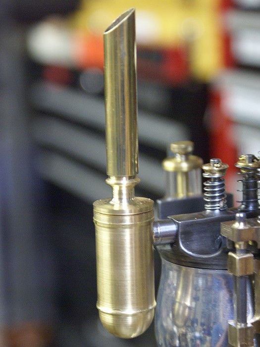
The photos below show the flywheel just after it was mounted for testing the wedge lock which secures it to the shaft. This is basically a cone that has been split at 90° so the 2-56 screws can force it to squeeze the crank shaft. Quite an effective way to mount a flywheel. All the hand filing work is now done, but the flywheel will see quite a bit of hand polishing yet, before the job is done.

I think I'm on the right track with the engine, but will be visiting a local model IC engine guy tomorrow, just to let him critique the project so far. Not having messed with IC engines, I'd like to be sure I'm on track for a runner.
For those who are curious about making curved spoked flywheels, I posted a write up back in October on the subject. You can check it out at http://www.homemodelenginemachinist.com/index.php?topic=3169.0
Steve
I really appreciate the encouragement and the kind words. The last post ended with a couple of teases, like the flywheel blank and tank test placement. The flywheel has come a ways since then. I modified the 5 spoke instructions given in one of the Duclos articles to make it a 6 spoke version. This took a little rejiggering of hole sizes and placements, as well as the radii of the spoke curves, but nothing brain stretching about it.
The project kept getting delayed by family matters, including an 8 hour middle of the night round trip drive to retrieve my son and his broken arm from a wilderness camp in the Great Smokey Mountains. Nicholas is doing fine and seems to ignore the pain as if it were nothing. I finally got back on course late yesterday and made up for some lost time.
The photos below show the flywheel just after it was mounted for testing the wedge lock which secures it to the shaft. This is basically a cone that has been split at 90° so the 2-56 screws can force it to squeeze the crank shaft. Quite an effective way to mount a flywheel. All the hand filing work is now done, but the flywheel will see quite a bit of hand polishing yet, before the job is done.
I think I'm on the right track with the engine, but will be visiting a local model IC engine guy tomorrow, just to let him critique the project so far. Not having messed with IC engines, I'd like to be sure I'm on track for a runner.
For those who are curious about making curved spoked flywheels, I posted a write up back in October on the subject. You can check it out at http://www.homemodelenginemachinist.com/index.php?topic=3169.0
Steve


![DreamPlan Home Design and Landscaping Software Free for Windows [PC Download]](https://m.media-amazon.com/images/I/51kvZH2dVLL._SL500_.jpg)


")