Open Column Launch Engine from Kit

Home Model Engine Machinist Forum

Help Support Home Model Engine Machinist Forum:

This site may earn a commission from merchant affiliate links, including eBay, Amazon, and others.
Carl,

I looked at LMS's Rotatry Tables and the 4 and 6 inch RTs are listed as having a MT2 taper. The "A" dia. for a MT2 female is .700. "A" being the large end dia. I used my DTI to sweep a 1.000 id for a sleeve bearing. (See attached photos.) This was done by setting stem on the dovetail at the base of the DTI and adjusting the angle of the Contact (stylus, tip, etc). How big is the hole in your RT or am I really missing something? I would think this should work if you are just looking to center the Spindle to the RT.

Note: On an AGD style DTI you can change the contact point angle in relationship to the indicator centerline. (See last two attached photos.) It's basically a friction clutch. The contact can be pushed beyond the end of the range of travel of the DTI. Just put it where you want it.

A 1.000 dia. would probably be the max dia. that could be done this way for obvious reasons. In this setup, the closer the contact angle comes to 90 degrees, the working plane changes from that of vertical to horizontal.

Bob

DSC02391.JPG


DSC02392.JPG


DSC02393.JPG


DSC02394.JPG
 
Answering some questions...

Foozer,

Yeah, like that. Maybe the push rod you show isn't needed if the rods are in a 1-2-1 configuration and the screw bears on the top '1'. Needs must try it and see.

Interesting math problem there. How does one compute the equivalent of the outer Soddy circle for four equal tangent hexagons?


Carl,

When you mount a 3jaw to a RT (not my cup of tea), the chuck axis has to be aligned to the RT axis and both must be aligned to the mill axis.

If you mount the RT and get it aligned, then, when you mount the chuck to the RT, you can use the RT to spin the chuck against a DTI mounted in the mill collet.

Try it both ways and you'll see what I mean.

Filing on the lathe...

The danger is that you'll file too close to the spinning chuck jaws, a jaw catches the tip of the file and propels it back toward you (lathe turning CCW). If that happens, an unhandled file tang can be driven into your hand or body. Also, your left hand/arm is dangerously close to the spinning chuck jaws. One absent-minded jerk (of the body) due to a sonic boom, earthquake, doorbell, whatever and you can get way too familiar with your machinery or end up as a Nicholson shish-ka-bob.

If you're right-handed:

lathe CCW - handle in LH, tip in RH
lathe CW - handle in RH, tip in LH

It would be nice if somebody would make a file that cuts on the pull stroke for the latter case above.

With a collet chuck, there are no chuck jaws. In addition to improved safety, collets:

are more accurate
grip without marring
grip better
can hold parts that can't be conveniently held in a 3jaw
can be used to advantage in the mill vise with collet blocks.

Well, I wouldn't exactly call what we're doing instruction since it's mostly reactive (you do something - we tell you it's wrong :) rather than actually telling you what to do a priori) but your point is still well taken. There's a whole lot of folks out there who have the "hold my beer and watch this" approach to every problem and you don't want to be getting your guidance from them. Evaluating the teacher is an important part of all education.

Attaching emery strips to a wooden batten, as was suggested earlier, is a good idea but I find it hard to follow small, intricate contours that way so I usually hand hold the strip. However, I do always hold it in such a way that I can't hang on to it if the machine decides to grab it.

Emery works better for finishing if you put a drop or two of oil on it.

Scotchbrite works well too although it produces a slightly more matte finish (that polishes nicely with a stiched buff). Note that many different grades of Scotchbrite are available. The finest (usually white in color) does really nice work.

Rockler used to sell a package containing a graduated series of abrasive mounted on small foam pads for the woodworking guys. They do a fine job of blinging if one is into that - I'm not, I like the industrial look.

Looks like they still sell them...

http://www.rockler.com/product.cfm?page=11435

Their sanding cords are handy too...

http://www.rockler.com/product.cfm?page=9926

Spend some time in the local Rockler store if there's one close. They have a number of things that guys like us can use. Sign up with them and they'll send you lots of discount coupons. All my diamond sharpening blocks/stones were bought with discount coupons.

 
90LX_Notch said:
Note: On an AGD style DTI you can change the contact point angle in relationship to the indicator centerline. (See last two attached photos.) It's basically a friction clutch. The contact can be pushed beyond the end of the range of travel of the DTI. Just put it where you want it.

That's it! Thanks Bob. It seemed fragile and I didn't want to mess with it much. I think I can do this now. Thanks!

AGD? American Gage Design Specification?
DTI. Dial Test Indicator.

 
mklotz said:
It would be nice if somebody would make a file that cuts on the pull stroke for the latter case above.

If my assumption is right...this was a nice way of saying..."Zee, the file cuts in one direction...and it's not the direction you're holding the file in." To expose my ignorance further (remember...I just deal with 1's and 0's and the occasional electron), do files cut in one direction, both, better in one than the other?

mklotz said:
Well, I wouldn't exactly call what we're doing instruction since it's mostly reactive (you do something - we tell you it's wrong :) rather than actually telling you what to do a priori)

Before the fact...after the fact...I'll take good instruction any way I can.

mklotz said:
Emery works better for finishing if you put a drop or two of oil on it.

Maybe someone will add to the 'True Grit' post and explain why. (Cause I don't know.)


mklotz said:
Scotchbrite works well too although it produces a slightly more matte finish (that polishes nicely with a stiched buff). Note that many different grades of Scotchbrite are available. The finest (usually white in color) does really nice work.

I had no idea there was anything other than green! Are there other colors besides white and green?

The last several posts by everyone have been awesome. It's going to be real interesting to go through this thread and collect learnings.
 
My mistake. The instructions do call for additional measuring once the chuck is in place. But I think it's because they're using a custom holder to mount the 3-jaw chuck onto the rotary table (RT). There's also a couple of custom spacers. Remember my rant? Sigh.

I think I'm in luck though. I have a mounting kit! Aha!

But things get real complicated now. It doesn't help that the text's references to the figures don't match. Or that at the bottom of page 28...there's this...

"There's no need for"

For what? What don't I need? There's a page 29...but it has a new paragraph. Argh!

Instructions call for a dowel pin in the spindle, lower the spindle until the pin is in the chuck, then tighten the chuck. Spin chuck until you get a certain orientation then lock the chuck down. Remove pin from spindle and replace with DTI. Put pin back in the chuck as shown in figure 87 (which is figure 95). That sounds pretty strange to me. The idea then is to loosen the chuck and while using the DTI against the pin, bump the chuck to get it into position. Okay...that part makes sense...if I hadn't mounted the chuck on the 'purchased' mounting plate. I doubt the chuck will move at all. Maybe I could get a couple thou if I remove the nuts holding the chuck to the plate and use clamps instead.

Luckily, this thread is more about learning than getting an engine to run. (Don't no one say it. I will. If I don't get the engine to run...what did I learn?)

This is a little too much like the video that came with the Model #2A kit I bought. Towards the end of the project, the author did a "let's hurry up and get this done".

Sorry...I don't mean to keep going at this manual...it just really steams me to think how this can easily produce an unsatisfactory result for the beginner and so raises the chance that they'll just give up.

(Not me though! I'm already prepared to ruin this rotary valve and have another go. I may blubber for a while...but it's good for you. I mean me.)

The next part calls for putting the pin back in the spindle and moving it to some location. They are kind enough to specify the y distance. But they don't mention the x distance...and I believe that is going to depend on the diameter of the slitting saw.

Oh but first, put a longish screw (they don't say how long) in the detail to act as a reference.

Drat. I have to go find a screw. At least it's not custom. [EDIT: Wait. Wait. I can make one! Sheesh Zee. Wait. Wait. I already have one! The columns!] [EDIT number 2: The columns are a #6. The hole is a #8. *****. I'm going to bed.]

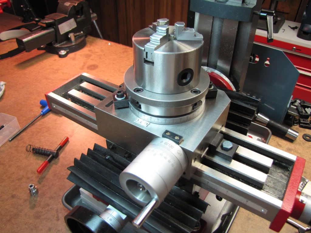
Here's a pic of what I have so far. Woopee. Just a 3-jaw chuck on an RT on a mill.

IMG_0229.jpg


Do you see those clamps on top of the RT that clamp the turntable? You may need to remove them. The T-nuts used to clamp the chuck down interfere as you turn the table.

 
Carl,
"Do you see those clamps on top of the RT that clamp the turntable? You may need to remove them. The T-nuts used to clamp the chuck down interfere as you turn the table."
Now you make special T-nuts to hold the chuck to the R-table with the bolt hole enough offcenter to clear. Its so much fun to make tools to make tools to make tools...
Dave
 
Carl,

Correct on AGD- American Gage Design. I know it applies to Dial Indicators and now that I am thinking about it I forget if it applies to Dial Test Indicators. That may be an international standard. I forget, it's been awhile

Congrats on getting the RT mounted. Unless things are way off isn't there enough play in the plate, tee nuts and Allen screws to get the chuck concentric to the RT? One idea would be to open up the holes in the plate or slot it. The more experienced people can way in on that idea.

As far as the protruding tee nuts: I'd shorten them or make offset ones as Dave said.

There's always the make a fixture route. ;)

Bob
 
Zee,
What worked well for me for centering has been a co-axial indicator.
http://www.use-enco.com/CGI/INPDFF?PMPAGE=384&PARTPG=INLMK3&PMITEM=327-0059

It is the one on the bottom. I also use it for centering the tailstock in the lathe. You can usually pick one up from a vendor like CDCO or Shars for alot less and they help quite a bit. I am saving up for a good test indicator so this was an interim solution that has worked out quite well.

I have the same rotary table. You need to be careful when you turn the table. If you take a big cut and turn counterclockwise (looking down at the table from the front) you are climb milling and if you haven't set your backlash on the tight sided it can dig into your work. Make sure you only go counterclockwise after the cut is done to smooth up the sides.

Good luck,
Sean
 
For any that may be looking for a coax indicator...the SPI version is currently on sale at MSC for $119 (normally $186).

http://metalworking.mscdirect.com/CGI/NNPDFF?PMCTLG=37&PMPAGE=1

The above link is for the Mid-June sales flyer. See page 24. I picked one up a few weeks back and was pleased with the quality.

Regards,
Bill
 
DavesWimshurst said:
Its so much fun to make tools to make tools to make tools...

We now return to the rant. :) Thanks Dave.

90LX_Notch said:
I forget if it applies to Dial Test Indicators.

Unless things are way off isn't there enough play in the plate, tee nuts and Allen screws to get the chuck concentric to the RT?

DTI too. When I googled AGD...the wiki specifically mentioned DTI. That's why I included it in my reply.

I haven't measured yet to see if the chuck is concentric (enough) or not.

Thanks Bob.

Seanol said:
I have the same rotary table. You need to be careful when you turn the table. If you take a big cut and turn counterclockwise (looking down at the table from the front) you are climb milling and if you haven't set your backlash on the tight sided it can dig into your work. Make sure you only go counterclockwise after the cut is done to smooth up the sides.

Thanks very much for the tip Sean. It would not have occurred to me.

Sean and Bill: Thanks for the links on the coax indicator.

Dave and Bob: As for the clamps...why not just remove them? I can't use them anyway since I'll be turning the table during the cut. By the way, not all of the nuts interfered. One thing I had not checked is to see if they would clear by rotating them. (i.e. the hole for the stud may not be centered - it barely interfered).
 
Just saw your post kvom. My columns already had one end threaded. Would that have made a difference to your approach? Did you mark the columns with the height gauge? (How?)

I didn't mark the columns. After determining the length and computing how much to remove, I chucked the column on the lathe and touched the lathe tool off to the face. Then I moved the carriage the appropriate amount. I have a DRO on the lathe, which makes this easy. However, a dial indicator attached to the bed with a magnet works just as well.
 
Answering some questions, etc.

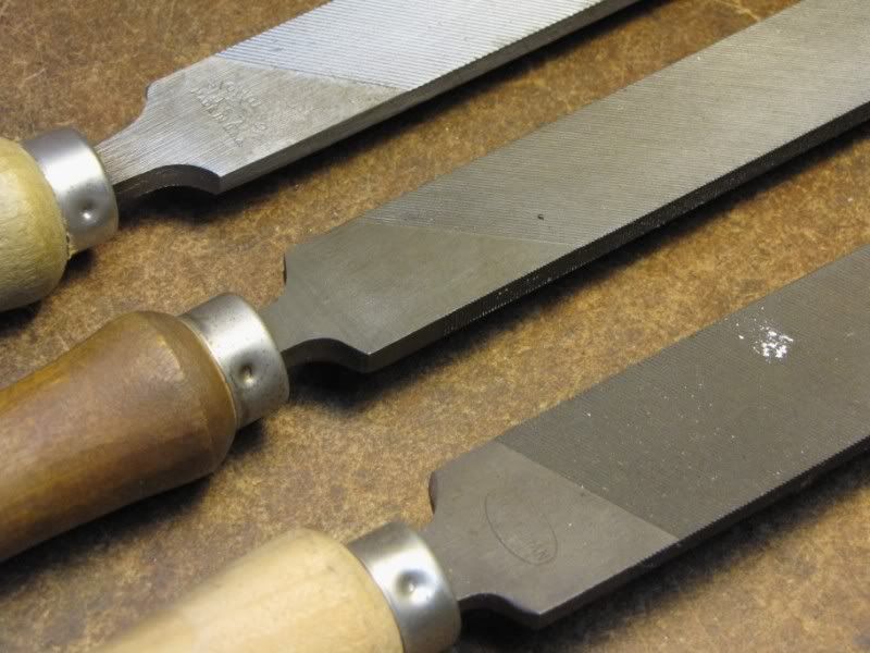
Files are not abrading tools like sandpaper. They have distinct teeth so they're cutting tools. On all the files I've seen those teeth point away from the handle end of the file so the file cuts when you push it forward,

When using a file you lift it off the work on the return stroke - don't just drag it back. Dragging it back dulls the teeth prematurely.

Keep the file clean. I don't care for file cards but many do. Use a piece of scrap copper or brass to push parallel to the teeth. The soft metal will quickly wear to have "teeth" that are a perfect match to the file teeth pitch and will efficiently push the swarf out of the gullets between the file teeth.

Chalking the file before use (especially on soft metals) will help to avoid "pinning". Pins are the tiny bits of swarf that stick persistently in the gullets and prevent the teeth from cutting as intended. They can also mark the work and prevent you from getting a smooth finish.

There are special lathe files made for... wait for it... use on the lathe. They're single cut and have a steeper angle of the teeth relative to the file axis. This provides more of a shearing action. Buy them if you see them offered cheaply at a swap meet - they're good tools - but don't sweat it, ordinary files used judiciously are perfectly acceptable.

Scotchbrite comes in (at least) maroon, green, grey, white (I *think* that's in order of coarsest to finest). There may be others but those are the ones with which I'm familiar.

I would have thrown that instruction book away a long time ago. I have an extremely short fuse for folks who can't take the time to write clearly and proofread what they write before foisting it upon the world. It's not my job to unravel what someone else thinks they've written.

With all due respect to the folks who mentioned it, I really don't think you need, want or even can use a coax indicator. They require enormous amounts of headroom in the mill - probably more than you have available. The good ones are expensive as well and the Chinese clones don't work all that well. (I speak from experience - I was given one and I used a couple of times before returning it to its box and using the box to prop a shelf.)

Furthermore, as a novice, you need to develop your skills using a DTI and an edgefinder. These are the fundamental tools and, unlike the special purpose coax, are devices you'll be using throughout your career in this hobby. Yes, you may need to make some holders and jigs, etc.. but that's another thing you need to adjust to. The reason that setup is 90% of most jobs is the fact that so many jobs require some widget that must be fabricated to achieve what you intend.

Climb milling on the RT...

Take a felt tip pen and mark arrows on the periphery of the RT (where they're visible when the table is covered by the chuck or work) showing the direction of rotation for NON-climb (i.e., conventional) milling. This will be CW (viewed from above). Now mark an arrow on the control handle to show which way to turn it to make the table move in the CW direction. (This will probably be CW also but I can't speak for every RT ever made.)

Sounds childish but do it anyway. Next time you're deep in some complex RT job you may thank me for the suggestion.

Finally...

MAKE YOURSELF A VISE STOP!! From your photos, it looks like your vise jaws project high enough to use this style...

http://www1.mscdirect.com/CGI/NNSRIT?PMPXNO=1802317&PMT4NO=65912359

A version of this is easily fabricated.

If the jaws have enough projection, you might get away with using a small machinist's parallel clamp...

http://www1.mscdirect.com/CGI/NNSRIT?PMPXNO=1757389&PMT4NO=65913148

For reasons I don't want to take the time to explain, I use stops based on the the design of a woodworker's bench stop - see attached diagram.

This is nothing more than a thin piece of stock with screwed on bits of stock. One end locks on the outside edge of the vise jaw and the other provides the stop. This design eats up a bit of the vise jaw capacity but it has the virtue of being made in a few minutes. The end pieces on mine are nicely machined but there's no reason they couldn't be simple screws. A piece of stock, drill and tap for two SHCS and Bob's your father's brother.

stop.jpg
 
I mostly use a stop very like the link Marv posted-- a little clamp that attaches to one of the vise jaws. I think CDCO was giving a knockoff away free or $1 with orders a while back, but it's a simple project to make one-- square off a block. Mill a slot. Drill 3 holes in it. Saw it in half. Press fit pins in the outer holes of one half and tap the center one. Drill clearance holes in the remaining half.

If you use a screwless-type vice, you'll have to do something else though.

 
shred said:
If you use a screwless-type vice, you'll have to do something else though.

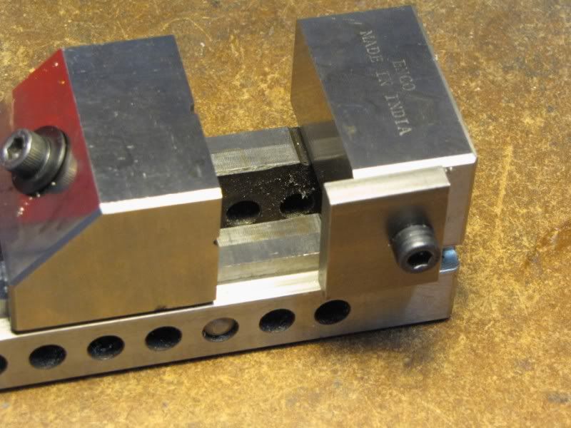
Many of the screwless vises I've seen, including the two I own, come with a tapped hole in the end of the fixed jaw. Requires nothing more than screwing a bit of scrap to the end of the jaw. Since many of these are imports, it's not unusal for the thread to be metric.
 
mklotz said:
Many of the screwless vises I've seen, including the two I own, come with a tapped hole in the end of the fixed jaw. Requires nothing more than screwing a bit of scrap to the end of the jaw. Since many of these are imports, it's not unusal for the thread to be metric.
;D Ah, that's funny. I'm home sick today and thought to myself "well, mine don't!".. but wandered out to the garage to check anyway. Sure enough, there's a tapped hole in the fixed jaw that I'd never stopped to notice before. :bow:

 
kvom: Thanks for explaining. Another good idea I will file away.

mklotz said:
Files are not abrading tools like sandpaper. They have distinct teeth so they're cutting tools. On all the files I've seen those teeth point away from the handle end of the file so the file cuts when you push it forward,

Mm. Another nice way of saying..."Zee, you dolt...you're holding the file backwards."

Just to be clear...I was using the file to put a chamfer on the part. The part was slowly turning in the lathe. Holding the file the way I was was backwards. To properly cut...I would have to hold the file with the handle (the tang) towards me. Which brings me back to...run the lathe in reverse. I don't trust file handles...I want the tang, with or without handle, away from me.

Thanks for all the tips. Very good.

Yes. I would have thrown the instruction book away...but I'm keeping it (good idea or not) so I can document my experience for the poor souls that follow.

mklotz said:
MAKE YOURSELF A VISE STOP!!

OKAY! OKAY! Sheesh. Can anyone guess what my next project is?

Thanks Shred. Guess who's up to help me through my next project?
 
I got to the shop this afternoon and took a few pictures relevant to what I wrote about earlier.

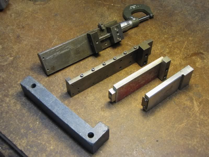
VSTOP1.jpg


Some of my vise stops. The one at the top has an adjustable stop. Along the top edge is a tiny T-slot with an above-the-jaw stop that is also adjustable. Below it is a longer one. On this one, the work stop sits outside the jaws so it can be used with very thin pieces without the need for a pusher block. The next two are non-adjustable stops hogged from whatever scrap was lying about. They're aluminum so, if I mill into them with a small cutter, I'm less likely to break the tool.

The thing on the left is not a stop. It's a solid lead false jaw. Very handy for holding oddly contoured work such as a casting because it will deform slightly to fit itself to the part.

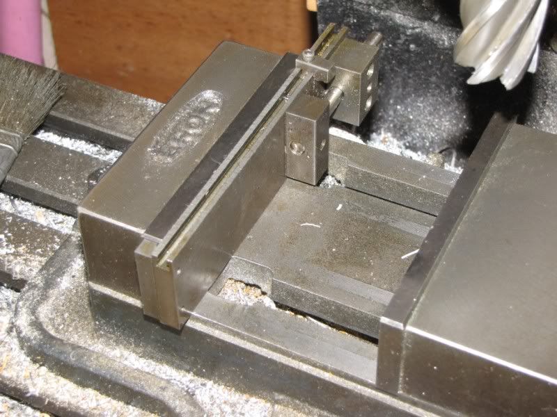
VSTOP2.jpg


Showing how the stop sits in the vise.

Some of you clever minimalists are probably asking, "Why doesn't he just bend a strip of metal into an 'S' shape and use that?" I tried that originally but it doesn't work well. Bending always leaves a rounded fillet on the inside of the bend and, because of that, the stop won't repeatably sit at the same location in the vise. Similarly, the work will not sit repeatably against the stop. The two stops on the left have undercuts on both the part that contacts the jaw and the part that contacts the work so that burrs and small bits of swarf have some place to go. It's important that the stop and the work locate against nice flat surfaces.

VSTOP3.jpg


A tool maker's vise fitted with a stop using the predrilled hole in the fixed jaw.

LFILES.jpg


Two lathe files (left) next to an ordinary file. Note the much sharper angle of the teeth on the lathe file to obtain a more "slicing" cut which leaves a better finish. Also note that all the files have big, dull handles incapable of penetrating human tissue easily.
 
Thanks Marv.

I didn't know about 'lathe' files. Even though I had done some research...and read a book on using a metal lathe (which book showed a picture of holding the file...with tang away).

Lesson: Keep researching...keep reading.
 
it's a simple project to make one-- square off a block. Mill a slot. Drill 3 holes in it. Saw it in half. Press fit pins in the outer holes of one half and tap the center one. Drill clearance holes in the remaining half.

That's a project I made in school last summer, and the first thing I made that I could finish in one session. One modification to the standard model is to make the slot so that the part that clamps onto the face of the fixed jaw is thinner than your normal parallel (e.g., 1/8"). That way you can clamp thinner pieces.
 
THROW THE INSTRUCTION MANUAL AWAY!

1) It's incomplete.
2) More important...IT GIVES UNSAFE INSTRUCTIONS!!! [EDIT: I should say...IT DOES NOT GIVE SAFE INSTRUCTIONS...you'll see what I mean in the next edit below.]

I was not hurt...because I didn't even try this.

Besides the debacle with the 'finger on the cylinder cap' now it wants me to 'touch off the detail's shoulder using paper'. Yeah right. I got a spinning 3" slitting saw with a shoulder barely over 1/8" and a part in the way. There's not enough room.

[EDIT: The instructions did not say to do this with the saw spinning. And, I should've known this since I've already done one operation with the saw and paper (and no spinning). But the instructions are not clear and a beginner might easily think they should have the saw on. You can't count on people's common sense. I don't even count on mine.]

These instructions are NOT FOR THE BEGINNER. At least not without the help of a great forum like this one that will guide you and warn you of the dangers.

&(*^&* :rant:

Not to worry though...the core of me is ;D
 

Latest posts

Back
Top